EP0465440A1 - Carter de protection pour un arbre de transmission et moyens pour sa lubrification - Google Patents
Carter de protection pour un arbre de transmission et moyens pour sa lubrification Download PDFInfo
- Publication number
- EP0465440A1 EP0465440A1 EP91830270A EP91830270A EP0465440A1 EP 0465440 A1 EP0465440 A1 EP 0465440A1 EP 91830270 A EP91830270 A EP 91830270A EP 91830270 A EP91830270 A EP 91830270A EP 0465440 A1 EP0465440 A1 EP 0465440A1
- Authority
- EP
- European Patent Office
- Prior art keywords
- protective casing
- tube
- transmission shaft
- grease nipple
- telescopic
- Prior art date
- Legal status (The legal status is an assumption and is not a legal conclusion. Google has not performed a legal analysis and makes no representation as to the accuracy of the status listed.)
- Granted
Links
- 230000001681 protective effect Effects 0.000 title claims abstract description 47
- 230000005540 biological transmission Effects 0.000 title claims abstract description 25
- 238000005461 lubrication Methods 0.000 title claims description 8
- 239000004519 grease Substances 0.000 claims abstract description 27
- 210000002445 nipple Anatomy 0.000 claims abstract description 21
- 238000007789 sealing Methods 0.000 claims abstract description 14
- 239000000314 lubricant Substances 0.000 claims abstract description 10
- 238000005452 bending Methods 0.000 description 2
- 238000010276 construction Methods 0.000 description 2
- 230000008878 coupling Effects 0.000 description 2
- 238000010168 coupling process Methods 0.000 description 2
- 238000005859 coupling reaction Methods 0.000 description 2
- 230000001050 lubricating effect Effects 0.000 description 2
- 230000001419 dependent effect Effects 0.000 description 1
- 230000000284 resting effect Effects 0.000 description 1
- 238000004513 sizing Methods 0.000 description 1
- 238000003466 welding Methods 0.000 description 1
Images


Classifications
-
- F—MECHANICAL ENGINEERING; LIGHTING; HEATING; WEAPONS; BLASTING
- F16—ENGINEERING ELEMENTS AND UNITS; GENERAL MEASURES FOR PRODUCING AND MAINTAINING EFFECTIVE FUNCTIONING OF MACHINES OR INSTALLATIONS; THERMAL INSULATION IN GENERAL
- F16D—COUPLINGS FOR TRANSMITTING ROTATION; CLUTCHES; BRAKES
- F16D3/00—Yielding couplings, i.e. with means permitting movement between the connected parts during the drive
- F16D3/84—Shrouds, e.g. casings, covers; Sealing means specially adapted therefor
- F16D3/841—Open covers, e.g. guards for agricultural p.t.o. shafts
Definitions
- the present invention refers to a protective casing for a transmission shaft with universal joints of the type that includes a system of telescopic tubes that cover two telescopic tubular elements that connect the first and second universal joints on the aforementioned transmission shaft.
- Protective casings of this type are already known in the art, that in Patent USA-A-4.435.166 for example.
- This protective casing also has two elements or cowlings that cover the joints on the shaft, which are connected by the system of telescopic tubes.
- this type of protective casing, and other similar types cover the entire transmission shaft formed by two universal joints and two tubular elements that form a telescopic connection.
- the tubular elements require lubricating from time to time. This task requires uncoupling the transmission shaft and removing the two tubular elements so that lubricant can be applied. This amounts to a time consuming and difficult task, which is often carried out less frequently than is necessary to lubricate the shaft well thus ensuring it operates correctly and is not subject to excessive wear.
- the object of the present invention is a protective casing of the type described above, that does not have these drawbacks and which, in particular, allows the transmission shaft to be lubricated without complex operations that involve uncoupling the transmission shaft.
- a protective casing of the above mentioned type is characterized in that means for lubricating, from the exterior, the two telescopic tubular elements that connect the two universal joints, are attached to one of the two telescopic tubes of the protective casing.
- a lubricant generally grease
- the means of lubrication are connected to the inner telescopic tube, and include devices that make it possible to lubricate the exact area where the two telescopic elememts slide on each other.
- This can be obtained by, for example, placing a grease nipple on the inner tube of the protective casing in a position where the two telescopic tubes are not superimposed.
- the lubricant travels down the tube into the chamber, and is then distributed onto the moving parts of the tubular telescopic elements. It is an advantage to shape the grease nipple so that it can be attached in a stable fashion to the protective casing, without the aid of any other means designed to hold it in position.
- the invention also concerns a transmission shaft that includes two universal joints connected together by telescopically lengthening tubular elements and fitted with a protective casing of the above defined type.
- Figure 1 shows a transmission shaft (1) with a protective casing, indicated in its entirety by 3.
- the transmission shaft (1) connects two grooved shafts (not shown) that are inserted in grooved apertures in two yokes (5 and 7) of two universal joints (indicated in their entireties by 9 and 11) connected to each other by a central telescopically lengthening section formed by two tubular elements (13 and 14) that are coupled via a coupling which is obtained by the particular geometry of the two elements (13 and 14).
- the transmission shaft (1) is connected to the driven shaft by means of a locking pin (15) held by the yoke (7) and fitted to a rotating sleeve (17), of the type described in Patent EP-B-O 201 264, for example.
- the pin (17) connects the driven shaft to the universal joint (11) in such a way that it can be removed.
- the universal joints (9 and 11) are protected by cowlings (indicated in their entireties by 21 and 23, respectively) connected together by two telescopic tubes (26 and 27).
- a locking pin (29) between the drive link and the yoke (5) of the universal joint (9), which is held by the yoke (5) itself.
- the locking pin (29) is covered by a protective casing (indicated in its entirety by 33) that allows the pin to be operated.
- the protective casing formed by the cowlings (21 and 23) and the telescopic tubes (26 and 27) is fitted, according to the invention, with means that allow the tubular elements (13 and 14) to be lubricated from the outside without dismantling the protective casing.
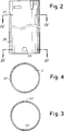
- the inner tube (26) is fitted with a grease nipple (35) housed in an aperture (37) (see Figures 2 and 4) close to the end of the inner tube to which the corresponding yoke of the universal joint (9) is applied.
- the grease nipple has a body shaped at 90°, with a section (35A) that sticks out from the exterior of the inner telescopic tube (26), and a section (35B) designed to be housed inside the protective casing.
- This section (35B) is fitted with a seat (36) in which one end of a rigid tube (39) is inserted, for reasons that are later explained. There is an aperture in this seat (36) through which the lubricant passes.
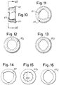
- the grease nipple (35) is connected to an end bushing (41), shown in detail in Figures 5 to 9, via the rigid tube (39). Betweeen the grease nipple (35) and the end bushing (41), there is, in the example illustrated, a ring (42) attached to the internal cylindrical surface of the inner tube (26) by drive fit welding, or other suitable means.
- the aforementioned ring (42) has an aperture through which the tube (39) passes. The tube (39) is thus held in position even when the transmission shaft is of a considerable length.
- the ring (42) limits the degree of bending of the protective casing, in as much as when the inner tube (26) bends, the ring (42) moves until it rests against the external surface of the tubular element (14) and thus limits the degree of bending of the tubes (26 and 27) of the protective casing (3).
- the end bushing (41) is constructed in two almost symetrical sections (41A and 41B) connected together via a tongue (43) fixed to the section (41A), which is inserted in a corresponding cavity (45) in the other section (41B).
- the two sections (41A and 41B) form a seat (47) into which the end of the tube (39), opposite to that connected to the grease nipple (35), is inserted and held.
- the pins (49A and 49B) are inserted into corresponding diametrically opposed apertures (53) in the tube (26) (see Figure 2).
- the bevels (51A and 51B) make it easier to insert and snap the pins (49A and 49B) into place in their respective apertures (53) thus preventing the bushing (41) from disconnecting itself from the tube (26).
- the bushing (41) rests on a support (55) that fits around the external tubular element (14) of the transmission shaft (1), and has two flanges (57 and 59) (see Figure 10), the first of which forms a rabbet resting against the tubular element (14), and the second forms a rabbet for the bushing (41).
- the shape of the support (55) depends on the transverse cross-section of the tubular elements (13 and 14) that form the telescopic connection between the universal joints (9 and 11). As a matter of fact, the coupling between the two aforementioned tubular elements can be obtained using a splined connection, but it can also be achieved using differently shaped sections.
- the flange (57) on the support (55) is of a shape that corresponds to the cross-section of the tubular element (14) to which it is fitted, and in particular, to the cross-section of the axial aperture into which the other tubular element (13) is-inserted.
- the support (55) also forms a further support point for the protective casing formed by the telescopic tubes (26 and 27), which are thus supported on the internal shaft in correspondence of the two inner yokes of the two universal joints (9 and 11), and in correspondence of an intermediate point in proximity to the end area of the outer telescopic tubular element (14).
- the end bushing (41) also has a ring-shaped groove (61) that houses a sealing ring (63), that seals it to the inner tubular element (13).
- the shape of the sealing ring (63) depends on the external shape of the inner tubular element (13) on which it must slide.
- three different shapes in which the sealing ring can be constructed are shown (63, 63X, and 63Y, respectively), to be used with various shapes of tubular elements (13 and 14).
- the shapes of the ring (63, 63X, and 63Y) are used in combination with those of the support (55, 55X, and 55Y, respectively).
- the same protective casing can be used on transmission shafts with differently shaped tubular elements (13 and 14).
- the only parts that are selected on the basis of the shape of the tubular elements (13 and 14) are the support (55) and the sealing ring (63).
- the bushing (41), support (55), and sealing ring (63) form an annular chamber into which grease is inserted via the grease nipple (35) and the tube (39).
- the aforementioned grease is heated by friction between the tubular elements (13 and 14), and is distributed by the reciprocating relative movement of the tubular elements (13 and 14); the sealing ring (63) prevents grease or oil leaking from the area where the tubular elements (13 and 14) slide.
- the sealing ring could also not seal perfectly and the resulting leak could be adjusted so that it gradually supplies a predetermined quantity of lubricant into a groove (71) on the inner yoke of the universal joint (11), in which the support elements of the protective casing (3) slide.
- the surface of the sealing ring that comes into contact with the surface of the tubular element (13) could have small protuberances or flanges placed symetrically along the tangential length of its surface in such a way as to centre the sealing ring (63) on the relative tubular element (13) without it adhering over the entire surface, so that a slight predetermined quantity of lubricant leaks out.
- this controlled leakage can easily be obtained by suitably sizing the internal protuberances (63A), so that they are slightly smaller than the corresponding grooves in the tubular element (13).
Landscapes
- Engineering & Computer Science (AREA)
- General Engineering & Computer Science (AREA)
- Mechanical Engineering (AREA)
- Sealing Devices (AREA)
- Motor Or Generator Frames (AREA)
- Rotary Pumps (AREA)
- General Details Of Gearings (AREA)
- Laminated Bodies (AREA)
- Lubricants (AREA)
- Shafts, Cranks, Connecting Bars, And Related Bearings (AREA)
- Flexible Shafts (AREA)
- Motor Power Transmission Devices (AREA)
Applications Claiming Priority (2)
| Application Number | Priority Date | Filing Date | Title |
|---|---|---|---|
| IT943390 | 1990-06-22 | ||
| IT9433A IT1241741B (it) | 1990-06-22 | 1990-06-22 | Protezione per alberi cardanici con mezzi per la lubrificazione |
Publications (2)
| Publication Number | Publication Date |
|---|---|
| EP0465440A1 true EP0465440A1 (fr) | 1992-01-08 |
| EP0465440B1 EP0465440B1 (fr) | 1994-09-14 |
Family
ID=11130078
Family Applications (1)
| Application Number | Title | Priority Date | Filing Date |
|---|---|---|---|
| EP91830270A Expired - Lifetime EP0465440B1 (fr) | 1990-06-22 | 1991-06-19 | Carter de protection pour un arbre de transmission et moyens pour sa lubrification |
Country Status (8)
| Country | Link |
|---|---|
| US (1) | US5173082A (fr) |
| EP (1) | EP0465440B1 (fr) |
| JP (1) | JPH05133424A (fr) |
| AT (1) | ATE111572T1 (fr) |
| CA (1) | CA2045083A1 (fr) |
| DE (1) | DE69103984T2 (fr) |
| ES (1) | ES2061221T3 (fr) |
| IT (1) | IT1241741B (fr) |
Cited By (6)
| Publication number | Priority date | Publication date | Assignee | Title |
|---|---|---|---|---|
| FR2697596A1 (fr) * | 1992-11-04 | 1994-05-06 | Walterscheid Gmbh Gkn | Dispositif de lubrification pour deux profils coulissants télescopiques, notamment d'un arbre de transmission. |
| AT409164B (de) * | 1997-03-22 | 2002-06-25 | Walterscheid Gmbh Gkn | Schmiervorrichtung zum schmieren der profilrohre einer teleskopwelle |
| WO2009095150A1 (fr) * | 2008-01-31 | 2009-08-06 | Voith Patent Gmbh | Arbre réglable en longueur |
| ITMO20130219A1 (it) * | 2013-07-31 | 2015-02-01 | Comer Ind Spa | Dispositivo di protezione per trasmissioni cardaniche |
| IT201700066984A1 (it) * | 2017-06-19 | 2018-12-19 | Bruno Bartolini | Protezione albero cardano con camera cross |
| WO2025199280A1 (fr) * | 2024-03-21 | 2025-09-25 | Ryan Hunter | Couvercle pour un joint de cardan d'un arbre d'entraînement |
Families Citing this family (7)
| Publication number | Priority date | Publication date | Assignee | Title |
|---|---|---|---|---|
| DE4317167C1 (de) * | 1993-05-22 | 1994-08-11 | Walterscheid Gmbh Gkn | Gelenkwelle mit verschließbarer Wartungsöffnung in Schutzrohren |
| DE19541511C1 (de) * | 1995-11-08 | 1997-04-24 | Walterscheid Gmbh Gkn | Schutzvorrichtung für Gelenkwellen mit einem abnehmbaren Schutztrichter |
| DE19541512C1 (de) * | 1995-11-08 | 1997-05-22 | Walterscheid Gmbh Gkn | Schutzvorrichtung für eine Gelenkwelle mit radialer Unterstützung des Schutztrichters |
| IT1288372B1 (it) * | 1996-11-08 | 1998-09-22 | Eurocardan S P A | Dispositivo di protezione a cuffia con ghiera con albero, in particolare albero cardanico. |
| JP3353030B2 (ja) * | 1997-11-18 | 2002-12-03 | 松井ワルターシャイド株式会社 | 駆動軸 |
| IT1314467B1 (it) * | 2000-01-07 | 2002-12-18 | Edi Bondioli | Sistema di lubrificazione a grasso, per alberi cardanici telescopicied altri complessi meccanici |
| BR112022008826A2 (pt) | 2019-11-07 | 2022-08-16 | Lea Lusetti | Junta universal com rigidez aprimorada |
Citations (5)
| Publication number | Priority date | Publication date | Assignee | Title |
|---|---|---|---|---|
| FR2139902A1 (fr) * | 1971-05-28 | 1973-01-12 | Abrahamer S | |
| DE2330286A1 (de) * | 1972-06-12 | 1974-01-03 | Dresser Ind | Kupplungsgehaeuse |
| FR2454044A1 (fr) * | 1979-04-11 | 1980-11-07 | Bondioli Edi | Dispositif de protection contre les accidents pour arbres de transmission a cardans, pourvus d'une gaine tubulaire |
| US4592556A (en) * | 1984-12-17 | 1986-06-03 | Dana Corporation | Slip joint seal assembly |
| US4605332A (en) * | 1985-04-12 | 1986-08-12 | Weasler Engineering, Inc. | Universal joint guard |
Family Cites Families (7)
| Publication number | Priority date | Publication date | Assignee | Title |
|---|---|---|---|---|
| US1612322A (en) * | 1924-07-05 | 1926-12-28 | Spicer Mfg Corp | Universal joint |
| US1645247A (en) * | 1924-08-26 | 1927-10-11 | Robert J Loock | Shim for universal joints |
| GB780930A (en) * | 1954-03-29 | 1957-08-07 | Walterscheid Gmbh Jean | A protective device for universal joint shafts coupling a driving and a driven member |
| US3080731A (en) * | 1959-12-10 | 1963-03-12 | Atkinsons Agricultural Appl | Bearing races |
| DE2327482C2 (de) * | 1973-05-30 | 1974-08-08 | Jean Walterscheid Gmbh, 5204 Lohmar | Schutzvorrichtung für Gelenkwellen |
| IT1167912B (it) * | 1981-06-05 | 1987-05-20 | Edi Bondioli | Protezione ad elementi componibili per alberi di trasmissione cardanici |
| IT1173420B (it) * | 1984-03-01 | 1987-06-24 | Benzi & Di Terlizzi Snc | Metodo di fabbricazione di un mezzo di protezione per albero di trasmissione cardanico e mezzo di protezione ottenuto col metodo |
-
1990
- 1990-06-22 IT IT9433A patent/IT1241741B/it active IP Right Grant
-
1991
- 1991-06-19 DE DE69103984T patent/DE69103984T2/de not_active Expired - Fee Related
- 1991-06-19 ES ES91830270T patent/ES2061221T3/es not_active Expired - Lifetime
- 1991-06-19 EP EP91830270A patent/EP0465440B1/fr not_active Expired - Lifetime
- 1991-06-19 AT AT91830270T patent/ATE111572T1/de not_active IP Right Cessation
- 1991-06-19 US US07/718,341 patent/US5173082A/en not_active Expired - Fee Related
- 1991-06-20 CA CA002045083A patent/CA2045083A1/fr not_active Abandoned
- 1991-06-21 JP JP3150586A patent/JPH05133424A/ja active Pending
Patent Citations (5)
| Publication number | Priority date | Publication date | Assignee | Title |
|---|---|---|---|---|
| FR2139902A1 (fr) * | 1971-05-28 | 1973-01-12 | Abrahamer S | |
| DE2330286A1 (de) * | 1972-06-12 | 1974-01-03 | Dresser Ind | Kupplungsgehaeuse |
| FR2454044A1 (fr) * | 1979-04-11 | 1980-11-07 | Bondioli Edi | Dispositif de protection contre les accidents pour arbres de transmission a cardans, pourvus d'une gaine tubulaire |
| US4592556A (en) * | 1984-12-17 | 1986-06-03 | Dana Corporation | Slip joint seal assembly |
| US4605332A (en) * | 1985-04-12 | 1986-08-12 | Weasler Engineering, Inc. | Universal joint guard |
Cited By (8)
| Publication number | Priority date | Publication date | Assignee | Title |
|---|---|---|---|---|
| FR2697596A1 (fr) * | 1992-11-04 | 1994-05-06 | Walterscheid Gmbh Gkn | Dispositif de lubrification pour deux profils coulissants télescopiques, notamment d'un arbre de transmission. |
| AT409164B (de) * | 1997-03-22 | 2002-06-25 | Walterscheid Gmbh Gkn | Schmiervorrichtung zum schmieren der profilrohre einer teleskopwelle |
| WO2009095150A1 (fr) * | 2008-01-31 | 2009-08-06 | Voith Patent Gmbh | Arbre réglable en longueur |
| ITMO20130219A1 (it) * | 2013-07-31 | 2015-02-01 | Comer Ind Spa | Dispositivo di protezione per trasmissioni cardaniche |
| EP2843251A1 (fr) * | 2013-07-31 | 2015-03-04 | Comer Industries S.p.A. | Dispositif de protection pour transmissions de joint universel |
| US9410582B2 (en) | 2013-07-31 | 2016-08-09 | Comer Industries S.P.A. | Protective device for universal joint transmissions |
| IT201700066984A1 (it) * | 2017-06-19 | 2018-12-19 | Bruno Bartolini | Protezione albero cardano con camera cross |
| WO2025199280A1 (fr) * | 2024-03-21 | 2025-09-25 | Ryan Hunter | Couvercle pour un joint de cardan d'un arbre d'entraînement |
Also Published As
| Publication number | Publication date |
|---|---|
| DE69103984T2 (de) | 1995-04-13 |
| IT1241741B (it) | 1994-02-01 |
| ATE111572T1 (de) | 1994-09-15 |
| ES2061221T3 (es) | 1994-12-01 |
| CA2045083A1 (fr) | 1991-12-23 |
| IT9009433A1 (it) | 1991-12-22 |
| US5173082A (en) | 1992-12-22 |
| IT9009433A0 (it) | 1990-06-22 |
| EP0465440B1 (fr) | 1994-09-14 |
| DE69103984D1 (de) | 1994-10-20 |
| JPH05133424A (ja) | 1993-05-28 |
Similar Documents
| Publication | Publication Date | Title |
|---|---|---|
| EP0465440B1 (fr) | Carter de protection pour un arbre de transmission et moyens pour sa lubrification | |
| CA2151425C (fr) | Raccord rapide pour conduites de fluides sous pression | |
| EP1363061B1 (fr) | Raccord de tuyaux | |
| EP0043585A1 (fr) | Connecteur optique | |
| US20030227171A1 (en) | Connection means for interconnecting two duct elements | |
| US5366043A (en) | Lubricating device for two plunging profiles slidable inside one another, especially of a propeller shaft | |
| IL37426A (en) | Connector for pipes | |
| US6508493B1 (en) | Means for connecting a pipe to a tubular body | |
| EP1201983A3 (fr) | Méthode et appareil pour l' assemblage d' accouplement pour le transfert de fluid | |
| EP0916856A3 (fr) | Arbre de transmission | |
| US20020010027A1 (en) | Wide-angle constant velocity joint with oil-bath lubrication, for universal transmissions | |
| GB1600797A (en) | Universal joint sealing elements | |
| GB2104190A (en) | Constant velocity ratio universal joint | |
| RU2180713C2 (ru) | Сочленение передачи | |
| ITRM990065A1 (it) | Dispositivo di ingrassaggio per albero telescopico con condotti assiali formati nelle sue parti tubolari relativamente scorrevoli. | |
| GB2099547A (en) | Ball type universal joint and method of manufacture | |
| US6736731B2 (en) | Cross member unit for universal joints having a trunnion seal | |
| GB2202026A (en) | Tubular conduit | |
| US20060199650A1 (en) | Centering device for mutually centering two shaft ends | |
| US6283266B1 (en) | Hydraulic clutch release mechanism | |
| US4378123A (en) | Seal means for underwater connectors | |
| US4157020A (en) | Method of and devices for lubricating rotating torque transmitting couplings | |
| GB2377256A (en) | The coupling of a drive shaft to the rotor of a progressive cavity pump | |
| GB2265688A (en) | Self-locking metal cap, for a universal joint, with a plastic bearing and lip seal | |
| US3055685A (en) | Hydraulic coupling having an internal coupling sleeve |
Legal Events
| Date | Code | Title | Description |
|---|---|---|---|
| PUAI | Public reference made under article 153(3) epc to a published international application that has entered the european phase |
Free format text: ORIGINAL CODE: 0009012 |
|
| AK | Designated contracting states |
Kind code of ref document: A1 Designated state(s): AT BE CH DE DK ES FR GB GR LI LU NL SE |
|
| 17P | Request for examination filed |
Effective date: 19920123 |
|
| 17Q | First examination report despatched |
Effective date: 19921117 |
|
| GRAA | (expected) grant |
Free format text: ORIGINAL CODE: 0009210 |
|
| AK | Designated contracting states |
Kind code of ref document: B1 Designated state(s): AT BE CH DE DK ES FR GB GR LI LU NL SE |
|
| PG25 | Lapsed in a contracting state [announced via postgrant information from national office to epo] |
Ref country code: NL Effective date: 19940914 Ref country code: LI Effective date: 19940914 Ref country code: GR Free format text: LAPSE BECAUSE OF FAILURE TO SUBMIT A TRANSLATION OF THE DESCRIPTION OR TO PAY THE FEE WITHIN THE PRESCRIBED TIME-LIMIT Effective date: 19940914 Ref country code: DK Effective date: 19940914 Ref country code: CH Effective date: 19940914 Ref country code: BE Effective date: 19940914 Ref country code: AT Effective date: 19940914 |
|
| REF | Corresponds to: |
Ref document number: 111572 Country of ref document: AT Date of ref document: 19940915 Kind code of ref document: T |
|
| REF | Corresponds to: |
Ref document number: 69103984 Country of ref document: DE Date of ref document: 19941020 |
|
| REG | Reference to a national code |
Ref country code: ES Ref legal event code: FG2A Ref document number: 2061221 Country of ref document: ES Kind code of ref document: T3 |
|
| PG25 | Lapsed in a contracting state [announced via postgrant information from national office to epo] |
Ref country code: SE Effective date: 19941214 |
|
| REG | Reference to a national code |
Ref country code: CH Ref legal event code: PL |
|
| ET | Fr: translation filed | ||
| NLV1 | Nl: lapsed or annulled due to failure to fulfill the requirements of art. 29p and 29m of the patents act | ||
| PG25 | Lapsed in a contracting state [announced via postgrant information from national office to epo] |
Ref country code: GB Effective date: 19950619 |
|
| PG25 | Lapsed in a contracting state [announced via postgrant information from national office to epo] |
Ref country code: LU Free format text: LAPSE BECAUSE OF NON-PAYMENT OF DUE FEES Effective date: 19950630 |
|
| PLBE | No opposition filed within time limit |
Free format text: ORIGINAL CODE: 0009261 |
|
| STAA | Information on the status of an ep patent application or granted ep patent |
Free format text: STATUS: NO OPPOSITION FILED WITHIN TIME LIMIT |
|
| 26N | No opposition filed | ||
| GBPC | Gb: european patent ceased through non-payment of renewal fee |
Effective date: 19950619 |
|
| PGFP | Annual fee paid to national office [announced via postgrant information from national office to epo] |
Ref country code: FR Payment date: 19960529 Year of fee payment: 6 |
|
| PGFP | Annual fee paid to national office [announced via postgrant information from national office to epo] |
Ref country code: ES Payment date: 19960610 Year of fee payment: 6 |
|
| PGFP | Annual fee paid to national office [announced via postgrant information from national office to epo] |
Ref country code: DE Payment date: 19960822 Year of fee payment: 6 |
|
| PG25 | Lapsed in a contracting state [announced via postgrant information from national office to epo] |
Ref country code: ES Free format text: LAPSE BECAUSE OF EXPIRATION OF PROTECTION Effective date: 19970620 |
|
| PG25 | Lapsed in a contracting state [announced via postgrant information from national office to epo] |
Ref country code: FR Free format text: LAPSE BECAUSE OF NON-PAYMENT OF DUE FEES Effective date: 19980227 |
|
| PG25 | Lapsed in a contracting state [announced via postgrant information from national office to epo] |
Ref country code: DE Free format text: LAPSE BECAUSE OF NON-PAYMENT OF DUE FEES Effective date: 19980303 |
|
| REG | Reference to a national code |
Ref country code: FR Ref legal event code: ST |
|
| REG | Reference to a national code |
Ref country code: FR Ref legal event code: ST |
|
| REG | Reference to a national code |
Ref country code: ES Ref legal event code: FD2A Effective date: 20000201 |