EP0465483B1 - Parapluie resistant au vent - Google Patents
Parapluie resistant au vent Download PDFInfo
- Publication number
- EP0465483B1 EP0465483B1 EP90904490A EP90904490A EP0465483B1 EP 0465483 B1 EP0465483 B1 EP 0465483B1 EP 90904490 A EP90904490 A EP 90904490A EP 90904490 A EP90904490 A EP 90904490A EP 0465483 B1 EP0465483 B1 EP 0465483B1
- Authority
- EP
- European Patent Office
- Prior art keywords
- canopy
- ribs
- vent hole
- umbrella
- post
- Prior art date
- Legal status (The legal status is an assumption and is not a legal conclusion. Google has not performed a legal analysis and makes no representation as to the accuracy of the status listed.)
- Expired - Lifetime
Links
- XLYOFNOQVPJJNP-UHFFFAOYSA-N water Substances O XLYOFNOQVPJJNP-UHFFFAOYSA-N 0.000 claims abstract description 12
- 230000002093 peripheral effect Effects 0.000 claims description 18
- 230000003014 reinforcing effect Effects 0.000 claims description 7
- 239000004744 fabric Substances 0.000 description 16
- 239000011324 bead Substances 0.000 description 9
- 239000000463 material Substances 0.000 description 7
- 230000003190 augmentative effect Effects 0.000 description 6
- 239000002982 water resistant material Substances 0.000 description 3
- 239000000853 adhesive Substances 0.000 description 2
- 230000001070 adhesive effect Effects 0.000 description 2
- 238000000034 method Methods 0.000 description 2
- 239000004677 Nylon Substances 0.000 description 1
- 230000002411 adverse Effects 0.000 description 1
- 230000005540 biological transmission Effects 0.000 description 1
- 238000004891 communication Methods 0.000 description 1
- 238000010276 construction Methods 0.000 description 1
- 238000013461 design Methods 0.000 description 1
- 239000013013 elastic material Substances 0.000 description 1
- 239000002184 metal Substances 0.000 description 1
- 238000012986 modification Methods 0.000 description 1
- 230000004048 modification Effects 0.000 description 1
- 229920001778 nylon Polymers 0.000 description 1
- 239000004033 plastic Substances 0.000 description 1
- 239000012858 resilient material Substances 0.000 description 1
- 230000000630 rising effect Effects 0.000 description 1
- 238000007789 sealing Methods 0.000 description 1
- 238000013022 venting Methods 0.000 description 1
Images



Classifications
-
- A—HUMAN NECESSITIES
- A45—HAND OR TRAVELLING ARTICLES
- A45B—WALKING STICKS; UMBRELLAS; LADIES' OR LIKE FANS
- A45B25/00—Details of umbrellas
- A45B25/18—Covers; Means for fastening same
- A45B25/20—Windows in covers
-
- A—HUMAN NECESSITIES
- A45—HAND OR TRAVELLING ARTICLES
- A45B—WALKING STICKS; UMBRELLAS; LADIES' OR LIKE FANS
- A45B25/00—Details of umbrellas
- A45B25/22—Devices for increasing the resistance of umbrellas to wind
-
- A—HUMAN NECESSITIES
- A45—HAND OR TRAVELLING ARTICLES
- A45B—WALKING STICKS; UMBRELLAS; LADIES' OR LIKE FANS
- A45B25/00—Details of umbrellas
- A45B25/18—Covers; Means for fastening same
- A45B2025/186—Umbrellas with two or more covers
Definitions
- This invention relates generally to umbrellas, and more particularly, is directed to an umbrella that is resistant to inversion from the wind.
- a windproof umbrella is disclosed in U.S. Patent No. 3,456,661 to Farley in which the main umbrella cover has a relatively large circular central opening concentric with the center pole and which may extend radially outwardly for a distance up to one-half of the dimensions of the radially oriented ribs.
- An upper umbrella covering comprised of a plurality of tapered, generally triangular gores 12 is positioned above the main umbrella covering and extends to a distance beyond the perimeter of the central hole thereof.
- Each gore is secured at its radial edges to the umbrella along the lines defined by two radially oriented ribs and has dimensions wider than the width between those ribs, the gores being secured either to the ribs or to the material of the main umbrella covering itself.
- a plurality of generally arcuate flying vents are formed which are adapted to fill with air rising from below through the central hole and expel the air horizontally when the radial ribs are rigidly held in position.
- the flying vents are adapted to collapse and form a loose covering over the central hole of the main umbrella covering to thereby shed rain in the normal fashion.
- U.S. Patent No. 3,960,162 to Noel discloses a vented umbrella. With this umbrella, openings are formed in the covering material over each rib and a rigid pivoted vent is assembled with the struts over each opening. Accordingly, during heavy winds, a large wind pressure at the underside of the umbrella will pivotally raise the vents so as to exit through the openings. However, when the vents are pivotally opened, rain can enter therethrough.
- U.S. Patent No. 3,863,660 to Glaeser discloses a method and apparatus for controlling sunlight transmission and includes an umbrella having a lower canopy with a plurality of holes throughout the canopy. In such case, the openings permit some of the sunlight to pass therebetween to the user. If it is desired that no sunlight enter the umbrella, an outer canopy or covering may be employed in covering relation to the openings. In such case, the outer canopy has a plurality of holes around the peripheral edge thereof through which the free ends or tips of the ribs can extend for holding the outer canopy in place.
- the umbrella of this patent is not intended to be used against heavy winds and is merely used as a parasol to prevent sunlight from entering. In any event, the dimensions of the outer covering are identical to those of the main canopy so that, even if such umbrella was used in rainy, windy weather, it would be difficult to exhaust the air from the space between the inner and outer canopies.
- a windproof umbrella includes a post having a lower end to be grasped by a user and an opposite upper end; a plurality of ribs extending outwardly in a radial direction from the upper end of the post, each rib having a free end; a lower canopy secured in covering relation on the ribs, the lower canopy including at least one vent hole therethrough; an upper canopy positioned over the lower canopy in covering relation to the at least one vent hole; and elastic fastening means for securing the upper canopy between the upper end of the post and the free ends of the ribs with an elastic tautness.
- a windproof umbrella in accordance with another aspect of the present invention, includes a post having a lower end to be grasped by a user and an opposite upper end; a plurality of ribs extending outwardly in a radial direction from the upper end of the post; a lower canopy secured in covering relation on the ribs, the lower canopy including at least one vent hole therethrough; channel forming means secured to the lower canopy in surrounding relation to the at least one vent hole for preventing entry of water through the at least one vent hole; and an upper canopy positioned over the lower canopy in covering relation to the at least one vent hole.
- a windproof umbrella includes a post having a lower end to be grasped by a user and an opposite upper end; a plurality of ribs extending outwardly in a radial direction from the upper end of the post; a lower canopy secured in covering relation on the ribs, the lower canopy including at least one lower vent hole therethrough; and an upper canopy positioned over the lower canopy in covering relation to the at least one lower vent hole, the upper canopy including at least one upper vent hole therethrough positioned closer to the free ends of the ribs than the at least one lower vent hole.
- a windproof umbrella includes a post having a lower end to be grasped by a user and an opposite upper end; a plurality of ribs extending outwardly in a radial direction from the upper end of the post; a lower canopy secured in covering relation on the ribs, the lower canopy including at least one vent hole therethrough; and an upper canopy positioned over the lower canopy in covering relation to the at least one vent hole, the upper canopy including an outer peripheral edge and a plurality of slits extending inwardly in a radial direction from the outer peripheral edge thereof, each slit being arranged generally in line with one rib.
- a windproof umbrella includes a post having a lower end to be grasped by a user and an opposite upper end; a plurality of ribs extending outwardly in a radial direction from the upper end of the post; a lower canopy secured in covering relation on the ribs, the lower canopy including at least one lower vent hole therethrough; bead means secured to the lower canopy in surrounding relation to the at least one lower vent hole for preventing entry of water through the at least one lower vent hole; an upper canopy positioned over the lower canopy in covering relation to the at least one lower vent hole, the upper canopy including at least one upper vent hole therethrough positioned closer to the free ends of the ribs than the at least one lower vent hole, an outer peripheral edge and a plurality of slits extending inwardly in a radial direction from the outer peripheral edge thereof, each slit being arranged generally in line with one rib; and elastic fastening means for securing the upper canopy between the upper end of the post and
- a windproof umbrella 10 includes a center post 14 having a handle 12 secured to the lower end thereof, handle 12 being adapted to be grasped by a user to carry umbrella 10 in its stored position (Fig. 4) and to hold umbrella 10 in its raised, opened position (Fig. 2).
- a stationary hub 30 is secured at the upper end of center post 14 approximately three inches from the tip thereof so as to provide an upper extension 32 which can be pointed as is conventional and depending on the style of the umbrella.
- a plurality of ribs 18 are pivotally connected to hub 30 so as to be equiangularly spaced thereabout and extend outwardly in a radial direction therefrom.
- a sleeve 15 is slidably mounted on center post 14 between handle 12 and stationary hub 30 and can be locked in an intermediate position shown in Fig. 3 by a spring biased locking tab 17, as is conventional.
- a plurality of reinforcing struts 16, equal in number to ribs 18, are provided such that each reinforcing strut 16 is pivotally secured at one end to sleeve 15 and at its opposite end to a respective rib 18 at a position substantially midway therealong.
- a lower canopy 20 is secured in covering relation on ribs 18, as is also conventional.
- Lower canopy 20 is made from a water-resistant material (such as nylon cloth) and is preferably constructed from substantially triangular cloth sectors 22 which are cut and sewn together to conform to the spaces between ribs 18. In this manner, when canopy 20 is in its untensioned state, it has an octagonal configuration.
- Canopy 20 is provided with a central opening 21 which fits tightly over hub 30, with canopy 20 preferably being secured to hub 30.
- the free end or tip 28 of each rib 18 is provided with an eyelet 24 for receiving a thread which is sewn to a corner 26 of canopy 20.
- the peripheral edge of canopy 20 is secured to free ends 28 of ribs 18.
- corners 26 of canopy 20 correspond to the seam lines between sectors 22.
- the seam between sectors 22 is preferably stitched to each rib 18 at six to eight inch intervals along its length.
- the above described arrangement is conventional.
- ribs 18 and canopy 20 assume a bowed configuration when umbrella 10 is in its fully opened position, as shown in Fig. 1.
- each vent hole 34 is provided in each canopy sector 22.
- each vent hole 34 has a substantially triangular configuration with gently surrounded corners, although the present invention is not so limited.
- each substantially triangular vent hole 34 preferably has a circumferential dimension at a base thereof of approximately four inches and a radial dimension of approximately six inches.
- an upper canopy 36 is positioned over lower canopy 20 in covering relation to vent holes 34.
- Upper canopy 36 is preferably comprised of the same water-resistant material as lower canopy 20 and is made from a corresponding number of sectors 38 as lower canopy 20.
- each sector 38 has a dimension in the radial direction of umbrella 10 which is less than that of the corresponding sector 22 of lower canopy 20.
- the seams connecting sectors 38 are preferably sewn only about one third of the radial length of each sector 38, starting from the center of upper canopy 36, thus leaving a space 44 between peripheral corners 46 of adjacent sectors 38.
- a center opening 40 is provided in upper canopy 36 and a grommet 42 is secured thereat and is swaged to sectors 38.
- Grommet 42 has a center hole and fits snugly on upper extension 32 immediately above stationary hub 30.
- a strip of elastic material 48 has opposite ends thereof sewn or otherwise attached to corners 46 of adjacent sectors 38 of upper canopy 36.
- a fastening means 50 such as a small metal grommet 52, as shown best in Fig. 5, is secured to a midpoint each elastic strip 48.
- each grommet 52 is slipped over a respective free end of a rib 18, as shown in Fig. 2. Because of the use of an elastic strip 48, upper canopy 36 is maintained in a slightly taut condition, whether umbrella 10 is in the opened position of Fig. 2 or the closed position of Fig. 4.
- a bead 57 or other channel forming member can be provided in surrounding relation to each vent hole 34.
- Such bead 57 can be made of any suitable water-resistant material and could merely be a raised surface in surrounding relation to each vent hole 34. In this manner, beads 57 provide a water channel around the outside of the vent holes 34, and prevent any water from entering vent holes 34 and falling on the user during a particularly heavy rain.
- Fig. 6a shows another embodiment of a channel forming member 57a surrounding a vent hole 34.
- a securing device 58 which is preferably made of a suitable plastic material has a generally oval configuration.
- a transverse bore 60 extends through the upper end of securing device 58 for receiving an elastic strip 48 therethrough.
- the opposite end of securing device 58 is pivotally secured to the free end or tip 28 of a respective rib 18.
- a spherical seat 62 is provided at the lower end of securing device 58 so as to fit snugly over the rounded tip 28 of a rib 18.
- a groove 64 which is in communication with spherical seat 62 extends upwardly toward transverse bore 60, but stops short thereof.
- the lower end 66 of securing device 58 is bifurcated, at 68. In this manner, the lower end 66 of securing device 58 can be biased slightly apart to receive the spherical tip 28 of a rib 18 and upon release of the separating pressure, the spherical tip 28 of such rib 18 is pivotally held captive within spherical seat 62.
- Windproof umbrella 110 is identical to windproof umbrella 10 of Figs. 1-6, with the exception that each sector 138 has a flap 70 which is adapted to overlap the adjacent sector 138 so as to completely cover space 44.
- the peripheral end of each flap 70 has a female snap element 72 at its underside which is adapted to engage a respective male snap element 74 of the adjacent sector 138 in order to secure flaps 70 in covering relation to spaces 44.
- Velcro trademark or other hook-and-loop fasteners, or other operable fasteners may be used in place of snap elements 72, 73. In such case, rather than the wind utilizing the escape path 56 shown in Fig. 3 through spaces 44, the wind 54 will tend to escape from the peripheral edge of upper canopy 136 when the flaps 70 are secured in their closed condition.
- vent holes 234 have a substantially circular or slightly oval configuration and are positioned radially inwardly with respect to vent holes 34 such that ribs 218 are substantially tangent to vent holes 234.
- upper canopy 236 includes openings 76 which are elongated in the circumferential direction thereof and are positioned radially outward from vent holes 234 when upper canopy 236 is positioned over lower canopy 220.
- Openings 76 and canopy 236 work in conjunction with vent holes 234 of lower canopy 220 to permit a maximum venting of trapped wind 254 along path 256 as shown best in Fig. 11.
- vent holes 234 can be made with a bead or channel forming member (not shown) similar to bead 57 or 57a in Figs. 6 or 6a. It will be appreciated that any rain that enters openings 76 merely falls on lower canopy 220 at a position radially outward from vent holes 234 and thereby does not enter vent holes 234.
- a windproof umbrella 310 according to yet another embodiment of the present invention will now be described, in which elements corresponding to those described above with reference to umbrella 10 of Figs. 1-6 are identified by the same reference numerals, augmented by 300, and a detailed description thereof will be omitted herein for the sake of brevity.
- the substantially triangular vertex 78 of each sector 322 is removed to form a central octagonal cutaway portion of canopy 320.
- the cutaway vertices 78 extend approximately one quarter of the distance of canopy 320 in the radial direction along the ribs from hub 330 to the free end 328 thereof. Any of the elastically connected upper canopies 36, 136 or 236 can be used therewith.
- Fig. 13 illustrates an embodiment similar to that of Figs. 1 and 2, except that the upper canopy 536 is substantially coextensive with the lower canopy 520, the end portions of the upper canopy 536 in the vicinity of the ribs 18 being connected to the ends of the ribs by means of an elastic member 546, as schematically indicated in Fig. 14.
- the elastic member 548 may take the same form as shown by elastic member 48 in Figs. 1 and 2, or make take any other suitable form, as desired.
- a critical factor is that the end portions of the upper canopy 536 in the vicinity of the ribs 18 are connected to the rib ends by means of an elastic member schematically shown at 548 so as to provide additional resiliency in the connection between the upper canopy 536 and the lower canopy 520.
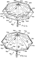
- Figs. 14 and 14A illustrate further embodiments of the invention wherein the lower portion of the upper canopy 636 is connected to the tip ends of the ribs 18 by means of elastic members 648.
- the reference numerals used in Figs. 1 and 2 are augmented by 600
- Fig. 15A the reference numerals are augmented by 700.
- Fig. 14 when wind blows from inside the umbrella, and out through the openings 634, the wind tends to separate the upper canopy 636 from the lower canopy 620.
- the elastic members 648 are connected to the upper canopy 636 at portions 649, for example by stitching.
- the elastic members 648 then pass through a small opening in the lower canopy 620 so as to pass inside of the lower canopy 620 and are then connected to the ends of the ribs 18 by means of connecting members such as shown in Fig. 5 or in other drawings of the present application.
- the small opening in the lower canopy, through which members 648 pass, is below or under the upper canopy 636 to prevent rain water from dripping therethrough.
- the ends of the elastic members 648 may be connected to end portions of the lower canopy 620 adjacent the tips of the ribs 18 by means of stitching or other adhesive or connecting means.
- the members 648 are pulled by virtue of their connection at 649 to the outer canopy 636, thereby tending to pull the tip ends of the ribs 18 inward, thus tending to prevent the ribs 18 from being blown and bent outward, thereby further preventing the undesired inversion of the umbrella due to wind.
- Fig. 14A is similar in structure, but the upper canopy 736 is substantially coextensive with the lower canopy 720.
- Connecting elements 748 are similar to connecting elements 648 in Fig. 14, and are connected to the upper canopy 736, for example by means of stitching, at 749 in Fig. 14A. Operation of this embodiment is substantially the same as that of Fig. 15, but it is presently believed by the inventors that the embodiment of Fig. 15 is more effective in preventing inversion of the umbrella because the vent holes are closer to the air exit at the perimeter of the upper layers of fabric.
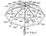
- Fig. 15 illustrates an embodiment wherein reference numerals designating the same parts as in Figs. 1 and 2 are augmented by 1,000.
- Fig. 15 includes openings 1034 similar to openings 34 of Figs. 1 and 2, but includes a plurality of flap members 1036 secured to the respective panels of the umbrella which incorporate the openings 1034 therein so as to cover the openings 1034.
- the flap members 1036 are preferably stitched to the lower canopy 1020, as shown by stitching 1037 in Fig. 15.
- the stitching 1037 preferably extends along one side of the flap 1036 and along at least a portion of the other side of the flap as shown by 1038 to improve water tightness.
- Fig. 15A illustrates a typical elastic band-type connection 1039, it being clear that other types of elastic or inelastic connections could be provided.
- the elastic connection 1039 is provided by means of a band of elastic fabric or ribbon 1050 or the like which may be stitched to the flap 1036 and to the lower canopy 1020 by means of stitching 1051 or the like.
- connection 1039 could be inelastic, in which case the connection could be stitching (or other connection) of the lower left corner of the triangular flap 1036 directly to the lower canopy 1020 or directly to the rib 18 which passes thereunder.
- This is a matter of design which may be freely chosen.
- the wind exits through the openings 1034, and passes between the flaps 1036 and the lower canopy 1020, and exits therebetween, as shown by the arrows in Fig. 15A.
- the fabric from which the flap 1036 is made is preferably very flexible and waterproof, such as a conventional umbrella canopy fabric, or can be made from a stretchable resilient material, to improve yielding thereof and the passage of air thereunder.
- stitching connections shown in Fig. 15 and 15A can be by means of ordinary thread (non-elastic) or can be by means of elastic thread, so as to provide additional resilience and yieldability, and better operability with respect to air pressure.
- adhesive connection in place of stitching
- heat sealing or other connecting technique could be used, depending upon the materials from which the inner canopy and the outer canopy and/or flaps are made. At present, stitching is preferred.
- the umbrella of Fig. 16 further comprises an inwardly directed, conical, airflow directing member at the upper part of the umbrella surrounding the center post 14.
- the reference numbers shown in Fig. 16 are the same as in Fig. 11 for the purpose of description.
- the conical shaped member 90 in Fig. 16 extends completely around the center post 14, but only half is shown in Fig. 16.
- the conical member may be made of fabric (for example the same as the fabric of the outer canopies) or any other suitable flexible and resilient sheet-like material.
- the conical member is preferably secured to the reinforcing struts 16 to provide shape.
- connection to the reinforcing struts 16 can be ties with thread or the like, or other suitable means. Since the conical shaped member 90 is made of flexible material, the umbrella can be easily folded in the same manner as a conventional umbrella. The conical shaped member 90 not only provides better directing of the air flow to the vent holes 34 or the like, but also strengthens the structure to help prevent damage thereto, especially when exposed to high winds.
- the conical member 90 of Fig. 16 can be used with any of the other embodiments shown in the drawings, as should be readily apparent. The illustration in Fig. 16 is exemplary, and is given only by way of example.
- the present invention provides various embodiments of windproof umbrellas that prevent inversion of the umbrella while also preventing rain from falling on the user.
Landscapes
- Walking Sticks, Umbrellas, And Fans (AREA)
- Holders For Apparel And Elements Relating To Apparel (AREA)
Abstract
Claims (11)
- Parapluie résistant au vent, comportant :un manche (14) ayant une extrémité inférieure (12) destinée à être saisie par un utilisateur et une extrémité supérieure opposée,plusieurs baleines (18) s'étendant vers l'extérieur dans une direction radiale à partir de ladite extrémité supérieure dudit manche (14), chaque baleine (18) ayant une extremité libre (28),une voûte inférieure (20) fixée de manière recouvrante sur lesdites baleines (18), ladite voûte inférieure (20) comportant au moins un trou d'évent (34) traversant,une voûte supérieure (36) positionnée au-dessus de ladite voûte inférieure (20) en recouvrant ledit au moins un trou d'évent (34), etdes moyens de fixation élastique (48) pour fixer ladite voûte supérieure (36) entre ladite extrémité supérieure dudit manche (14) et lesdites extrémités libres (28) desdites baleines (18) avec une raideur élastique.
- Parapluie résistant au vent selon la revendication 1,(a) comportant de plus des moyens formant moyeu (30) fixé sur l'extrémité supérieure du manche (14) pour fixer les plusieurs baleines (18) sur ladite extrémité supérieure dudit manche (14), ou(b) comportant de plus un manchon (15) positionné de manière coulissante sur ledit manche (14) entre lesdites extrémités supérieure et inférieure de celui-ci, et plusieurs traverses de renforcement (16) fixées de manière pivotante entre ledit manchon (15) et lesdites baleines (18), ou(c) dans lequel ladite voûte supérieure (36) comporte un bord périphérique et lesdits moyens de fixation élastique (48) comportent plusieurs bandes élastiques (48) reliées de manière écartée auprès dudit bord périphérique, chaque bande élastique (48) comportant des moyens de fixation de bande élastique (50) pour fixer la bande élastique respective (48) sur l'extrémité libre de l'une desdites baleines (18).
- Parapluie résistant au vent selon la revendication 2, dans lequel lesdits moyens de fixation de bande élastique (50) comportent un oeillet (52) ayant un trou à travers lequel s'étend l'extrémité libre (28) d'une baleine respective desdites baleines (18), ou dans lequel lesdits moyens de fixation de bande élastique comportent au moins des moyens de fixation (58) pour relier de manière pivotante au moins une bande élastique (48) à l'extrémité libre (48) desdites baleines (18).
- Parapluie résistant au vent selon la revendication 3, dans lequel chacun desdits moyens de fixation comporte un dispositif de fixation (58) ayant une extrémité supérieure munie d'un alésage (60) s'étendant à travers celle-ci pour recevoir une desdites bandes élastiques (48), et une extrémité inférieure reliée de manière pivotante à l'extrémité libre (28) d'une desdites baleines (18), et par exemple dans lequel l'extrémité libre de chaque baleine (18) est sphérique, et l'extrémité inférieure de chaque dispositif de fixation comporte un siège sphérique (62) pour recevoir de manière pivotante l'extrémité libre sphérique de l'une desdites baleines (18).
- Parapluie résistant au vent selon la revendication 1, dans lequel(a) ladite voûte supérieure (36) est reliée de manière détachable audit parapluie d'une manière couvrant ladite voûte inférieure (20), ou(b) ladite voûte supérieure (36) a des dimensions plus faibles que celles de ladite voûte inférieure (20).
- Parapluie résistant au vent selon l'une quelconque des revendications précédentes, comportant de plus des moyens formant canal (34) fixés sur ladite voûte inférieure (20) de manière entourant ledit au moins un trou d'évent (34) pour empêcher de plus la pénétration d'eau à travers ledit au moins un trou d'évent (34).
- Parapluie résistant au vent selon la revendication 6, dans lequel il existe plusieurs trous d'évent (34) et lesdits moyens formant canal (34) sont fixés sur ladite voûte inférieure (20) de manière entourant chaque trou d'évent (34) pour empêcher l'entrée d'eau à travers chaque trou d'évent (34).
- Parapluie résistant au vent selon l'une quelconque des revendications précédentes, dans lequel ladite voûte supérieure (36) comporte un bord périphérique extérieur et plusieurs fentes (44) s'étendant vers l'intérieur dans la direction radiale à partir du bord périphérique extérieur de celle-ci, chaque dite fente (44) étant agencée de manière générale en ligne avec une baleine (18).
- Parapluie résistant au vent selon la revendication 8, dans lequel chaque fente (44) s'étend sur une distance d'approximativement deux tiers du trajet allant du bord périphérique extérieur de ladite voûte supérieure (36) jusqu'au point central de celle-ci.
- Parapluie résistant au vent selon l'une quelconque des revendications précédentes, dans lequel ladite voûte inférieure (220) comporte au moins un trou d'évent inférieur (234) traversant et la voûte supérieure (36) est positionnée sur ladite voûte inférieure (220) d'une manière recouvrant ledit au moins un trou d'évent inférieur (234), ladite voûte supérieure (260) comportant au moins un trou d'évent supérieur (76) traversant positionné plus près desdites extrémités libres desdites baleines (18) que ledit au moins un trou d'évent inférieur (234).
- Parapluie résistant au vent selon l'une quelconque des revendications précédentes, comportant de plus un élément souple (90) de forme conique, dirigé vers l'intérieur, entourant ledit manche et agencé au niveau de l'extrémité supérieure dudit parapluie de manière à diriger l'écoulement d'air en direction dudit au moins un trou d'évent (234).
Applications Claiming Priority (3)
| Application Number | Priority Date | Filing Date | Title |
|---|---|---|---|
| US07/309,620 US4979534A (en) | 1989-02-10 | 1989-02-10 | Windproof umbrella |
| US309620 | 1989-02-10 | ||
| PCT/US1990/000796 WO1990009118A1 (fr) | 1989-02-10 | 1990-02-09 | Parapluie resistant au vent |
Publications (3)
| Publication Number | Publication Date |
|---|---|
| EP0465483A1 EP0465483A1 (fr) | 1992-01-15 |
| EP0465483A4 EP0465483A4 (en) | 1992-08-12 |
| EP0465483B1 true EP0465483B1 (fr) | 1997-05-14 |
Family
ID=23198956
Family Applications (1)
| Application Number | Title | Priority Date | Filing Date |
|---|---|---|---|
| EP90904490A Expired - Lifetime EP0465483B1 (fr) | 1989-02-10 | 1990-02-09 | Parapluie resistant au vent |
Country Status (8)
| Country | Link |
|---|---|
| US (3) | US4979534A (fr) |
| EP (1) | EP0465483B1 (fr) |
| JP (1) | JP3007141B2 (fr) |
| AU (1) | AU5185890A (fr) |
| CA (1) | CA2045471C (fr) |
| DE (1) | DE69030727T2 (fr) |
| ES (1) | ES2103736T3 (fr) |
| WO (1) | WO1990009118A1 (fr) |
Families Citing this family (76)
| Publication number | Priority date | Publication date | Assignee | Title |
|---|---|---|---|---|
| US4979534A (en) * | 1989-02-10 | 1990-12-25 | Leonard Holtz | Windproof umbrella |
| JPH04350559A (ja) * | 1991-05-28 | 1992-12-04 | Dai Ichi Pure Chem Co Ltd | 特異抗体の測定法 |
| FR2731328A1 (fr) * | 1995-03-09 | 1996-09-13 | Jacquet Alain Gerard | Parapluie sans emprise au vent |
| US5482069A (en) * | 1995-05-16 | 1996-01-09 | Lee; Chorng-Cheng | Sunshade |
| US5601103A (en) * | 1995-10-03 | 1997-02-11 | Dubinsky; Emanuel | Umbrella having partial top canopy and underside canopy connected with canopy rib sleeves to form wind vent and stabilize the ribs |
| BR9710214A (pt) * | 1996-07-06 | 2000-01-11 | Engelbert Hollah | Protetor solar. |
| DE19627766C1 (de) * | 1996-07-10 | 1997-09-18 | Ngoc Vang Dinh | Windsicherer Schirm |
| ATE271326T1 (de) | 1996-10-10 | 2004-08-15 | Innoventions Entpr Ltd | Zusammenklappbarer regenschirm mit verstärktem dachstangengestell |
| US5890506A (en) * | 1997-02-24 | 1999-04-06 | Kupferman; Glenn | Umbrella and umbrella canopy |
| US6024109A (en) * | 1998-08-03 | 2000-02-15 | Fu Tai Umbrella Works, Ltd. | Reliably controllable windproof umbrella |
| TW382921U (en) * | 1998-09-08 | 2000-02-21 | Asia Umbrella Ind Co Ltd | Structure of improved model for the umbrella |
| FR2784272A1 (fr) * | 1998-10-09 | 2000-04-14 | Camille Mounier | Parasol resistant a la brise |
| TW395197U (en) * | 1998-10-29 | 2000-06-21 | Asia Umbrella Ind Co Ltd | Improved parasol structure |
| US6095171A (en) * | 1998-11-20 | 2000-08-01 | Fu Tai Umbrella Works, Ltd. | Multiple-fold windproof umbrella with compact restoring mechanism |
| US6039063A (en) * | 1998-11-20 | 2000-03-21 | Fu Tai Umbrella Works, Ltd. | Multiple-fold windproof umbrella for preventing sagging of umbrella cloth |
| AU764771B2 (en) * | 1999-02-12 | 2003-08-28 | Gale, Dr Malcolm | Anti-inversion umbrella |
| US6089244A (en) * | 1999-02-16 | 2000-07-18 | Ko; Chin-Sung | Windproof umbrella structure |
| CN1264560A (zh) * | 2000-01-12 | 2000-08-30 | 张鸿辉 | 卸力抗强风遮雨、遮阳伞 |
| US6390108B1 (en) * | 2000-12-04 | 2002-05-21 | Fu Tai Umbrella Works Ltd. | Economic double-story umbrella |
| USD449436S1 (en) | 2001-02-02 | 2001-10-23 | Mr. Idea, Inc. | Windproof umbrella |
| US6612320B2 (en) * | 2001-06-12 | 2003-09-02 | Fu Tai Umbrella Works, Ltd. | Economic double-story umbrella as conveniently anchored |
| DE10153703C2 (de) * | 2001-10-31 | 2003-10-02 | Reinhard Voehringer | Wetterschutzvorrichtung zum Schutz von nässeempfindlichen Sonderkulturen des Pflanzenbaus |
| GB0214573D0 (en) * | 2002-06-25 | 2002-08-07 | Hall Eleanor | Umbrella with air vents |
| US20040043723A1 (en) * | 2002-09-03 | 2004-03-04 | Masoud Mafi | Baffled vent for flexible covers for outdoor use |
| US20040177872A1 (en) * | 2003-03-10 | 2004-09-16 | Yixin Guo | Releasing wind umbrella |
| US20050005958A1 (en) * | 2003-07-07 | 2005-01-13 | Connelly Kevin T. | Combination of a shade and rain umbrella |
| US20060207640A1 (en) * | 2003-07-07 | 2006-09-21 | Connelly Kevin T | Combination of a shade and rain umbrella with an emergency indication on the rain cover |
| CN2642101Y (zh) * | 2003-09-08 | 2004-09-22 | 游清泉 | 挡风自动伞 |
| USD509954S1 (en) | 2003-10-24 | 2005-09-27 | F.J. Westcott Company | Umbrella |
| US7210728B1 (en) | 2004-09-29 | 2007-05-01 | Dowco, Inc. | Vented transport cover |
| US20070256717A1 (en) * | 2005-05-18 | 2007-11-08 | Stollar Wendy A | Decorative theme slipcover for patio and beach umbrellas |
| US20060260668A1 (en) * | 2005-05-18 | 2006-11-23 | Stollar Wendy A | Decorative theme umbrella slipcover |
| US20060266396A1 (en) * | 2005-05-27 | 2006-11-30 | Perry George Jr | Windproof umbrella |
| US7581504B1 (en) * | 2005-06-17 | 2009-09-01 | Brandbrella, Llc | Printed umbrella, umbrella cover, and method of making |
| US20060289045A1 (en) * | 2005-06-27 | 2006-12-28 | Amador Ismael D | Golf club umbrella |
| US20070125409A1 (en) * | 2005-12-06 | 2007-06-07 | Debbie Colleen Cullen | Umbrella cover and related systems and methods |
| CN1989867A (zh) * | 2005-12-29 | 2007-07-04 | 游清泉 | 具单片上伞布的防风伞 |
| US7493908B2 (en) * | 2006-01-20 | 2009-02-24 | Philip R Carter | Protective umbrella for stroller |
| US7992582B2 (en) * | 2007-03-12 | 2011-08-09 | Glenn Kupferman | Umbrella and umbrella canopy |
| US20080223423A1 (en) * | 2007-03-12 | 2008-09-18 | Glenn Kupferman | Umbrella and umbrella canopy |
| US20080308139A1 (en) * | 2007-06-18 | 2008-12-18 | Keesling Jerry M | Reflective overlay for shade umbrellas |
| US20100258151A1 (en) * | 2007-08-31 | 2010-10-14 | Vogt Jeffrey A | Wind-resistant umbrella |
| US8960210B2 (en) * | 2008-01-30 | 2015-02-24 | John Andrew Bacik | Flexible umbrella systems |
| JP5285402B2 (ja) * | 2008-11-25 | 2013-09-11 | ホワイトローズ株式会社 | 傘 |
| US20100307548A1 (en) * | 2008-12-18 | 2010-12-09 | Bwbt, Llc | Collapsible Umbrella |
| US9516934B2 (en) * | 2009-09-25 | 2016-12-13 | Hubert Samuel Frost | Umbrella, and a tip element for an umbrella frame |
| US8550099B2 (en) * | 2009-10-30 | 2013-10-08 | James Ollans Essex | Sunbrella-sunscreen |
| US7980262B1 (en) | 2010-09-15 | 2011-07-19 | Ching-Chuan You | Windproof umbrella |
| ITRM20110636A1 (it) * | 2011-11-30 | 2013-05-31 | Ni Corporate S R L Sa | Elemento porta oggetti per ombrelloni |
| NO20120467A1 (no) | 2012-04-23 | 2013-10-24 | Smart Innovation As | Paraply |
| US8640720B1 (en) * | 2013-01-09 | 2014-02-04 | Glatz Ag | Large parasol with a textile fabric roof |
| US9295310B1 (en) | 2013-03-14 | 2016-03-29 | Daryl A. Smith | Identity shielding device |
| US9909336B1 (en) | 2013-03-14 | 2018-03-06 | Daryl A. Smith | Identity shielding device |
| CN104126999B (zh) * | 2013-05-02 | 2016-01-20 | 浙江泰普森创意设计有限公司 | 一种伞面和一种沙滩伞 |
| US8931496B2 (en) * | 2013-06-11 | 2015-01-13 | Andrea Elgin Beyer | Covering system |
| KR200472021Y1 (ko) * | 2014-02-04 | 2014-03-31 | 권봉선 | 복합 우산 |
| TWI565432B (zh) * | 2015-10-23 | 2017-01-11 | 劉皓銘 | 具防風效果之反折傘具 |
| US10299975B2 (en) | 2015-11-06 | 2019-05-28 | Mohammad Sayed | Wheelchair mounting systems and methods of using the same |
| US10900249B2 (en) * | 2016-02-22 | 2021-01-26 | John J. Dresch | Wind-resistant portable shade shelter |
| US9756912B1 (en) * | 2016-02-24 | 2017-09-12 | Shedrain Corporation | Wind resistant umbrella |
| US10858769B2 (en) * | 2017-01-14 | 2020-12-08 | Timothy Richard James | Sewable flange with support receiver |
| US20180228240A1 (en) * | 2017-02-13 | 2018-08-16 | Sabina Sood | Headwear system |
| US10622114B2 (en) * | 2017-03-27 | 2020-04-14 | Varian Medical Systems, Inc. | Systems and methods for energy modulated radiation therapy |
| WO2018218277A1 (fr) * | 2017-06-01 | 2018-12-06 | Derrick Leonard Henry | Dispositif de protection contre les conditions climatiques |
| US9986799B1 (en) * | 2017-08-11 | 2018-06-05 | Daniel P. King | Wind-proof dual canopy system |
| USD877484S1 (en) * | 2018-08-07 | 2020-03-10 | Jianfeng Hu | Skylight umbrella |
| USD870449S1 (en) * | 2018-09-04 | 2019-12-24 | Xiamen Sunfoo Industry Co., Ltd | Diamond-shaped double-layer umbrella |
| USD891752S1 (en) * | 2018-11-23 | 2020-08-04 | Chin-Hsing Cho | Umbrella |
| US10980321B2 (en) | 2019-08-08 | 2021-04-20 | Sol Umbra, Llc | Shade canopy |
| KR102127714B1 (ko) * | 2019-11-26 | 2020-06-29 | 임신규 | 송풍수단을 갖는 파라솔 |
| CN111887553B (zh) * | 2020-06-17 | 2025-09-16 | 宁合科技服务(南京)有限公司 | 一种户外遮阳伞 |
| JP7112114B2 (ja) * | 2020-07-10 | 2022-08-03 | テックワン株式会社 | 日傘 |
| US11766102B2 (en) * | 2020-07-31 | 2023-09-26 | Yotrio Group Co., Ltd. | Wind-resistant beach umbrella |
| USD1018017S1 (en) | 2021-10-08 | 2024-03-19 | Daniel Diaz | Multi-tier umbrella canopy |
| US12569041B2 (en) | 2022-02-11 | 2026-03-10 | Ryan R. Klespies | Wind-resistance reducing canopy structure for umbrella |
| US12029288B2 (en) | 2022-06-07 | 2024-07-09 | Jeffrey Rihn | Wind resistant parasol |
Family Cites Families (19)
| Publication number | Priority date | Publication date | Assignee | Title |
|---|---|---|---|---|
| US617415A (en) * | 1899-01-10 | Ventilated umbrella | ||
| US1031974A (en) * | 1912-05-28 | 1912-07-09 | Amos W Thomas | Umbrella. |
| US1145768A (en) * | 1914-09-16 | 1915-07-06 | Charles A Hartfiel | Umbrella. |
| US1581843A (en) * | 1924-08-22 | 1926-04-20 | Sr Thomas Francis Little | Windowed umbrella |
| AT106457B (de) * | 1926-04-16 | 1927-05-25 | Franz Jonak | Schirm. |
| US1785561A (en) * | 1928-10-31 | 1930-12-16 | Eva M Riley | Detachable cover for umbrellas |
| FR817056A (fr) * | 1936-04-27 | 1937-08-25 | Parasol avec ouvertures d'aération | |
| US2746469A (en) * | 1953-04-28 | 1956-05-22 | Andrea Neil J D | Detachable umbrella cover |
| FR1284022A (fr) * | 1960-12-30 | 1962-02-09 | Abranson | Parasol à auvents pour circulation d'air |
| US3032047A (en) * | 1961-03-01 | 1962-05-01 | Wendorf Ovaldo | Storm umbrella |
| FR1418948A (fr) * | 1964-10-13 | 1965-11-26 | Parasol | |
| US3456661A (en) * | 1967-02-13 | 1969-07-22 | Francois C Vigier | Windproof umbrella |
| US3557809A (en) * | 1969-06-26 | 1971-01-26 | Universal Umbrella Mfg Inc | Umbrella |
| US3863660A (en) * | 1972-07-21 | 1975-02-04 | Werner T Glaeser | Method and apparatus for controlling sunlight transmission |
| US3892169A (en) * | 1974-02-26 | 1975-07-01 | Frank R Jarnot | Readily installed vent for flexible cover panel |
| US3960162A (en) * | 1975-03-19 | 1976-06-01 | Francois Gilbert Noel | Vented umbrella |
| US4804008A (en) * | 1987-10-28 | 1989-02-14 | Ryder Peter M | Windproof umbrella |
| US5065779A (en) * | 1989-02-10 | 1991-11-19 | Leonard Holtz | Windproof umbrella |
| US4979534A (en) * | 1989-02-10 | 1990-12-25 | Leonard Holtz | Windproof umbrella |
-
1989
- 1989-02-10 US US07/309,620 patent/US4979534A/en not_active Expired - Lifetime
-
1990
- 1990-02-09 CA CA002045471A patent/CA2045471C/fr not_active Expired - Lifetime
- 1990-02-09 WO PCT/US1990/000796 patent/WO1990009118A1/fr not_active Ceased
- 1990-02-09 AU AU51858/90A patent/AU5185890A/en not_active Abandoned
- 1990-02-09 EP EP90904490A patent/EP0465483B1/fr not_active Expired - Lifetime
- 1990-02-09 ES ES90904490T patent/ES2103736T3/es not_active Expired - Lifetime
- 1990-02-09 US US07/730,783 patent/US5368055A/en not_active Expired - Lifetime
- 1990-02-09 DE DE69030727T patent/DE69030727T2/de not_active Expired - Lifetime
- 1990-02-09 JP JP2504347A patent/JP3007141B2/ja not_active Expired - Lifetime
-
1994
- 1994-11-15 US US08/340,079 patent/US5487401A/en not_active Expired - Lifetime
Also Published As
| Publication number | Publication date |
|---|---|
| EP0465483A4 (en) | 1992-08-12 |
| US4979534A (en) | 1990-12-25 |
| DE69030727T2 (de) | 1998-01-02 |
| CA2045471C (fr) | 1999-11-02 |
| EP0465483A1 (fr) | 1992-01-15 |
| JP3007141B2 (ja) | 2000-02-07 |
| CA2045471A1 (fr) | 1990-08-11 |
| AU5185890A (en) | 1990-09-05 |
| ES2103736T3 (es) | 1997-10-01 |
| DE69030727D1 (de) | 1997-06-19 |
| JPH04503319A (ja) | 1992-06-18 |
| WO1990009118A1 (fr) | 1990-08-23 |
| US5368055A (en) | 1994-11-29 |
| US5487401A (en) | 1996-01-30 |
Similar Documents
| Publication | Publication Date | Title |
|---|---|---|
| EP0465483B1 (fr) | Parapluie resistant au vent | |
| US5065779A (en) | Windproof umbrella | |
| US6397867B2 (en) | Vented umbrella | |
| US4865063A (en) | Wind resistive umbrella | |
| US6173724B1 (en) | Windproof umbrella (B) | |
| TWI758277B (zh) | 防風傘 | |
| US5890506A (en) | Umbrella and umbrella canopy | |
| US5601103A (en) | Umbrella having partial top canopy and underside canopy connected with canopy rib sleeves to form wind vent and stabilize the ribs | |
| US6006770A (en) | Reliably controllable windproof umbrella | |
| US5640984A (en) | Special fold-up umbrella having rib and frame design for easier opening and closing of umbrella, and two canopies designed to stabilize the ribs and vent the air | |
| AU782954B2 (en) | Insect net assembly | |
| US6237616B1 (en) | Windproof umbrella | |
| US5226438A (en) | Umbrella with special lining attached to underside of ribs to stabilize the ribs and permit easy removal of top canopy | |
| US4326301A (en) | Collapsible sunshade | |
| US4760610A (en) | Umbrella cap hat | |
| US6520193B2 (en) | Umbrella with vents on the umbrella cloth for venting wind | |
| US20100258151A1 (en) | Wind-resistant umbrella | |
| US6039063A (en) | Multiple-fold windproof umbrella for preventing sagging of umbrella cloth | |
| US6571814B2 (en) | Windproof umbrella | |
| US4131954A (en) | Collapsible headgear | |
| US6250319B1 (en) | Vented umbrella | |
| US2725066A (en) | Reversible umbrella | |
| US6170499B1 (en) | Parasol with ventilation | |
| US4300582A (en) | Storm umbrella | |
| US20040149327A1 (en) | Windproof umbrella |
Legal Events
| Date | Code | Title | Description |
|---|---|---|---|
| PUAI | Public reference made under article 153(3) epc to a published international application that has entered the european phase |
Free format text: ORIGINAL CODE: 0009012 |
|
| 17P | Request for examination filed |
Effective date: 19910910 |
|
| AK | Designated contracting states |
Kind code of ref document: A1 Designated state(s): DE ES FR GB IT |
|
| A4 | Supplementary search report drawn up and despatched |
Effective date: 19920623 |
|
| AK | Designated contracting states |
Kind code of ref document: A4 Designated state(s): DE ES FR GB IT |
|
| 17Q | First examination report despatched |
Effective date: 19931013 |
|
| GRAG | Despatch of communication of intention to grant |
Free format text: ORIGINAL CODE: EPIDOS AGRA |
|
| GRAH | Despatch of communication of intention to grant a patent |
Free format text: ORIGINAL CODE: EPIDOS IGRA |
|
| GRAH | Despatch of communication of intention to grant a patent |
Free format text: ORIGINAL CODE: EPIDOS IGRA |
|
| GRAA | (expected) grant |
Free format text: ORIGINAL CODE: 0009210 |
|
| AK | Designated contracting states |
Kind code of ref document: B1 Designated state(s): DE ES FR GB IT |
|
| REF | Corresponds to: |
Ref document number: 69030727 Country of ref document: DE Date of ref document: 19970619 |
|
| ET | Fr: translation filed | ||
| RAP4 | Party data changed (patent owner data changed or rights of a patent transferred) |
Owner name: HOLTZ, LEONARD Owner name: HOCHFELD, STANLEY Owner name: JOHNSON, GARY D. |
|
| REG | Reference to a national code |
Ref country code: ES Ref legal event code: FG2A Ref document number: 2103736 Country of ref document: ES Kind code of ref document: T3 |
|
| PLBE | No opposition filed within time limit |
Free format text: ORIGINAL CODE: 0009261 |
|
| STAA | Information on the status of an ep patent application or granted ep patent |
Free format text: STATUS: NO OPPOSITION FILED WITHIN TIME LIMIT |
|
| 26N | No opposition filed | ||
| REG | Reference to a national code |
Ref country code: GB Ref legal event code: IF02 |
|
| PGFP | Annual fee paid to national office [announced via postgrant information from national office to epo] |
Ref country code: ES Payment date: 20090212 Year of fee payment: 20 |
|
| PGFP | Annual fee paid to national office [announced via postgrant information from national office to epo] |
Ref country code: DE Payment date: 20090228 Year of fee payment: 20 |
|
| PGFP | Annual fee paid to national office [announced via postgrant information from national office to epo] |
Ref country code: GB Payment date: 20090220 Year of fee payment: 20 |
|
| PGFP | Annual fee paid to national office [announced via postgrant information from national office to epo] |
Ref country code: IT Payment date: 20090218 Year of fee payment: 20 |
|
| PGFP | Annual fee paid to national office [announced via postgrant information from national office to epo] |
Ref country code: FR Payment date: 20090225 Year of fee payment: 20 |
|
| REG | Reference to a national code |
Ref country code: GB Ref legal event code: PE20 Expiry date: 20100208 |
|
| REG | Reference to a national code |
Ref country code: ES Ref legal event code: FD2A Effective date: 20100210 |
|
| PG25 | Lapsed in a contracting state [announced via postgrant information from national office to epo] |
Ref country code: GB Free format text: LAPSE BECAUSE OF EXPIRATION OF PROTECTION Effective date: 20100208 |
|
| PG25 | Lapsed in a contracting state [announced via postgrant information from national office to epo] |
Ref country code: ES Free format text: LAPSE BECAUSE OF EXPIRATION OF PROTECTION Effective date: 20100210 |
|
| PG25 | Lapsed in a contracting state [announced via postgrant information from national office to epo] |
Ref country code: DE Free format text: LAPSE BECAUSE OF EXPIRATION OF PROTECTION Effective date: 20100209 |