EP0465607B1 - Prallauflöser - Google Patents
Prallauflöser Download PDFInfo
- Publication number
- EP0465607B1 EP0465607B1 EP90917239A EP90917239A EP0465607B1 EP 0465607 B1 EP0465607 B1 EP 0465607B1 EP 90917239 A EP90917239 A EP 90917239A EP 90917239 A EP90917239 A EP 90917239A EP 0465607 B1 EP0465607 B1 EP 0465607B1
- Authority
- EP
- European Patent Office
- Prior art keywords
- impact
- centrifuging
- detacher according
- wheel
- ducts
- Prior art date
- Legal status (The legal status is an assumption and is not a legal conclusion. Google has not performed a legal analysis and makes no representation as to the accuracy of the status listed.)
- Expired - Lifetime
Links
- 239000000463 material Substances 0.000 claims abstract description 17
- 235000013339 cereals Nutrition 0.000 claims description 7
- 235000013312 flour Nutrition 0.000 claims description 3
- 238000009434 installation Methods 0.000 description 7
- 239000000203 mixture Substances 0.000 description 7
- 241000238631 Hexapoda Species 0.000 description 6
- 230000000694 effects Effects 0.000 description 6
- 238000000034 method Methods 0.000 description 4
- 238000013461 design Methods 0.000 description 3
- 235000013601 eggs Nutrition 0.000 description 3
- 238000000926 separation method Methods 0.000 description 3
- 238000004140 cleaning Methods 0.000 description 2
- 238000010276 construction Methods 0.000 description 2
- 230000012447 hatching Effects 0.000 description 2
- 239000002245 particle Substances 0.000 description 2
- 238000012360 testing method Methods 0.000 description 2
- XLYOFNOQVPJJNP-UHFFFAOYSA-N water Substances O XLYOFNOQVPJJNP-UHFFFAOYSA-N 0.000 description 2
- 241000131102 Oryzaephilus Species 0.000 description 1
- 229910000831 Steel Inorganic materials 0.000 description 1
- 230000001133 acceleration Effects 0.000 description 1
- 230000003247 decreasing effect Effects 0.000 description 1
- 238000009826 distribution Methods 0.000 description 1
- 238000005516 engineering process Methods 0.000 description 1
- 210000003238 esophagus Anatomy 0.000 description 1
- 238000002474 experimental method Methods 0.000 description 1
- 230000001771 impaired effect Effects 0.000 description 1
- 244000005700 microbiome Species 0.000 description 1
- 230000002093 peripheral effect Effects 0.000 description 1
- 238000005293 physical law Methods 0.000 description 1
- 230000008092 positive effect Effects 0.000 description 1
- 238000004321 preservation Methods 0.000 description 1
- 230000002265 prevention Effects 0.000 description 1
- 238000012545 processing Methods 0.000 description 1
- 230000005855 radiation Effects 0.000 description 1
- 239000002994 raw material Substances 0.000 description 1
- 238000007789 sealing Methods 0.000 description 1
- 238000005204 segregation Methods 0.000 description 1
- 239000010959 steel Substances 0.000 description 1
- 238000012546 transfer Methods 0.000 description 1
- 238000009827 uniform distribution Methods 0.000 description 1
- 235000011845 white flour Nutrition 0.000 description 1
- 230000003245 working effect Effects 0.000 description 1
Images


Classifications
-
- B—PERFORMING OPERATIONS; TRANSPORTING
- B02—CRUSHING, PULVERISING, OR DISINTEGRATING; PREPARATORY TREATMENT OF GRAIN FOR MILLING
- B02C—CRUSHING, PULVERISING, OR DISINTEGRATING IN GENERAL; MILLING GRAIN
- B02C19/00—Other disintegrating devices or methods
-
- B—PERFORMING OPERATIONS; TRANSPORTING
- B02—CRUSHING, PULVERISING, OR DISINTEGRATING; PREPARATORY TREATMENT OF GRAIN FOR MILLING
- B02C—CRUSHING, PULVERISING, OR DISINTEGRATING IN GENERAL; MILLING GRAIN
- B02C13/00—Disintegrating by mills having rotary beater elements ; Hammer mills
- B02C13/14—Disintegrating by mills having rotary beater elements ; Hammer mills with vertical rotor shaft, e.g. combined with sifting devices
- B02C13/18—Disintegrating by mills having rotary beater elements ; Hammer mills with vertical rotor shaft, e.g. combined with sifting devices with beaters rigidly connected to the rotor
- B02C13/1807—Disintegrating by mills having rotary beater elements ; Hammer mills with vertical rotor shaft, e.g. combined with sifting devices with beaters rigidly connected to the rotor the material to be crushed being thrown against an anvil or impact plate
- B02C13/1835—Disintegrating by mills having rotary beater elements ; Hammer mills with vertical rotor shaft, e.g. combined with sifting devices with beaters rigidly connected to the rotor the material to be crushed being thrown against an anvil or impact plate by means of beater or impeller elements fixed in between an upper and lower rotor disc
-
- B—PERFORMING OPERATIONS; TRANSPORTING
- B02—CRUSHING, PULVERISING, OR DISINTEGRATING; PREPARATORY TREATMENT OF GRAIN FOR MILLING
- B02B—PREPARING GRAIN FOR MILLING; REFINING GRANULAR FRUIT TO COMMERCIAL PRODUCTS BY WORKING THE SURFACE
- B02B3/00—Hulling; Husking; Decorticating; Polishing; Removing the awns; Degerming
-
- B—PERFORMING OPERATIONS; TRANSPORTING
- B02—CRUSHING, PULVERISING, OR DISINTEGRATING; PREPARATORY TREATMENT OF GRAIN FOR MILLING
- B02C—CRUSHING, PULVERISING, OR DISINTEGRATING IN GENERAL; MILLING GRAIN
- B02C13/00—Disintegrating by mills having rotary beater elements ; Hammer mills
- B02C13/14—Disintegrating by mills having rotary beater elements ; Hammer mills with vertical rotor shaft, e.g. combined with sifting devices
- B02C13/18—Disintegrating by mills having rotary beater elements ; Hammer mills with vertical rotor shaft, e.g. combined with sifting devices with beaters rigidly connected to the rotor
- B02C13/1807—Disintegrating by mills having rotary beater elements ; Hammer mills with vertical rotor shaft, e.g. combined with sifting devices with beaters rigidly connected to the rotor the material to be crushed being thrown against an anvil or impact plate
- B02C13/1814—Disintegrating by mills having rotary beater elements ; Hammer mills with vertical rotor shaft, e.g. combined with sifting devices with beaters rigidly connected to the rotor the material to be crushed being thrown against an anvil or impact plate by means of beater or impeller elements fixed on top of a disc type rotor
Definitions
- the invention relates to an impact resolver for grain, semolina or flour-like material with a rotating centrifugal wheel having at least two axially offset centrifugal channels, which is surrounded by an impact ring; also a concentric feed pipe and a material discharge duct.
- impact machines are used in the mill or mill grinding. Depending on the application, these are referred to as impact resolvers, sterilizers and in the English-speaking world as Entoleters. In terms of process technology, it is partly identical, partly very similar processes. Depending on the application, the impact force or the impact speed that is exerted on the product is adjusted.
- the individual parts of the goods have a very high strength, be it the grain as a whole, as well as the semolina or flour parts.
- a grain of grain for example. was hollowed out by a grain beetle, fragile. Insects and insect eggs are very sensitive to impact. This The situation is exploited in the impact, for example by breaking hollow grains with the impact machine known as a sterilizer. Insects and insect eggs are killed.
- the regrind from a roller mill is divided into the desired fractions in the following plan sifter.
- the impact resolver is used diagrammatically between the roller mill and the plan sifter, the platelets formed during the grinding process are loosened and connected endosperm particles are loosened.
- the object of the invention was now to improve the impact machine so that a real increase in throughput is possible, but this while maintaining the quality of work or an almost 100% effectiveness, be it to render harmless insects harmless or to remove the endosperm from the shell.
- the guide apparatus is particularly preferably connected to the centrifugal wheel in a co-rotating manner.
- the guide apparatus has a plurality of feed channels which are guided into the centrifugal channels in the form of annular disks.
- the intake ducts opening into the centrifugal duct remote from the feed pipe have an installation that narrows the cross section on the outer circumference.
- the installation is designed as a ring section with a tapered shape to the axis of rotation.
- Optimal work for the impact occurs when the centrifugal wheel is designed as a double wheel and a common crop discharge channel is assigned to the twin wheel or the two impact surfaces, which ends in a tangential crop discharge channel.
- the baffles are designed with respect to the double wheel as two truncated cones that open in the opposite direction.
- the guide device has flat guide vanes both in terms of self-cleaning and for the impact effect.
- centrifugal wheel with three or four axially offset centrifugal channels when continuing the inventive idea, the more distant the centrifugal channel seen from the intake, the greater the number of intake channels should open into these, respectively. the corresponding feed area must be adjusted.
- each centrifugal channel is always assigned a separate impact ring.
- the construction costs can be kept very low if an electric drive motor is flanged directly onto the housing of the impact resolver.
- the centrifugal wheel then has the number of revolutions per minute as the electric motor, e.g. 3000 rpm.
- the material discharge channel can be formed from two halves of approximately the same shape, which can be separated in a plane perpendicular to the axis of rotation of the shaft of the centrifugal wheel.
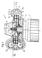
- FIG. 1 The upper part of the figure shows an impact resolver 1 as a section in the axial direction.
- An approximately 3000-speed electric motor 2 (lower half of the figure) is screwed with screws 3 and a connecting flange 4 to a lower, fixed housing part 5 of the impact resolver 1.
- the connecting flange 4 is designed such that it receives the seals for sealing the impact resolver 1 to the outside.
- An upper housing part 6 is connected to the lower housing part 5 in such a way that an impact ring 7 is firmly clamped in between. Concentric to the two housing parts 5 and 6, a feed tube 8 is placed on the upper housing part 6, through which the material to be treated is introduced into the impact resolver 1.
- a centrifugal wheel 9 is arranged in the housing parts 5 and 6. In this case, this is placed on the shaft 11 of the electric motor 2 via a carrying bush 10 and a / locking screw 12.
- the centrifugal wheel or centrifugal rotor 9 is formed by an inner turntable 13, an outer turntable 14 and a separating ring 15 arranged centrally between the two turntables 13, 14 by bolts 16 to form a double wheel or double rotor 17.
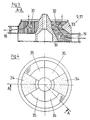
- the baffle 30 has two types of flat baffles: short baffles 31, which direct the product air flow into the inner centrifugal channel (closer to feed tube 8) 18, and long baffles 32, which direct product air flow into the outer centrifugal channel (closer to feed tube 8) 19 steer.
- the short guide plate 31 is provided with vertical hatching in FIG. 3 and the long guide plate 32 with horizontal hatching.
- the baffle 30 can be integrally e.g. in mold, and the centrifugal channels 18 and 19 made of sheet steel and both parts are connected to one unit.
- the centrifugal channel 19 is completely self-cleaning if this resp. an installation 33 in the form of a ring section is arranged in the feed area of the centrifugal channel 19 (hatched with circular rings in FIG. 4).
- a ratio of 2: 4 in relation to the number of inner feed channels 34 to the outer feed channels 35 has proven successful.
- the good-air mixture to be processed enters the feed channels via the feed pipe 8 34 resp. 35 of the nozzle 30 and is set in rotation. In the feed channels 34 respectively. 35, the mixture is accelerated and undergoes a first impact on the bolt 16.
- the water turbine-like, widening in the circumferential direction Gutabrioskanal 22 supports a uniform action on the baffle 20 or 21, and supports a reunification of air and goods, which can be transported as a mixture after the goods discharge channel 22 with a pneumatic conveyor.
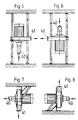
- FIG. 5 the material to be processed is fed vertically from below into the impact resolver 1 and guided away horizontally
- FIG. 6 the product feed is vertical from above.
- the raw material in FIGS. 7 and 8 enters the impact resolver 1 horizontally.
- the product transfer is vertically downwards in FIG. 7 and vertically upwards in FIG. 8.
- Fig. 9 shows a further embodiment with a triple centrifugal rotor 9, each centrifugal channel 51, respectively. 52 resp. 53 each have their own baffle 54, respectively. 55 or 56.
- the product flow is directed downward from the two baffles 55 and 56 and upward from the baffle surface 54. It is also important here that the guide apparatus 30 is designed according to the same rules as in FIGS. 1 to 4 and that a uniform product distribution is ensured for all channels.
- the centrifugal rotor 70 is designed as a 4-way rotor, analogous to FIGS. 1 to 4, with product steering in the two opposite directions by means of 4 baffle surfaces.
Landscapes
- Engineering & Computer Science (AREA)
- Food Science & Technology (AREA)
- Crushing And Pulverization Processes (AREA)
- Centrifugal Separators (AREA)
- Medicinal Preparation (AREA)
- Acyclic And Carbocyclic Compounds In Medicinal Compositions (AREA)
- Catching Or Destruction (AREA)
Priority Applications (1)
| Application Number | Priority Date | Filing Date | Title |
|---|---|---|---|
| AT90917239T ATE103509T1 (de) | 1990-01-31 | 1990-12-04 | Prallaufloeser. |
Applications Claiming Priority (2)
| Application Number | Priority Date | Filing Date | Title |
|---|---|---|---|
| CH31190 | 1990-01-31 | ||
| CH311/90 | 1990-01-31 |
Publications (2)
| Publication Number | Publication Date |
|---|---|
| EP0465607A1 EP0465607A1 (de) | 1992-01-15 |
| EP0465607B1 true EP0465607B1 (de) | 1994-03-30 |
Family
ID=4184108
Family Applications (1)
| Application Number | Title | Priority Date | Filing Date |
|---|---|---|---|
| EP90917239A Expired - Lifetime EP0465607B1 (de) | 1990-01-31 | 1990-12-04 | Prallauflöser |
Country Status (12)
| Country | Link |
|---|---|
| EP (1) | EP0465607B1 (cs) |
| JP (1) | JP2655751B2 (cs) |
| KR (1) | KR940004229B1 (cs) |
| BR (1) | BR9007242A (cs) |
| CZ (1) | CZ279161B6 (cs) |
| DE (1) | DE59005210D1 (cs) |
| ES (1) | ES2052280T3 (cs) |
| HU (1) | HU209075B (cs) |
| RU (1) | RU1837969C (cs) |
| SK (1) | SK278620B6 (cs) |
| TR (1) | TR26845A (cs) |
| WO (1) | WO1991011260A1 (cs) |
Families Citing this family (6)
| Publication number | Priority date | Publication date | Assignee | Title |
|---|---|---|---|---|
| NL1000117C2 (nl) * | 1995-04-11 | 1996-10-14 | Johannes Petrus Andreas Joseph | Rotorbladconstructie voor inslagbreker. |
| DE10154462A1 (de) * | 2001-11-08 | 2003-05-22 | Buehler Ag | Verfahren zum Isolieren von Aleuronteilchen |
| JP4289013B2 (ja) * | 2003-05-13 | 2009-07-01 | 株式会社サタケ | 穀物の衝撃式粉砕装置 |
| RU2407590C1 (ru) * | 2009-07-13 | 2010-12-27 | Валерий Львович Злочевский | Способ размола зерновых и зернистых материалов |
| RU2628340C1 (ru) * | 2013-08-13 | 2017-08-16 | Бюлер Аг | Поперечно-поточное ударное устройство |
| CN210787453U (zh) * | 2019-08-28 | 2020-06-19 | 鄂州市兴方磨具有限公司 | 一种扇形组合式碾米砂辊 |
Family Cites Families (11)
| Publication number | Priority date | Publication date | Assignee | Title |
|---|---|---|---|---|
| DE521349C (de) | 1931-03-20 | Alpine Akt Ges Eisengiesserei | Schlagstiftmuehle mit zwei zwischen zwei umlaufenden Schlagscheiben angeordneten Mahlscheiben | |
| SE168387C1 (cs) * | ||||
| DE591968C (de) * | 1930-07-25 | 1934-01-30 | Josef Otto | Schlagstiftmuehle |
| GB539883A (en) * | 1940-09-26 | 1941-09-26 | Franklin Seltzer Smith | Process and apparatus for destroying insect infestation in bulk products |
| DE923169C (de) | 1950-10-19 | 1955-02-03 | Kohlenscheidungs Ges M B H | Schlagradmuehle |
| US2928616A (en) * | 1955-09-12 | 1960-03-15 | Monda R Smith | Centrifugal impact milling machine |
| DE1026159B (de) | 1956-03-31 | 1958-03-13 | Kohlenscheidungs Ges Mit Besch | Laeufer fuer Schleudermuehlen |
| GB1013610A (en) * | 1964-11-10 | 1965-12-15 | Bath Iron Works Corp | An improved bowl for a centrifugal pulverizer |
| DE1253562B (de) | 1965-12-08 | 1967-11-02 | Miag Muehlenbau | Prall- und Schaelmuehle mit mindestens zwei um eine lotrechte Achse umlaufenden Schleuderraedern |
| CH491674A (de) * | 1968-01-12 | 1970-06-15 | Simon Ltd Henry | Stiftmühle |
| DE1814751A1 (de) * | 1968-12-14 | 1970-06-25 | Miag Muehlenbau & Ind Gmbh | Prall- und Schaelmuehle |
-
1990
- 1990-12-04 HU HU913004A patent/HU209075B/hu not_active IP Right Cessation
- 1990-12-04 DE DE90917239T patent/DE59005210D1/de not_active Expired - Fee Related
- 1990-12-04 EP EP90917239A patent/EP0465607B1/de not_active Expired - Lifetime
- 1990-12-04 KR KR1019910700825A patent/KR940004229B1/ko not_active Expired - Fee Related
- 1990-12-04 BR BR909007242A patent/BR9007242A/pt not_active IP Right Cessation
- 1990-12-04 ES ES90917239T patent/ES2052280T3/es not_active Expired - Lifetime
- 1990-12-04 JP JP3500034A patent/JP2655751B2/ja not_active Expired - Fee Related
- 1990-12-04 WO PCT/CH1990/000278 patent/WO1991011260A1/de not_active Ceased
- 1990-12-21 TR TR01228/90A patent/TR26845A/xx unknown
-
1991
- 1991-01-28 SK SK180-91A patent/SK278620B6/sk unknown
- 1991-01-28 CZ CS91180A patent/CZ279161B6/cs not_active IP Right Cessation
- 1991-09-27 RU SU915001748A patent/RU1837969C/ru active
Also Published As
| Publication number | Publication date |
|---|---|
| KR920700771A (ko) | 1992-08-10 |
| WO1991011260A1 (de) | 1991-08-08 |
| JP2655751B2 (ja) | 1997-09-24 |
| HU913004D0 (en) | 1992-02-28 |
| HU209075B (en) | 1994-03-28 |
| TR26845A (tr) | 1994-08-19 |
| SK278620B6 (en) | 1997-11-05 |
| ES2052280T3 (es) | 1994-07-01 |
| HUT61223A (en) | 1992-12-28 |
| EP0465607A1 (de) | 1992-01-15 |
| BR9007242A (pt) | 1992-03-17 |
| RU1837969C (ru) | 1993-08-30 |
| KR940004229B1 (ko) | 1994-05-19 |
| DE59005210D1 (de) | 1994-05-05 |
| CS9100180A2 (en) | 1991-09-15 |
| CZ279161B6 (cs) | 1995-01-18 |
Similar Documents
| Publication | Publication Date | Title |
|---|---|---|
| EP2632599B1 (de) | Rührwerkskugelmühle | |
| EP2637790B1 (de) | Verfahren zur zerkleinerung von mahlgut und wälzmühle | |
| EP3291915B1 (de) | Zerkleinerungsmaschine mit einem rotorsystem und verfahren zum zerkleinern von aufgabegut | |
| EP0173065A2 (de) | Wälzmühle | |
| EP0250921B1 (de) | Sichter | |
| EP1940552A1 (de) | Vorrichtung zum zerkleinern von haufwerk | |
| EP3102332B1 (de) | Rührwerkskugelmühle | |
| EP0465607B1 (de) | Prallauflöser | |
| DE2404000C2 (de) | Vorrichtung zur Aufbereitung von Gießerei-Altsand | |
| EP0764470B1 (de) | Verfahren zur Prallvermahlung und Prallmühle | |
| DE3879242T2 (de) | Feinzerkleinerungsvorrichtung. | |
| EP0791407A2 (de) | Sichter | |
| EP0692309B1 (de) | Verfahren zur Prallvermahlung und Prallmühle | |
| EP0978317B1 (de) | Gasdurchströmte Zerkleinerungsmaschine mit rotierendem Schlagradsystem | |
| DE19834896A1 (de) | Prallmühle und Verfahren zum Mahlen und Trocknen | |
| DE823481C (de) | Formasandaufbereitungsmaschine | |
| DE1253562B (de) | Prall- und Schaelmuehle mit mindestens zwei um eine lotrechte Achse umlaufenden Schleuderraedern | |
| DE3317144C1 (de) | Zuführeinrichtung für Zerkleinerungsmaschinen | |
| DE1288888B (de) | Vorrichtung zum Mahlen von stueckigem Gut | |
| DE1159744B (de) | Strahlmuehle | |
| DE830604C (de) | Prallmuehle, insbesondere zum Mahlen von Weizen und anderem Getreide | |
| DE2826553C2 (de) | Rotor für Stiftmühle zum Zerkleinern von Nahrungsmitteln | |
| DE3590172C2 (cs) | ||
| DE3012785A1 (de) | Vorrichtung zum vermahlen von schwer austragbarem saatgut bzw. mahlgut | |
| EP3106228B1 (de) | Vorrichtung und mahlwerkzeug zum zerkleinern von aufgabegut |
Legal Events
| Date | Code | Title | Description |
|---|---|---|---|
| PUAI | Public reference made under article 153(3) epc to a published international application that has entered the european phase |
Free format text: ORIGINAL CODE: 0009012 |
|
| 17P | Request for examination filed |
Effective date: 19911004 |
|
| AK | Designated contracting states |
Kind code of ref document: A1 Designated state(s): AT BE CH DE DK ES FR GB IT LI LU NL SE |
|
| 17Q | First examination report despatched |
Effective date: 19920918 |
|
| ITF | It: translation for a ep patent filed | ||
| GRAA | (expected) grant |
Free format text: ORIGINAL CODE: 0009210 |
|
| AK | Designated contracting states |
Kind code of ref document: B1 Designated state(s): AT BE CH DE DK ES FR GB IT LI LU NL SE |
|
| PG25 | Lapsed in a contracting state [announced via postgrant information from national office to epo] |
Ref country code: DK Effective date: 19940330 |
|
| REF | Corresponds to: |
Ref document number: 103509 Country of ref document: AT Date of ref document: 19940415 Kind code of ref document: T |
|
| REF | Corresponds to: |
Ref document number: 59005210 Country of ref document: DE Date of ref document: 19940505 |
|
| GBT | Gb: translation of ep patent filed (gb section 77(6)(a)/1977) |
Effective date: 19940413 |
|
| ET | Fr: translation filed | ||
| REG | Reference to a national code |
Ref country code: ES Ref legal event code: FG2A Ref document number: 2052280 Country of ref document: ES Kind code of ref document: T3 |
|
| PG25 | Lapsed in a contracting state [announced via postgrant information from national office to epo] |
Ref country code: LU Free format text: LAPSE BECAUSE OF NON-PAYMENT OF DUE FEES Effective date: 19941231 |
|
| EAL | Se: european patent in force in sweden |
Ref document number: 90917239.7 |
|
| PLBE | No opposition filed within time limit |
Free format text: ORIGINAL CODE: 0009261 |
|
| STAA | Information on the status of an ep patent application or granted ep patent |
Free format text: STATUS: NO OPPOSITION FILED WITHIN TIME LIMIT |
|
| 26N | No opposition filed | ||
| REG | Reference to a national code |
Ref country code: FR Ref legal event code: CL |
|
| REG | Reference to a national code |
Ref country code: GB Ref legal event code: IF02 |
|
| PGFP | Annual fee paid to national office [announced via postgrant information from national office to epo] |
Ref country code: NL Payment date: 20021130 Year of fee payment: 13 |
|
| PGFP | Annual fee paid to national office [announced via postgrant information from national office to epo] |
Ref country code: SE Payment date: 20021202 Year of fee payment: 13 |
|
| PGFP | Annual fee paid to national office [announced via postgrant information from national office to epo] |
Ref country code: AT Payment date: 20021204 Year of fee payment: 13 |
|
| PGFP | Annual fee paid to national office [announced via postgrant information from national office to epo] |
Ref country code: BE Payment date: 20021205 Year of fee payment: 13 |
|
| PGFP | Annual fee paid to national office [announced via postgrant information from national office to epo] |
Ref country code: ES Payment date: 20021212 Year of fee payment: 13 |
|
| PG25 | Lapsed in a contracting state [announced via postgrant information from national office to epo] |
Ref country code: AT Free format text: LAPSE BECAUSE OF NON-PAYMENT OF DUE FEES Effective date: 20031204 |
|
| PG25 | Lapsed in a contracting state [announced via postgrant information from national office to epo] |
Ref country code: SE Free format text: LAPSE BECAUSE OF NON-PAYMENT OF DUE FEES Effective date: 20031205 Ref country code: ES Free format text: LAPSE BECAUSE OF NON-PAYMENT OF DUE FEES Effective date: 20031205 |
|
| PG25 | Lapsed in a contracting state [announced via postgrant information from national office to epo] |
Ref country code: BE Free format text: LAPSE BECAUSE OF NON-PAYMENT OF DUE FEES Effective date: 20031231 |
|
| BERE | Be: lapsed |
Owner name: *BUEHLER A.G. MASCHINENFABRIK Effective date: 20031231 |
|
| PG25 | Lapsed in a contracting state [announced via postgrant information from national office to epo] |
Ref country code: NL Free format text: LAPSE BECAUSE OF NON-PAYMENT OF DUE FEES Effective date: 20040701 |
|
| EUG | Se: european patent has lapsed | ||
| NLV4 | Nl: lapsed or anulled due to non-payment of the annual fee |
Effective date: 20040701 |
|
| REG | Reference to a national code |
Ref country code: ES Ref legal event code: FD2A Effective date: 20031205 |
|
| PGFP | Annual fee paid to national office [announced via postgrant information from national office to epo] |
Ref country code: CH Payment date: 20051104 Year of fee payment: 16 |
|
| PGFP | Annual fee paid to national office [announced via postgrant information from national office to epo] |
Ref country code: DE Payment date: 20051212 Year of fee payment: 16 |
|
| PGFP | Annual fee paid to national office [announced via postgrant information from national office to epo] |
Ref country code: FR Payment date: 20051219 Year of fee payment: 16 |
|
| PGFP | Annual fee paid to national office [announced via postgrant information from national office to epo] |
Ref country code: GB Payment date: 20051222 Year of fee payment: 16 |
|
| PG25 | Lapsed in a contracting state [announced via postgrant information from national office to epo] |
Ref country code: LI Free format text: LAPSE BECAUSE OF NON-PAYMENT OF DUE FEES Effective date: 20061231 Ref country code: CH Free format text: LAPSE BECAUSE OF NON-PAYMENT OF DUE FEES Effective date: 20061231 |
|
| PGFP | Annual fee paid to national office [announced via postgrant information from national office to epo] |
Ref country code: IT Payment date: 20061231 Year of fee payment: 17 |
|
| PG25 | Lapsed in a contracting state [announced via postgrant information from national office to epo] |
Ref country code: DE Free format text: LAPSE BECAUSE OF NON-PAYMENT OF DUE FEES Effective date: 20070703 |
|
| REG | Reference to a national code |
Ref country code: CH Ref legal event code: PL |
|
| GBPC | Gb: european patent ceased through non-payment of renewal fee |
Effective date: 20061204 |
|
| REG | Reference to a national code |
Ref country code: FR Ref legal event code: ST Effective date: 20070831 |
|
| PG25 | Lapsed in a contracting state [announced via postgrant information from national office to epo] |
Ref country code: GB Free format text: LAPSE BECAUSE OF NON-PAYMENT OF DUE FEES Effective date: 20061204 |
|
| PG25 | Lapsed in a contracting state [announced via postgrant information from national office to epo] |
Ref country code: FR Free format text: LAPSE BECAUSE OF NON-PAYMENT OF DUE FEES Effective date: 20070102 |
|
| PG25 | Lapsed in a contracting state [announced via postgrant information from national office to epo] |
Ref country code: IT Free format text: LAPSE BECAUSE OF NON-PAYMENT OF DUE FEES Effective date: 20071204 |