EP0465655A1 - Hydraulic driving apparatus of civil engineering/construction equipment - Google Patents
Hydraulic driving apparatus of civil engineering/construction equipment Download PDFInfo
- Publication number
- EP0465655A1 EP0465655A1 EP90914966A EP90914966A EP0465655A1 EP 0465655 A1 EP0465655 A1 EP 0465655A1 EP 90914966 A EP90914966 A EP 90914966A EP 90914966 A EP90914966 A EP 90914966A EP 0465655 A1 EP0465655 A1 EP 0465655A1
- Authority
- EP
- European Patent Office
- Prior art keywords
- valve
- pressure
- hydraulic
- valve spool
- spool
- Prior art date
- Legal status (The legal status is an assumption and is not a legal conclusion. Google has not performed a legal analysis and makes no representation as to the accuracy of the status listed.)
- Granted
Links
Images



Classifications
-
- E—FIXED CONSTRUCTIONS
- E02—HYDRAULIC ENGINEERING; FOUNDATIONS; SOIL SHIFTING
- E02F—DREDGING; SOIL-SHIFTING
- E02F9/00—Component parts of dredgers or soil-shifting machines, not restricted to one of the kinds covered by groups E02F3/00 - E02F7/00
- E02F9/20—Drives; Control devices
- E02F9/22—Hydraulic or pneumatic drives
-
- F—MECHANICAL ENGINEERING; LIGHTING; HEATING; WEAPONS; BLASTING
- F15—FLUID-PRESSURE ACTUATORS; HYDRAULICS OR PNEUMATICS IN GENERAL
- F15B—SYSTEMS ACTING BY MEANS OF FLUIDS IN GENERAL; FLUID-PRESSURE ACTUATORS, e.g. SERVOMOTORS; DETAILS OF FLUID-PRESSURE SYSTEMS, NOT OTHERWISE PROVIDED FOR
- F15B13/00—Details of servomotor systems ; Valves for servomotor systems
- F15B13/02—Fluid distribution or supply devices characterised by their adaptation to the control of servomotors
- F15B13/04—Fluid distribution or supply devices characterised by their adaptation to the control of servomotors for use with a single servomotor
- F15B13/0416—Fluid distribution or supply devices characterised by their adaptation to the control of servomotors for use with a single servomotor with means or adapted for load sensing
- F15B13/0417—Load sensing elements; Internal fluid connections therefor; Anti-saturation or pressure-compensation valves
-
- E—FIXED CONSTRUCTIONS
- E02—HYDRAULIC ENGINEERING; FOUNDATIONS; SOIL SHIFTING
- E02F—DREDGING; SOIL-SHIFTING
- E02F9/00—Component parts of dredgers or soil-shifting machines, not restricted to one of the kinds covered by groups E02F3/00 - E02F7/00
- E02F9/20—Drives; Control devices
- E02F9/22—Hydraulic or pneumatic drives
- E02F9/2221—Control of flow rate; Load sensing arrangements
- E02F9/2232—Control of flow rate; Load sensing arrangements using one or more variable displacement pumps
-
- E—FIXED CONSTRUCTIONS
- E02—HYDRAULIC ENGINEERING; FOUNDATIONS; SOIL SHIFTING
- E02F—DREDGING; SOIL-SHIFTING
- E02F9/00—Component parts of dredgers or soil-shifting machines, not restricted to one of the kinds covered by groups E02F3/00 - E02F7/00
- E02F9/20—Drives; Control devices
- E02F9/22—Hydraulic or pneumatic drives
- E02F9/2278—Hydraulic circuits
- E02F9/2296—Systems with a variable displacement pump
-
- Y—GENERAL TAGGING OF NEW TECHNOLOGICAL DEVELOPMENTS; GENERAL TAGGING OF CROSS-SECTIONAL TECHNOLOGIES SPANNING OVER SEVERAL SECTIONS OF THE IPC; TECHNICAL SUBJECTS COVERED BY FORMER USPC CROSS-REFERENCE ART COLLECTIONS [XRACs] AND DIGESTS
- Y10—TECHNICAL SUBJECTS COVERED BY FORMER USPC
- Y10T—TECHNICAL SUBJECTS COVERED BY FORMER US CLASSIFICATION
- Y10T137/00—Fluid handling
- Y10T137/7722—Line condition change responsive valves
- Y10T137/7837—Direct response valves [i.e., check valve type]
- Y10T137/7858—With means for selecting area of valve or seat
Definitions
- the present invention relates to a hydraulic drive system for civil engineering and construction machines such as hydraulic excavators, and more particularly to a hydraulic drive system for civil engineering and construction machines which includes a pressure compensating valve to control the differential pressure across a flow control valve for controlling operation of an actuator.
- a hydraulic drive system for use in civil engineering and construction machines such as hydraulic excavators, typically called a load sensing system
- the delivery flow rate of a hydraulic pump i.e., the pump delivery rate
- the pump delivery rate is controlled so as to hold the delivery pressure of the hydraulic pump, i.e., the pump pressure, higher a fixed value than the load pressure of an actuator, causing the hydraulic pump to deliver a hydraulic fluid only at the flow rate necessary for operation of the actuator.
- the load sensing system includes a pump regulator for load sensing control (LS control), which comprises an actuator cylinder for controlling the displacement volume of the hydraulic pump, and a control valve operated responsive to the differential pressure between the pump pressure and the load pressure for controlling operation of the actuator cylinder.
- the control valve is provided with a spring for urging the control valve in a direction opposite to the differential pressure between the pump pressure and the load pressure.
- the control valve is operated so as to keep balance of a force of the spring with the differential pressure between the pump pressure and the load pressure.
- the pump delivery rate is thereby controlled such that the above differential pressure is held at a fixed value corresponding to the spring force, i.e., a target differential pressure.
- the load sensing system generally has a pressure compensating valve disposed upstream of a flow control valve to control the differential pressure across the flow control valve, thereby ensuring a flow control function to cope with fluctuations in the differential pressure between the pump pressure and the load pressure.
- the pressure compensating valve generally comprises a valve spool slidably disposed in a valve housing and having a flow control section which serves as a variable restrictor, and first and second control chambers formed in the valve housing in facing relation to each other and accommodating the opposite ends of the valve spool respectively.
- the load pressure of the actuator (the outlet pressure of the flow control valve) is introduced to the first control chamber for urging the valve spool in the valve-opening direction
- the inlet pressure of the flow control valve is introduced to the second control chamber for urging the valve spool in the valve-closing direction.
- a spring for urging the valve spool in the valve-opening direction is disposed in the first control chamber to provide a target value for the pressure compensation.
- the valve spool When the differential pressure between the inlet pressure of the flow control valve and the load pressure of the actuator respectively introduced to the first and second control chambers, i.e., the differential pressure across the flow control valve, becomes larger than the setting value of the spring, the valve spool is caused to move in the valve-closing direction so that the differential pressure across the flow control valve is controlled to be held at the setting value of the spring, i.e., the target pressure.
- the flow rate of hydraulic fluid passing through the flow control valve i.e., the flow rate of hydraulic fluid supplied to the actuator, is adjusted to a value proportional to the opening area of the flow control valve, thus permitting stable control of the actuator.
- the civil engineering and construction machine is a hydraulic excavator and the actuator is a boom cylinder for driving a boom as one component of a front mechanism
- the hydraulic fluid being subjected to inertia of the boom serves as a spring and produces a vibration. Once produced, the vibration will not damp or cease soon because damping capability of the actuator is very poor in a hydraulic system constituted by the conventional hydraulic drive system. Therefore, control accuracy of the boom cylinder is lowered, which tends to a difficulty in realizing the operation as intended by an operator.
- An object of the present invention is to provide a hydraulic drive system for civil engineering and construction machines and a pressure compensating valve for use in the system, in which the pressure compensating valve is improved to enhance damping capability of an actuator and increase control accuracy of the actuator.
- the present invention provides a hydraulic drive system for a civil engineering and construction machine comprising a hydraulic pump, an actuator driven by a hydraulic fluid delivered from said hydraulic pump, a flow control valve disposed between said hydraulic pump and said actuator, a pressure compensating valve having a valve spool for controlling a differential pressure across said flow control valve, and pump delivery rate control means for controlling a flow rate of the hydraulic fluid delivered from said hydraulic pump dependent on a differential pressure between a pump pressure and a load pressure of said actuator, said pressure compensating valve including a first control chamber subjected to the load pressure of said actuator for making the load pressure act on a first pressure receiving section of said valve spool to urge said valve spool in the valve-opening direction, a second control chamber subjected to the inlet pressure of said flow control valve for making the inlet pressure act on a second pressure receiving section of said valve spool to urge said valve spool in the valve-closing direction, and target differential pressure setting means for urging said valve spool in the valve-opening direction
- the present invention also provides a pressure compensating valve for controlling a differential pressure across a flow control valve disposed between a hydraulic pump and an actuator, the pressure compensating valve comprising a valve housing having an inlet recess connected to said hydraulic pump, an outlet recess connected to said flow control valve and a spool bore, a valve spool slidably fitted in said spool bore to control fluid communication between said inlet recess and said outlet recess, a first control chamber formed in said valve housing and subjected to a load pressure of said actuator, a first pressure receiving section disposed in said first control chamber to urge said valve spool in the valve-opening direction, a second control chamber formed in said valve spool and subjected to an inlet pressure of said flow control valve, a second pressure receiving section disposed in said second control chamber to urge said valve spool in the valve-closing direction, and target differential pressure setting means for urging said valve spool in the valve-opening direction for setting a target value of the differential pressure across said flow control
- the differential pressure across the flow control valve is given by a value resulted by subtracting a value containing the difference between the first and second pressure receiving areas as well as the load pressure from a value containing the spring force, the last value being only used in the prior art.
- This allows the flow rate of hydraulic fluid passing through the flow control valve, which is a function of the differential pressure across the flow control valve, to be expressed by a function of the value resulted by subtracting the value containing the difference in pressure receiving area and the load pressure from the value containing the spring force, i.e., a function which has a negative sign in the term containing the load pressure. Consequently, the relationship of (dQi(P)/dP) ⁇ 0 is met and the actuator can have superior damping capability. Details of this feature will be apparent from the description of preferred embodiments below.
- a hydraulic drive system of this embodiment comprises a hydraulic pump 1 of variable displacement type, an actuator driven by a hydraulic fluid delivered from the hydraulic pump 1, e.g., a boom cylinder 2 for driving a boom 2A of a hydraulic excavator, a flow control valve 5 disposed in lines 3, 4a, 4b between the hydraulic pump 1 and the boom cylinder 2 for controlling operation of the boom cylinder 2, a pressure compensating valve 8 disposed in lines upstream of the flow control valve 5, i.e., in a delivery line 6 of the hydraulic pump 1 and a line 7, for controlling the differential pressure Pz - PLS across the flow control valve 5, and a pump regulator 9 for controlling the delivery flow rate of the hydraulic pump 1, i.e., the pump delivery rate, dependent on the differential pressure Pd - PS between the pump pressure Pd and the load pressure PLS of the boom cylinder 2.
- a check valve 10 for preventing a reverse flow of the hydraulic fluid from the boom cylinder 2 is disposed in the lines 3, 7 between the flow control valve 5 and the pressure compensating valve 8.
- the inlet pressure Pz of the flow control valve 5 is taken out through a line 11 connected to the line 3, and the outlet pressure of the flow control valve 5, i.e., the load pressure PLS of the boom cylinder 2, is detected through a load line 12 connected to the flow control valve 5.
- the pump regulator 9 includes an actuator 13 coupled to a swash plate 1 a of the hydraulic pump 1 for controlling the displacement volume of the hydraulic pump 1, and a control valve 14 operated responsive to the differential pressure Pd - PLS between the pump pressure Pd and the load pressure PLS for controlling operation of the actuator 13.
- the actuator 13 is constituted by a double-acting cylinder which comprises a piston 13a with its opposite end faces having the pressure receiving or bearing areas different from each other, and a smaller-diameter cylinder chamber 13b and a larger-diameter cylinder chamber 13c located to accommodate the opposite end faces of the piston 13a, respectively.
- the smaller-diameter cylinder chamber 13b is communicated with the delivery line 6 of the hydraulic pump 1 via a line 15, while the larger-diameter cylinder chamber 13c is selectively connected to the delivery line 6 via a line 16, the control valve 14 and a line 17, or to a reservoir 19 via the line 16, the control valve 14 and a line 18.
- the control valve 14 is structured such that it has two drive parts 14a, 14b located in opposite relation, one 14a of which is subjected to the pump pressure Ps via a line 20 and the line 17 and the other 14b of which is subjected to the load pressure PLS via the load line 12. Further, a spring 14c is disposed in the control valve 14 on the same side as the drive part 14b.
- the control valve 14 When the load pressure PLS detected through the load line 12 rises, the control valve 14 is driven leftwardly on the drawing to take an illustrated position, so that the larger-diameter cylinder chamber 13c of the actuator 13 is communicated with the delivery line 6. Due to the difference in pressure receiving area between the opposite end faces of the piston 13a, the piston 13a is forced to move leftwardly on the drawing, thereby to increase the tilting amount of the swash plate 1 a, i.e., the displacement volume of the hydraulic pump 1. As a result, the pump delivery rate is increased to raise the pump pressure Pd.
- the control valve 14 Upon a rise in the pump pressure Pd, the control valve 14 is returned rightwardly on the drawing and then stopped when the differential pressure Pd - PLS reaches a target value determined by the spring 14c. At the same time, the pump delivery rate becomes constant. Conversely, when the load pressure PLS lowers, the control valve 14 is driven rightwardly on the drawing so that the larger-diameter cylinder chamber 13c is communicated with the reservoir 19. The piston 13a is thereby forced to move rightwardly on the drawing to reduce the tilting amount of the swash plate 1 a. As a result, the pump delivery rate is reduced to lower the pump pressure Pd.
- the control valve 14 Upon a decrease in the pump pressure Pd, the control valve 14 is returned leftwardly on the drawing and then stopped when the differential pressure Pd - PLS reaches the target value determined by the spring 14c. At the same time, the pump delivery rate becomes constant. Thus, the pump delivery rate is controlled such that the differential pressure Pd - PLS is held at the target differential pressure determined by the spring 14c.
- the pressure compensating valve 8 comprises a valve housing 21 which has an inlet port 21 a, an outlet port 21 b and two control ports 21 c, 21 d and also defines a spool bore 22 therein, and a valve spool 23 fitted in the spool bore 22 slidably in the axial direction.
- the valve housing 21 is also formed with annular inlet and outlet recesses 24, 25 to which the inlet and outlet ports 21a, 21 b are opened, respectively, whereas the valve spool 23 is formed in its flow control section 23a with a plurality of notches 26 which collectively constitute a variable restrictor between the inlet recess 24 and the output recess 25.
- valve housing 21 defines therein two control chambers 29, 30 in which the opposite ends of the valve spool 23 are positioned, respectively, and the hydraulic pressures in the control chambers 29, 30 act on pressure receiving sections 27, 28 formed by the opposite ends of the valve spool 23 for urging the valve spool 23 in the valve-closing direction and the valve-opening direction, respectively.
- a spring 31 is disposed in the control chamber 30. The spring 31 urges the valve spool 23 in the valve-opening direction for setting the target value of the differential pressure across the flow control valve 5 (i.e., the target value of the compensated differential pressure).
- the inlet port 21 a is connected to the delivery line 6, the output port 21 b is connected to the line 7, the control port 21 c is connected to the line 11, and the control port 21 d is connected to the load line 12.
- valve spool 23 is subjected to the inlet pressure Pz of the flow control valve 5 introduced to the control chamber 29 in the valve-closing direction, and the load pressure PLS introduced to the control chamber 30 in the valve-opening direction. Therefore, when the differential pressure between the inlet pressure Pz of the flow control valve 5 and the load pressure PLS of the boom cylinder 2, i.e., the differential pressure Pz - PLS across the flow control valve 5, becomes larger than the resilient force of the spring 31, the valve spool 23 is moved in the valve-closing direction to control the differential pressure across the flow control valve 5 so that it is held at the setting value of the spring 31, i.e., the target value.
- equation (3) indicates that the hydraulic system is an oscillating one, if; and that it is a damping one, if:
- a valve spool 45 is formed at the opposite ends thereof with pressure receiving sections 27, 46 of the same pressure receiving area.
- the pressure receiving area of the pressure receiving section 27 is Az
- the pressure receiving area of the pressure receiving section 46 is ALSO
- the relationship of Az ALSO holds.
- this embodiment can realize the relationship of ⁇ dQi(P) / dP ⁇ ⁇ 0 shown in the above equation (5) so that the boom cylinder 2 has damping capability. It is therefore possible to obtain high control accuracy of the boom cylinder 2 and achieve a superior following characteristic to operation of the boom cylinder 2 as intended by the operator.
- the means for setting a target value of the compensated differential pressure is constituted by hydraulic means in place of the spring.
- a pressure compensating valve 8A of this embodiment comprises a valve housing 21A which has two control ports 21 e, 21f, in addition to an inlet port 21 a, an outlet port 21 b and two control ports 21 c, 21 d.
- the valve housing 21 A there are defined a spool bore 22A, annular inlet and outlet recesses 24, 25, and four control chambers 29A, 30A, 50, 51.
- a valve spool 23A formed with a plurality of notches 26 is fitted in the spool bore 21 A slidably in the axial direction.
- Stepped portions are formed adjacent to the opposite ends of the valve spool 23A to provide annular pressure receiving sections 27A, 28A, respectively, and stepped portions 52, 53 are correspondingly formed in the valve housing 21A in facing relation.
- the control chambers 29A, 30A are thus defined between respective pairs of the stepped portions.
- Introduced to the control chambers 29A, 30A are the inlet pressure Pz of the flow control valve 5 and the load pressure PLS of the boom cylinder 2 via the control ports 21 c, 21 d, respectively.
- the pressure receiving area of the pressure receiving section 27A is Az
- the pressure receiving area of the pressure receiving section 28A is ALS
- Pressure receiving sections 54, 55 are formed at the opposite ends of the valve spool 23A and positioned in the control chambers 50, 51, respectively.
- the control chamber 50 is communicated with a hydraulic source 56 via the control ports 21 e, while the control chamber 51 is communicated via the control port 21f with a solenoid proportional valve 58 in turn connected to a hydraulic source 57.
- the hydraulic sources 56, 57 each produce a constant pilot pressure Pi.
- the solenoid proportional valve 58 reduces the constant pilot pressure from the hydraulic source 57 in response to an electric signal applied thereto, for generating a control pressure Pc dependent on the electric signal.
- the control force produced in the control chamber 50 with the pilot pressure Pi from the hydraulic source 56 urges the valve spool 23A in the valve-opening direction, while the control force produced in the control chamber 51 with the control pressure Pc from the solenoid proportional valve 58 urges the valve spool 23A in the valve-closing direction.
- the resulting difference between both the control forces urges the valve spool 23A in the valve-opening direction to provide a target value of the compensated differential pressure similarly to the spring 31 in the first embodiment.
- the difference between both the control forces corresponds to the resilient force f of the spring 31.
- the solenoid proportional valve 58 By controlling the solenoid proportional valve 58 to adjust the control pressure Pc, it is also possible to control the difference between both the control forces for optionally changing the target value of the compensated differential pressure.
- EP, A1, 326,150 (corresponding to JP, A, 1-312202), for example, can be applied to control of the above solenoid proportional valve.
- respective target values of the compensated differential pressure across a plurality of pressure compensating valves can properly be modified to carry out adequate flow control such as distribution control for supplying a hydraulic fluid to respective actuators reliably.
- the term AiPi - AcPc corresponds to the resilient force f of the spring 31 in the first embodiment. Therefore, the equation (12) is equivalent to the equation (7) mentioned above. As a result, the second embodiment also meets the relationship of ⁇ dQ(P)/dP ⁇ ⁇ 0 and can provide the similar advantageous effect to that in the foregoing first embodiment.
- the target value of the compensated differential pressure is set by a combination of a spring and hydraulic means.
- a pressure compensating valve 8B of this embodiment is constituted such that a spring 31 B is disposed in a chamber 50B instead of the hydraulic source 56 in the second embodiment shown Fig. 4, and a resilient force f of the spring 31 B is produced to act on the valve spool 23B in the valve-opening direction.
- the chamber 50 is connected to a drain circuit 59 in communication with a reservoir.
- the rest of the pressure compensating valve 8B is constituted in a like manner to that of the second embodiment.
- the term f - AcPc in the equation (14) represents a force acting to urge the valve spool 23B in the valve-opening direction and corresponds to the initial load f of the spring 31 in the first embodiment. Therefore, the equation (14) is likewise equivalent to the equation (7) mentioned above. As a result, the third embodiment also meets the relationship of ⁇ dQi(P)/dP ⁇ ⁇ 0 and can provide the similar advantageous effect to that in the foregoing first embodiment.
- an actuator can be given with damping capability. It is thus possible to obtain high control accuracy of the actuator, achieve a superior following characteristic to operation by an operator, and ensure superior operability without letting the operator to feel fatigued.
Landscapes
- Engineering & Computer Science (AREA)
- General Engineering & Computer Science (AREA)
- Mining & Mineral Resources (AREA)
- Civil Engineering (AREA)
- Structural Engineering (AREA)
- Physics & Mathematics (AREA)
- Fluid Mechanics (AREA)
- Mechanical Engineering (AREA)
- Fluid-Pressure Circuits (AREA)
- Operation Control Of Excavators (AREA)
Abstract
Description
- The present invention relates to a hydraulic drive system for civil engineering and construction machines such as hydraulic excavators, and more particularly to a hydraulic drive system for civil engineering and construction machines which includes a pressure compensating valve to control the differential pressure across a flow control valve for controlling operation of an actuator.
- There is known a hydraulic drive system for use in civil engineering and construction machines such as hydraulic excavators, typically called a load sensing system, that the delivery flow rate of a hydraulic pump, i.e., the pump delivery rate, is controlled so as to hold the delivery pressure of the hydraulic pump, i.e., the pump pressure, higher a fixed value than the load pressure of an actuator, causing the hydraulic pump to deliver a hydraulic fluid only at the flow rate necessary for operation of the actuator. As disclosed in JP, A, 60-11706, for example, the load sensing system includes a pump regulator for load sensing control (LS control), which comprises an actuator cylinder for controlling the displacement volume of the hydraulic pump, and a control valve operated responsive to the differential pressure between the pump pressure and the load pressure for controlling operation of the actuator cylinder. The control valve is provided with a spring for urging the control valve in a direction opposite to the differential pressure between the pump pressure and the load pressure. The control valve is operated so as to keep balance of a force of the spring with the differential pressure between the pump pressure and the load pressure. The pump delivery rate is thereby controlled such that the above differential pressure is held at a fixed value corresponding to the spring force, i.e., a target differential pressure.
- Furthermore, the load sensing system generally has a pressure compensating valve disposed upstream of a flow control valve to control the differential pressure across the flow control valve, thereby ensuring a flow control function to cope with fluctuations in the differential pressure between the pump pressure and the load pressure.
- The pressure compensating valve generally comprises a valve spool slidably disposed in a valve housing and having a flow control section which serves as a variable restrictor, and first and second control chambers formed in the valve housing in facing relation to each other and accommodating the opposite ends of the valve spool respectively. The load pressure of the actuator (the outlet pressure of the flow control valve) is introduced to the first control chamber for urging the valve spool in the valve-opening direction, and the inlet pressure of the flow control valve is introduced to the second control chamber for urging the valve spool in the valve-closing direction. A spring for urging the valve spool in the valve-opening direction is disposed in the first control chamber to provide a target value for the pressure compensation.
- When the differential pressure between the inlet pressure of the flow control valve and the load pressure of the actuator respectively introduced to the first and second control chambers, i.e., the differential pressure across the flow control valve, becomes larger than the setting value of the spring, the valve spool is caused to move in the valve-closing direction so that the differential pressure across the flow control valve is controlled to be held at the setting value of the spring, i.e., the target pressure. As a result of the differential pressure across the flow control valve being controlled in this way, the flow rate of hydraulic fluid passing through the flow control valve, i.e., the flow rate of hydraulic fluid supplied to the actuator, is adjusted to a value proportional to the opening area of the flow control valve, thus permitting stable control of the actuator.
- One pressure compensating valve of this type is disclosed in U.S. Patent No. 4,688,600, for example.
- However, the hydraulic drive system equipped with the above conventional pressure compensating value has accompanied a problem as follows.
- In the case where the civil engineering and construction machine is a hydraulic excavator and the actuator is a boom cylinder for driving a boom as one component of a front mechanism, for example, when the flow control valve is quickly operated to change a drive speed of the boom cylinder during operation of the boom cylinder, the hydraulic fluid being subjected to inertia of the boom serves as a spring and produces a vibration. Once produced, the vibration will not damp or cease soon because damping capability of the actuator is very poor in a hydraulic system constituted by the conventional hydraulic drive system. Therefore, control accuracy of the boom cylinder is lowered, which tends to a difficulty in realizing the operation as intended by an operator.
- An object of the present invention is to provide a hydraulic drive system for civil engineering and construction machines and a pressure compensating valve for use in the system, in which the pressure compensating valve is improved to enhance damping capability of an actuator and increase control accuracy of the actuator.
- To achieve the above object, the present invention provides a hydraulic drive system for a civil engineering and construction machine comprising a hydraulic pump, an actuator driven by a hydraulic fluid delivered from said hydraulic pump, a flow control valve disposed between said hydraulic pump and said actuator, a pressure compensating valve having a valve spool for controlling a differential pressure across said flow control valve, and pump delivery rate control means for controlling a flow rate of the hydraulic fluid delivered from said hydraulic pump dependent on a differential pressure between a pump pressure and a load pressure of said actuator, said pressure compensating valve including a first control chamber subjected to the load pressure of said actuator for making the load pressure act on a first pressure receiving section of said valve spool to urge said valve spool in the valve-opening direction, a second control chamber subjected to the inlet pressure of said flow control valve for making the inlet pressure act on a second pressure receiving section of said valve spool to urge said valve spool in the valve-closing direction, and target differential pressure setting means for urging said valve spool in the valve-opening direction for setting a target value of the differential pressure across said flow control valve, wherein a pressure receiving area of said second pressure receiving section is set greater than a pressure receiving area of said first pressure receiving section.
- The present invention also provides a pressure compensating valve for controlling a differential pressure across a flow control valve disposed between a hydraulic pump and an actuator, the pressure compensating valve comprising a valve housing having an inlet recess connected to said hydraulic pump, an outlet recess connected to said flow control valve and a spool bore, a valve spool slidably fitted in said spool bore to control fluid communication between said inlet recess and said outlet recess, a first control chamber formed in said valve housing and subjected to a load pressure of said actuator, a first pressure receiving section disposed in said first control chamber to urge said valve spool in the valve-opening direction, a second control chamber formed in said valve spool and subjected to an inlet pressure of said flow control valve, a second pressure receiving section disposed in said second control chamber to urge said valve spool in the valve-closing direction, and target differential pressure setting means for urging said valve spool in the valve-opening direction for setting a target value of the differential pressure across said flow control valve, wherein a pressure receiving area of said second pressure receiving section is set greater than a pressure receiving area of said first pressure receiving section.
- With the present invention thus constituted, the differential pressure across the flow control valve is given by a value resulted by subtracting a value containing the difference between the first and second pressure receiving areas as well as the load pressure from a value containing the spring force, the last value being only used in the prior art. This allows the flow rate of hydraulic fluid passing through the flow control valve, which is a function of the differential pressure across the flow control valve, to be expressed by a function of the value resulted by subtracting the value containing the difference in pressure receiving area and the load pressure from the value containing the spring force, i.e., a function which has a negative sign in the term containing the load pressure. Consequently, the relationship of (dQi(P)/dP) < 0 is met and the actuator can have superior damping capability. Details of this feature will be apparent from the description of preferred embodiments below.
-
- Fig. 1 is a schematic view of a hydraulic drive system according to a first embodiment of the present invention.
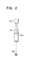
- Fig. 2 is a view for explaining a vibration produced in a hydraulic cylinder conventionally in a well-known manner.
- Fig. 3 is a schematic view of a conventional hydraulic drive system.
- Fig. 4 is a schematic view of a hydraulic drive system according to a second embodiment of the present invention.
- Fig. 5 is a schematic view of a hydraulic drive system according to a third embodiment of the present invention.
- Hereinafter, several preferred embodiments of the present invention will be described with reference to the drawings.
- At the outset, a first embodiment of the present invention will be described with reference to Fig. 1.
- In Fig. 1, a hydraulic drive system of this embodiment comprises a
hydraulic pump 1 of variable displacement type, an actuator driven by a hydraulic fluid delivered from thehydraulic pump 1, e.g., aboom cylinder 2 for driving aboom 2A of a hydraulic excavator, aflow control valve 5 disposed inlines hydraulic pump 1 and theboom cylinder 2 for controlling operation of theboom cylinder 2, a pressure compensating valve 8 disposed in lines upstream of theflow control valve 5, i.e., in a delivery line 6 of thehydraulic pump 1 and aline 7, for controlling the differential pressure Pz - PLS across theflow control valve 5, and apump regulator 9 for controlling the delivery flow rate of thehydraulic pump 1, i.e., the pump delivery rate, dependent on the differential pressure Pd - PS between the pump pressure Pd and the load pressure PLS of theboom cylinder 2. Acheck valve 10 for preventing a reverse flow of the hydraulic fluid from theboom cylinder 2 is disposed in thelines flow control valve 5 and the pressure compensating valve 8. The inlet pressure Pz of theflow control valve 5 is taken out through a line 11 connected to theline 3, and the outlet pressure of theflow control valve 5, i.e., the load pressure PLS of theboom cylinder 2, is detected through aload line 12 connected to theflow control valve 5. - The
pump regulator 9 includes anactuator 13 coupled to a swash plate 1 a of thehydraulic pump 1 for controlling the displacement volume of thehydraulic pump 1, and acontrol valve 14 operated responsive to the differential pressure Pd - PLS between the pump pressure Pd and the load pressure PLS for controlling operation of theactuator 13. Theactuator 13 is constituted by a double-acting cylinder which comprises apiston 13a with its opposite end faces having the pressure receiving or bearing areas different from each other, and a smaller-diameter cylinder chamber 13b and a larger-diameter cylinder chamber 13c located to accommodate the opposite end faces of thepiston 13a, respectively. The smaller-diameter cylinder chamber 13b is communicated with the delivery line 6 of thehydraulic pump 1 via aline 15, while the larger-diameter cylinder chamber 13c is selectively connected to the delivery line 6 via aline 16, thecontrol valve 14 and aline 17, or to areservoir 19 via theline 16, thecontrol valve 14 and aline 18. Thecontrol valve 14 is structured such that it has twodrive parts 14a, 14b located in opposite relation, one 14a of which is subjected to the pump pressure Ps via aline 20 and theline 17 and the other 14b of which is subjected to the load pressure PLS via theload line 12. Further, aspring 14c is disposed in thecontrol valve 14 on the same side as thedrive part 14b. - When the load pressure PLS detected through the
load line 12 rises, thecontrol valve 14 is driven leftwardly on the drawing to take an illustrated position, so that the larger-diameter cylinder chamber 13c of theactuator 13 is communicated with the delivery line 6. Due to the difference in pressure receiving area between the opposite end faces of thepiston 13a, thepiston 13a is forced to move leftwardly on the drawing, thereby to increase the tilting amount of the swash plate 1 a, i.e., the displacement volume of thehydraulic pump 1. As a result, the pump delivery rate is increased to raise the pump pressure Pd. Upon a rise in the pump pressure Pd, thecontrol valve 14 is returned rightwardly on the drawing and then stopped when the differential pressure Pd - PLS reaches a target value determined by thespring 14c. At the same time, the pump delivery rate becomes constant. Conversely, when the load pressure PLS lowers, thecontrol valve 14 is driven rightwardly on the drawing so that the larger-diameter cylinder chamber 13c is communicated with thereservoir 19. Thepiston 13a is thereby forced to move rightwardly on the drawing to reduce the tilting amount of the swash plate 1 a. As a result, the pump delivery rate is reduced to lower the pump pressure Pd. Upon a decrease in the pump pressure Pd, thecontrol valve 14 is returned leftwardly on the drawing and then stopped when the differential pressure Pd - PLS reaches the target value determined by thespring 14c. At the same time, the pump delivery rate becomes constant. Thus, the pump delivery rate is controlled such that the differential pressure Pd - PLS is held at the target differential pressure determined by thespring 14c. - The pressure compensating valve 8 comprises a
valve housing 21 which has aninlet port 21 a, an outlet port 21 b and twocontrol ports 21 c, 21 d and also defines aspool bore 22 therein, and avalve spool 23 fitted in the spool bore 22 slidably in the axial direction. Thevalve housing 21 is also formed with annular inlet andoutlet recesses outlet ports 21a, 21 b are opened, respectively, whereas thevalve spool 23 is formed in itsflow control section 23a with a plurality ofnotches 26 which collectively constitute a variable restrictor between the inlet recess 24 and the output recess 25. - Further, the
valve housing 21 defines therein twocontrol chambers valve spool 23 are positioned, respectively, and the hydraulic pressures in thecontrol chambers pressure receiving sections valve spool 23 for urging thevalve spool 23 in the valve-closing direction and the valve-opening direction, respectively. In addition, aspring 31 is disposed in thecontrol chamber 30. Thespring 31 urges thevalve spool 23 in the valve-opening direction for setting the target value of the differential pressure across the flow control valve 5 (i.e., the target value of the compensated differential pressure). - The
inlet port 21 a is connected to the delivery line 6, the output port 21 b is connected to theline 7, thecontrol port 21 c is connected to the line 11, and the control port 21 d is connected to theload line 12. - Moreover, in the pressure compensating valve 8 of this embodiment, a
stepped portion 32 is formed adjacent to the end of thevalve spool 23 on the same side as thepressure receiving section 28, and astepped portion 33 is correspondingly formed in thevalve housing 21 in facing relation, so that assuming that the pressure receiving area of thepressure receiving section 27 is Az and the pressure receiving area of thepressure receiving section 28 is ALS, the pressure receiving area Az is made smaller than the pressure receiving area ALS. Therefore, the relationship of Az - ALS = AA > 0 holds. Then, achamber 34 defined between the twostepped portions drain circuit 35 in communication with the reservoir so that no pressure will act on thechamber 34. - In the hydraulic drive system thus constituted, when the
flow control valve 5 is at a neutral position, thevalve spool 23 is moved leftwardly on the drawing by the action of thespring 31 so that the pressure compensating valve 8 is fully opened. At this time, the swash plate 1 a of thehydraulic pump 1 is held at a minimum tilting position by thepump regulator 9. - Under such a condition, when the
flow control valve 5 is operated in the valve-opening direction from the neutral position, the hydraulic fluid delivered form thehydraulic pump 1 is supplied to theboom cylinder 2 through the pressure compensating valve 8 and theflow control valve 5, whereupon thepump regulator 9 is operated to increase the pump delivery rate, as mentioned above, so that theboom cylinder 2 is extended or contracted to ascent or descent theboom 2A about afulcrum 36. On this occasion, the inlet pressure Pz of theflow control valve 5 and the load pressure PLS of theboom cylinder 2 are introduced to thecontrol chambers lines 11, 12, respectively. Thus, thevalve spool 23 is subjected to the inlet pressure Pz of theflow control valve 5 introduced to thecontrol chamber 29 in the valve-closing direction, and the load pressure PLS introduced to thecontrol chamber 30 in the valve-opening direction. Therefore, when the differential pressure between the inlet pressure Pz of theflow control valve 5 and the load pressure PLS of theboom cylinder 2, i.e., the differential pressure Pz - PLS across theflow control valve 5, becomes larger than the resilient force of thespring 31, thevalve spool 23 is moved in the valve-closing direction to control the differential pressure across theflow control valve 5 so that it is held at the setting value of thespring 31, i.e., the target value. As a result of that the differential pressure across theflow control valve 5 is controlled in this way, if the opening area of theflow control valve 5 remains fixed, the flow rate of hydraulic fluid passing through theflow control valve 5, i.e., the flow rate of hydraulic fluid supplied to theboom cylinder 2, becomes almost constant, making it possible to perform stable control of theboom cylinder 2. - The foregoing is related to the general operation of the hydraulic drive system including the pressure compensating valve 8. The operation specific to the pressure compensating valve 8 of this embodiment will be explained below.
- First, let it to take consideration of damping characteristics in a typical cylinder system in which, as shown in Fig. 2, a hydraulic fluid is supplied from a
hydraulic source 40 to ahydraulic cylinder 41 for driving aload 42. In Fig. 2, assuming that; - mass of the load 42 : m
- displacement due to operation of the hydraulic cylinder 41 : x
- operating speed of the hydraulic cylinder 41:
- acceleration of the hydraulic cylinder 41: x
- acceleration of gravity : g
- pressure in a bottom chamber of the hydraulic cylinder 41: P
- change rate of the pressure P : P
- flow rate supplied to the hydraulic cylinder 41: Qi(P)
- pressure receiving area of a piston 41 a of the hydraulic cylinder 41: A
- volume of the bottom chamber of the hydraulic cylinder 41: V
- volume modulus of the hydraulic fluid led to the bottom chamber of the hydraulic cylinder 41: K
- there hold the following equations:

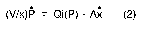
- Elimination of x, x from the equations (1), (2) leads to:

- From the well-known theory, the equation (3) indicates that the hydraulic system is an oscillating one, if;


- Based on the foregoing background, now consider the hydraulic drive system equipped with a conventional pressure compensating valve shown in Fig. 3. In a conventional
pressure compensating valve 43, avalve spool 45 is formed at the opposite ends thereof withpressure receiving sections pressure receiving section 27 is Az and the pressure receiving area of thepressure receiving section 46 is ALSO, the relationship of Az = ALSO holds. In such an arrangement, given the resilient force of thespring 31, i.e., the initial load, being f, the differential pressure across theflow control valve 5 is controlled so as to meet the relationship of Az(Pz - PLS) = f. Accordingly, if the opening area of theflow control valve 5 remains fixed, the flow rate Qi(P) of hydraulic fluid passing through theflow control valve 5, which is a function of the differential pressure across it, becomes constant and expressed by:
- This equation (6) indicates that once produced, the vibration will not be damped and last as a free vibration. Actually, the damping coefficient inside the
boom cylinder 2 is small and the damping capability is very poor. - Stated otherwise, when the
flow control valve 5 is quickly operated during operation of theboom cylinder 2, a vibration is produced in theboom cylinder 2, which lowers control accuracy of the boom cylinder because of very poor damping capability. This tends to a difficulty in realizing the operation as intended by an operator. - In contrast, with this embodiment, assuming that the pressure receiving areas of the
pressure receiving sections valve spool 23 are respectively Az , ALS, and the resilient force of thespring 31 is f, as mentioned above, the following equation holds from balance of the respective forces acting on the valve spool 23:
- Taking into account Az - ALS = AA, the equation (7) can be rewritten to:

- Accordingly, letting the opening area of the
flow control valve 5 be a and c be a constant, the flow rate of hydraulic fluid supplied to theboom cylinder 2 is expressed by:
- Differentiation of the equation (9) leads to:
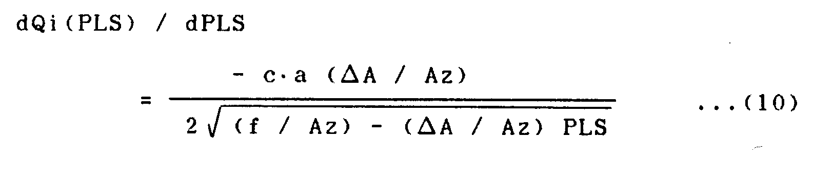
- Since the term AA in the right side of the equation (10) is given by AA > 0, the relationship of {dQi(P) / dP} < 0 is resulted to provide damping capability as mentioned above.
- Consequently, this embodiment can realize the relationship of {dQi(P) / dP} < 0 shown in the above equation (5) so that the
boom cylinder 2 has damping capability. It is therefore possible to obtain high control accuracy of theboom cylinder 2 and achieve a superior following characteristic to operation of theboom cylinder 2 as intended by the operator. - A second embodiment of the present invention will be described with reference to Fig. 4. In this embodiment, the means for setting a target value of the compensated differential pressure is constituted by hydraulic means in place of the spring.
- In Fig. 4, a
pressure compensating valve 8A of this embodiment comprises avalve housing 21A which has twocontrol ports 21 e, 21f, in addition to aninlet port 21 a, an outlet port 21 b and twocontrol ports 21 c, 21 d. In thevalve housing 21 A, there are defined aspool bore 22A, annular inlet and outlet recesses 24, 25, and fourcontrol chambers valve spool 23A formed with a plurality ofnotches 26 is fitted in the spool bore 21 A slidably in the axial direction. - Stepped portions are formed adjacent to the opposite ends of the
valve spool 23A to provide annularpressure receiving sections portions valve housing 21A in facing relation. Thecontrol chambers control chambers flow control valve 5 and the load pressure PLS of theboom cylinder 2 via thecontrol ports 21 c, 21 d, respectively. Assuming that the pressure receiving area of thepressure receiving section 27A is Az and the pressure receiving area of thepressure receiving section 28A is ALS, the relationship between these pressure receiving areas is expressed by Az - ALS = AA > 0, as with the first embodiment. -
Pressure receiving sections valve spool 23A and positioned in thecontrol chambers control chamber 50 is communicated with ahydraulic source 56 via the control ports 21 e, while thecontrol chamber 51 is communicated via thecontrol port 21f with a solenoidproportional valve 58 in turn connected to ahydraulic source 57. - The
hydraulic sources proportional valve 58 reduces the constant pilot pressure from thehydraulic source 57 in response to an electric signal applied thereto, for generating a control pressure Pc dependent on the electric signal. The control force produced in thecontrol chamber 50 with the pilot pressure Pi from thehydraulic source 56 urges thevalve spool 23A in the valve-opening direction, while the control force produced in thecontrol chamber 51 with the control pressure Pc from the solenoidproportional valve 58 urges thevalve spool 23A in the valve-closing direction. The resulting difference between both the control forces urges thevalve spool 23A in the valve-opening direction to provide a target value of the compensated differential pressure similarly to thespring 31 in the first embodiment. Thus, the difference between both the control forces corresponds to the resilient force f of thespring 31. By controlling the solenoidproportional valve 58 to adjust the control pressure Pc, it is also possible to control the difference between both the control forces for optionally changing the target value of the compensated differential pressure. - In addition, the invention of EP, A1, 326,150 (corresponding to JP, A, 1-312202), for example, can be applied to control of the above solenoid proportional valve. With such an application, when a hydraulic pump is saturated in a hydraulic drive system for driving a plurality of actuators, respective target values of the compensated differential pressure across a plurality of pressure compensating valves can properly be modified to carry out adequate flow control such as distribution control for supplying a hydraulic fluid to respective actuators reliably.
- In the second embodiment thus constituted, the following equation holds from balance of the respective forces acting on the
valve spool 23A:
- This equation (11) can be rewritten to:

- Here, the term AiPi - AcPc corresponds to the resilient force f of the
spring 31 in the first embodiment. Therefore, the equation (12) is equivalent to the equation (7) mentioned above. As a result, the second embodiment also meets the relationship of {dQ(P)/dP} < 0 and can provide the similar advantageous effect to that in the foregoing first embodiment. - A third embodiment of the present invention will be described with reference to Fig. 5. In this embodiment, the target value of the compensated differential pressure is set by a combination of a spring and hydraulic means.
- In Fig. 5, a
pressure compensating valve 8B of this embodiment is constituted such that a spring 31 B is disposed in achamber 50B instead of thehydraulic source 56 in the second embodiment shown Fig. 4, and a resilient force f of the spring 31 B is produced to act on thevalve spool 23B in the valve-opening direction. Thechamber 50 is connected to adrain circuit 59 in communication with a reservoir. The rest of thepressure compensating valve 8B is constituted in a like manner to that of the second embodiment. - In the third embodiment thus constituted, the following equation holds from balance of the respective forces acting on the
valve spool 23B:
- This equation (13) can be rewritten to:

- Here, the term f - AcPc in the equation (14) represents a force acting to urge the
valve spool 23B in the valve-opening direction and corresponds to the initial load f of thespring 31 in the first embodiment. Therefore, the equation (14) is likewise equivalent to the equation (7) mentioned above. As a result, the third embodiment also meets the relationship of {dQi(P)/dP} < 0 and can provide the similar advantageous effect to that in the foregoing first embodiment. - According to the present invention, since the relationship of {dQi(P)/dP} < 0 is met, an actuator can be given with damping capability. It is thus possible to obtain high control accuracy of the actuator, achieve a superior following characteristic to operation by an operator, and ensure superior operability without letting the operator to feel fatigued.
Claims (6)
Applications Claiming Priority (3)
| Application Number | Priority Date | Filing Date | Title |
|---|---|---|---|
| JP263022/89 | 1989-10-11 | ||
| JP26302289 | 1989-10-11 | ||
| PCT/JP1990/001310 WO1991005958A1 (en) | 1989-10-11 | 1990-10-11 | Hydraulic driving apparatus of civil engineering/construction equipment |
Publications (3)
| Publication Number | Publication Date |
|---|---|
| EP0465655A1 true EP0465655A1 (en) | 1992-01-15 |
| EP0465655A4 EP0465655A4 (en) | 1992-03-04 |
| EP0465655B1 EP0465655B1 (en) | 1995-10-11 |
Family
ID=17383795
Family Applications (1)
| Application Number | Title | Priority Date | Filing Date |
|---|---|---|---|
| EP90914966A Expired - Lifetime EP0465655B1 (en) | 1989-10-11 | 1990-10-11 | Hydraulic driving apparatus of civil engineering/construction equipment |
Country Status (6)
| Country | Link |
|---|---|
| US (1) | US5152140A (en) |
| EP (1) | EP0465655B1 (en) |
| JP (1) | JP3194384B2 (en) |
| KR (1) | KR950004532B1 (en) |
| DE (1) | DE69022985T2 (en) |
| WO (1) | WO1991005958A1 (en) |
Cited By (1)
| Publication number | Priority date | Publication date | Assignee | Title |
|---|---|---|---|---|
| EP0707151A3 (en) * | 1994-10-10 | 1997-11-19 | Trinova Limited | An hydraulic circuit controlling an actuator |
Families Citing this family (14)
| Publication number | Priority date | Publication date | Assignee | Title |
|---|---|---|---|---|
| US5271227A (en) * | 1990-05-15 | 1993-12-21 | Kabushiki Kaisha Komatsu Seisakusho | Hydraulic apparatus with pressure compensating valves |
| FR2694606B1 (en) * | 1992-08-04 | 1994-11-04 | Bennes Marrel | Control assembly for a plurality of hydraulic receivers. |
| US5454223A (en) * | 1993-05-28 | 1995-10-03 | Dana Corporation | Hydraulic load sensing system with poppet valve having an orifice therein |
| SE510508C2 (en) * | 1993-06-11 | 1999-05-31 | Voac Hydraulics Boraas Ab | Device for controlling a hydraulic motor |
| SE501289C2 (en) * | 1993-06-24 | 1995-01-09 | Voac Hydraulics Boraas Ab | Controls for a hydraulic motor |
| JPH07127607A (en) * | 1993-09-07 | 1995-05-16 | Yutani Heavy Ind Ltd | Hydraulic device of work machine |
| JP3853123B2 (en) * | 1998-12-03 | 2006-12-06 | 日立建機株式会社 | Hydraulic drive |
| JP4155811B2 (en) * | 2002-12-13 | 2008-09-24 | 株式会社小松製作所 | Differential pressure adjustment valve |
| US20100158706A1 (en) * | 2008-12-24 | 2010-06-24 | Caterpillar Inc. | Pressure change compensation arrangement for pump actuator |
| AU2010256864B2 (en) * | 2009-06-02 | 2015-01-22 | National Oilwell Varco L.P. | Hydraulic oilfield lift pump |
| US20120224977A1 (en) * | 2011-03-04 | 2012-09-06 | Sotz Leonard C | Method and Apparatus for Fluid Pumping |
| CN102296665B (en) * | 2011-06-23 | 2013-04-24 | 上海三一重机有限公司 | Excavator hydraulic system carrying load sensing main valve and positive flow pump |
| JP6250898B2 (en) * | 2015-07-29 | 2017-12-20 | 株式会社アドヴィックス | Hydraulic pressure generator |
| KR102060988B1 (en) * | 2017-11-22 | 2020-02-11 | 한국기계연구원 | Pressure-compensated proportional flow control valve |
Family Cites Families (14)
| Publication number | Priority date | Publication date | Assignee | Title |
|---|---|---|---|---|
| GB652362A (en) * | 1947-02-11 | 1951-04-25 | Prec Developments Co Ltd | Improvements relating to hydraulic power transmission apparatus |
| US3230841A (en) * | 1963-08-30 | 1966-01-25 | Ray A York | Constant speed control for hydraulic motors |
| US3777773A (en) * | 1972-02-22 | 1973-12-11 | Koehring Co | Pressure compensating valve mechanism |
| US3987623A (en) * | 1976-01-23 | 1976-10-26 | Caterpillar Tractor Co. | Controlled priority fluid system of a crawler type vehicle |
| US4196588A (en) * | 1978-05-01 | 1980-04-08 | Caterpillar Tractor Co. | Margin valve |
| JPS57177406A (en) * | 1981-04-25 | 1982-11-01 | Daikin Ind Ltd | Combind flow type flow control circuit capable of mode exchange |
| JPS5813202A (en) * | 1981-07-14 | 1983-01-25 | Daikin Ind Ltd | Flow control device with pressure compensation |
| DE3321483A1 (en) * | 1983-06-14 | 1984-12-20 | Linde Ag, 6200 Wiesbaden | HYDRAULIC DEVICE WITH ONE PUMP AND AT LEAST TWO OF THESE INACTED CONSUMERS OF HYDRAULIC ENERGY |
| US4794846A (en) * | 1985-02-23 | 1989-01-03 | Barmag Ag | Proportional action valve with a biased spring unproportionately variable to the load pressure |
| DE3507121A1 (en) * | 1985-02-28 | 1986-08-28 | Mannesmann Rexroth GmbH, 8770 Lohr | MULTI-WAY VALVE WITH PRESSURE SCALE |
| DE3522450A1 (en) * | 1985-06-22 | 1987-01-02 | Bosch Gmbh Robert | Hydraulic device for actuating an adjusting part |
| DE3536218A1 (en) * | 1985-10-10 | 1987-04-16 | Heilmeier & Weinlein | Two-way flow controller |
| IN171213B (en) * | 1988-01-27 | 1992-08-15 | Hitachi Construction Machinery | |
| JPH0786361B2 (en) * | 1988-11-10 | 1995-09-20 | 株式会社ゼクセル | Hydraulic control valve |
-
1990
- 1990-10-11 DE DE69022985T patent/DE69022985T2/en not_active Expired - Fee Related
- 1990-10-11 WO PCT/JP1990/001310 patent/WO1991005958A1/en not_active Ceased
- 1990-10-11 KR KR1019910700304A patent/KR950004532B1/en not_active Expired - Fee Related
- 1990-10-11 EP EP90914966A patent/EP0465655B1/en not_active Expired - Lifetime
- 1990-10-11 JP JP51397290A patent/JP3194384B2/en not_active Expired - Fee Related
- 1990-10-11 US US07/640,440 patent/US5152140A/en not_active Expired - Lifetime
Cited By (1)
| Publication number | Priority date | Publication date | Assignee | Title |
|---|---|---|---|---|
| EP0707151A3 (en) * | 1994-10-10 | 1997-11-19 | Trinova Limited | An hydraulic circuit controlling an actuator |
Also Published As
| Publication number | Publication date |
|---|---|
| DE69022985D1 (en) | 1995-11-16 |
| US5152140A (en) | 1992-10-06 |
| EP0465655A4 (en) | 1992-03-04 |
| EP0465655B1 (en) | 1995-10-11 |
| JP3194384B2 (en) | 2001-07-30 |
| WO1991005958A1 (en) | 1991-05-02 |
| DE69022985T2 (en) | 1996-03-21 |
| KR920701583A (en) | 1992-08-12 |
| KR950004532B1 (en) | 1995-05-02 |
Similar Documents
| Publication | Publication Date | Title |
|---|---|---|
| EP0465655B1 (en) | Hydraulic driving apparatus of civil engineering/construction equipment | |
| KR960006358B1 (en) | Hydraulic driving system and direction change-over valves | |
| US5134853A (en) | Hydraulic drive system for construction machines | |
| EP0423353B1 (en) | Hydraulic driving apparatus of caterpillar vehicle | |
| KR970000243B1 (en) | Hydraulically driving system | |
| US6209321B1 (en) | Hydraulic controller for a working machine | |
| US5186000A (en) | Hydraulic drive system for construction machines | |
| EP0427865B1 (en) | Hydraulic driving device of construction equipment | |
| EP0394465A1 (en) | Hydraulic driving apparatus | |
| US5528911A (en) | Hydraulic control apparatus for a plurality of users | |
| EP0477370A1 (en) | Valve device and hydraulic driving device | |
| JPWO1991005958A1 (en) | Hydraulic drive units for civil engineering and construction machinery | |
| US4938022A (en) | Flow control system for hydraulic motors | |
| KR100314778B1 (en) | Pressure compensating valves | |
| JP3241837B2 (en) | Hydraulic drive | |
| JP2860158B2 (en) | Hydraulic drive for civil and construction machinery | |
| JP2963162B2 (en) | Multiple control valve device | |
| JP3356250B2 (en) | Hunting prevention circuit for construction machinery | |
| JPH03153901A (en) | Hydraulic drive device for civil engineering and construction machine | |
| KR920006661B1 (en) | Hydraulic drive unit for construction machinery | |
| JP3162203B2 (en) | Valve device | |
| JP3074012B2 (en) | Multiple control valve device | |
| JPWO1990013748A1 (en) | Hydraulic drive units for civil engineering and construction machinery | |
| JPS6138201A (en) | Control device for counterbalance valve | |
| JPH0456885B2 (en) |
Legal Events
| Date | Code | Title | Description |
|---|---|---|---|
| PUAI | Public reference made under article 153(3) epc to a published international application that has entered the european phase |
Free format text: ORIGINAL CODE: 0009012 |
|
| 17P | Request for examination filed |
Effective date: 19910214 |
|
| AK | Designated contracting states |
Kind code of ref document: A1 Designated state(s): DE FR GB IT SE |
|
| A4 | Supplementary search report drawn up and despatched |
Effective date: 19920117 |
|
| AK | Designated contracting states |
Kind code of ref document: A4 Designated state(s): DE FR GB IT SE |
|
| 17Q | First examination report despatched |
Effective date: 19930923 |
|
| GRAA | (expected) grant |
Free format text: ORIGINAL CODE: 0009210 |
|
| RBV | Designated contracting states (corrected) |
Designated state(s): DE GB IT |
|
| AK | Designated contracting states |
Kind code of ref document: B1 Designated state(s): DE GB IT |
|
| REF | Corresponds to: |
Ref document number: 69022985 Country of ref document: DE Date of ref document: 19951116 |
|
| ITF | It: translation for a ep patent filed | ||
| PLBE | No opposition filed within time limit |
Free format text: ORIGINAL CODE: 0009261 |
|
| STAA | Information on the status of an ep patent application or granted ep patent |
Free format text: STATUS: NO OPPOSITION FILED WITHIN TIME LIMIT |
|
| 26N | No opposition filed | ||
| REG | Reference to a national code |
Ref country code: GB Ref legal event code: IF02 |
|
| PGFP | Annual fee paid to national office [announced via postgrant information from national office to epo] |
Ref country code: DE Payment date: 20061005 Year of fee payment: 17 |
|
| PGFP | Annual fee paid to national office [announced via postgrant information from national office to epo] |
Ref country code: GB Payment date: 20061011 Year of fee payment: 17 |
|
| PGFP | Annual fee paid to national office [announced via postgrant information from national office to epo] |
Ref country code: IT Payment date: 20061031 Year of fee payment: 17 |
|
| GBPC | Gb: european patent ceased through non-payment of renewal fee |
Effective date: 20071011 |
|
| PG25 | Lapsed in a contracting state [announced via postgrant information from national office to epo] |
Ref country code: DE Free format text: LAPSE BECAUSE OF NON-PAYMENT OF DUE FEES Effective date: 20080501 |
|
| PG25 | Lapsed in a contracting state [announced via postgrant information from national office to epo] |
Ref country code: GB Free format text: LAPSE BECAUSE OF NON-PAYMENT OF DUE FEES Effective date: 20071011 |
|
| PG25 | Lapsed in a contracting state [announced via postgrant information from national office to epo] |
Ref country code: IT Free format text: LAPSE BECAUSE OF NON-PAYMENT OF DUE FEES Effective date: 20071011 |