EP0465658A1 - Antenne helicoidale a enroulement a nombre fractionnaire et a quatre fils - Google Patents
Antenne helicoidale a enroulement a nombre fractionnaire et a quatre fils Download PDFInfo
- Publication number
- EP0465658A1 EP0465658A1 EP91900334A EP91900334A EP0465658A1 EP 0465658 A1 EP0465658 A1 EP 0465658A1 EP 91900334 A EP91900334 A EP 91900334A EP 91900334 A EP91900334 A EP 91900334A EP 0465658 A1 EP0465658 A1 EP 0465658A1
- Authority
- EP
- European Patent Office
- Prior art keywords
- antenna
- helical antenna
- winding helical
- wire fractional
- wire
- Prior art date
- Legal status (The legal status is an assumption and is not a legal conclusion. Google has not performed a legal analysis and makes no representation as to the accuracy of the status listed.)
- Granted
Links
Images




Classifications
-
- H—ELECTRICITY
- H01—ELECTRIC ELEMENTS
- H01Q—ANTENNAS, i.e. RADIO AERIALS
- H01Q11/00—Electrically-long antennas having dimensions more than twice the shortest operating wavelength and consisting of conductive active radiating elements
- H01Q11/02—Non-resonant antennas, e.g. travelling-wave antenna
- H01Q11/08—Helical antennas
Definitions
- the present invention relates to a 4-wire fractional-winding helical antenna whose helical conductors can be formed easily and precisely by the photoetching technology and to the method for manufacturing it.
- the present invention also relates to a 4-wire fractional-winding helical antenna unit which can prevent the decrease of the gain and the deterioration of the directivity caused by the effect of the reflected wave by the components at the antenna base.
- a 4-wire fractional-winding helical antenna has been attracting attention as an antenna used in communication systems using geostationay or non-stationary satellites and is used widely.
- Figure 11 is a sectional view showing a 4-wire fractional-winding helical antenna unit heretofore used in such communication systems.
- the antenna unit comprises a balun 103 mounted on a base plate 101, an antenna supported above the balun 103 and a hybrid circuit 105 (HYB) located below the base plate 101 and is housed in a radome 102 secured to the base plate 101.
- a hybrid circuit 105 HYB
- the antenna comprises a mylar member 106 formed in a cylinder and two antenna elements 107 and 108 helically wound around the mylar member 106 as shown in Figure 12. The bottom ends of these antenna elements 107 and 108 are connected to the four terminals of the balun 103.
- the balun 103 is a part for an unbalanced-balanced conversion between the hybrid circuit 105 and each antenna element 107, 108, whose bottom terminals are connected to the hybrid circuit 105 by means of a coaxial cable passed through the base plate 101.
- the hybrid circuit 105 generates two signals with a predetermined phase difference fed from the signal from a transceiver in an aircraft to send them to the balun 103, and combines the signals fed from the antenna via the balun 103 to send the resultant signal to the transceiver.
- the frequency bandwidth of the above cylindrical 4-wire fractional-winding antenna 104 is not sufficiently broad for simultaneous transmission and reception through two separate frequency bands with one antenna as shown in Figures 13 (b) and (c).
- Figure 13 (a) shows the dimensions of the above single-cylinder 4-wire fractional-winding antenna 104.
- Figures 13 (b) and (c) show the standing wave ratio (SWR) measured at each of the two input terminals of the balun 105.
- the antenna of this example has the dimensions as shown in Figure 13 (a) and its antenna elements (conductor pattern on the side surface of the mylar member) are formed so that the antenna can be used for two frequency bands 1.53 to 1.56 GHz and 1.63 to 1.66 GHz.
- the frequency characteristics of the SWRs measured at the two input terminals of the balun are different due to manufacturing errors, variation in the quality of the material and other causes, though it is desired that they are identical.
- the conventional antenna in Figure 13 (a) is not satisfactory from this aspect, because the SWR of the above conventional antenna exceeds the desirable limit, that is, the SWR in Figure 13 (b) is 2.2 at 1.66 GHz and that in Figure 13 (c) is 1.8 at 1.66 GHz.
- the conventional 4-wire fractional-winding helical antenna thus has a problem that the frequency bandwidth is not sufficiently broad.
- spiral antenna elements 107 and 108 are formed by winding narrow strips cut from a metal sheet such as copper around a cylindrical mylar member 106, it takes much time and labor to manufacture the antenna 104, hindering a cost reduction.
- this method for forming the antenna elements is not only suited to a mass production, but also has problems such as a low yield rate of products due to the difficulty in maintaining a uniform dimensional accuracy and a low product value due to a poor appearance.
- a possible method to solve the above problems is sticking a copper foil on a cylindrical mylar member 106 and etching it.
- the formation of a pattern is particularly difficult for the antenna of the present invention described below which has a four fractional-winding antenna pattern formed on the cylindrical surface of a member made of Teflon or other resins with the upper and lower cylindrical parts of different diameters connected by a tapered step surface.
- the first object of the present invention is to improve the characteristics of the conventional 4-wire fractional-winding helical antenna, particularly to extend the usable frequency bandwidth and to solve the problems with the formation of the helical conductors.
- the present invention thereby provides a 4-wire fractional-winding helical antenna whose helical conductors can be formed easily and precisely on a cylindrical or stepped cylindrical member and method for manufacturing it.
- the electromagnetic wave from the antenna enters the balun and the hybrid circuit to interfere with their operation, causing the increase of SWR and the deterioration of the directional pattern which result in the lowering of the antenna efficiency.
- the second object of the present invention is to provide an antenna unit using a 4-wire fractional-winding helical antenna which can prevent the reflection by the antenna base and the airframe of the electromagnetic wave from the antenna to retain a nearly ideal radiation pattern and thus can prevent the deterioration of the directivity.
- the 4-wire fractional-winding helical antenna as the first embodiment of the present invention is characterized in that a conductor pattern is formed on the surface of an antenna supporting member made of a cylinder or cylindrical tube or a stepped cylinder or cylindrical tube with a plurality of cylinders or cylindrical tubes of different diameters connected coaxially, and the supporting member has tapered surfaces connecting the surfaces of the cylinders or cylindrical tubes or the top end portion of the supporting member is tapered.
- the method of forming the conductor pattern of a 4-wire fractional-winding helical antenna on the surface of a supporting member made of a cylinder or cylindrical tube or a stepped cylinder or cylindrical tubes with a plurality of cylinders or cylindrical tubes of different diameters connected axially is characterized by depositing a metal layer in a uniform thickness on the surface of the supporting member, applying a photoresist over the metal layer, fitting a mask closely on the supporting member and removing the mask after exposing the photoresist to light through transparent parts in the form of a conductor pattern of the mask, and removing unexposed photoresist and then the metal layer under the unexposed photoresist.
- the mask for forming the conductor pattern of a 4-wire fractional-winding helical antenna is a tubular case which has transparent helical pattern formed in an opaque ground and fits closely to the surface of the supporting member.
- the antenna unit as the second embodiment of the present invention is characterized in that a shield plate is displaced between a 4-wire fractional-winding helical antenna and coupling and conversion circuits, the shield plate is made of aluminum or copper, and the antenna-side of the shield plate is coated with a wave absorbing material such as ferrite.
- Figure 1 is a perspective view of an embodiment of the 4-wire fractional-winding helical antenna of the present invention.
- Figures 2 (a), (b) and (c) show the dimensions of the 4-wire fractional-winding helical antenna of the embodiment and the result of measurement.
- Figure 3 (a), (b) and (c) show the dimensions of an antenna with a short tapered surface at the top end portion and its characteristic.
- Figure 4 (a), (b) and (c) show the dimension of an antenna with a larger tapered surface at the top end portion and its characteristic.
- Figure 5 (a), (b) and (c) show dimensions of an antenna with a single cylinder or cylindrical tube the overall length of which being slightly tapered and its characteristic.
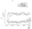
- Figure 6 shows the frequency characteristic of the gain and the ratio-to-axis of the embodiments of the 4-wire fractional-winding helical antenna of the present invention.
- Figure 7 shows a mask used for putting the method of the present invention into practice and the method for forming a conductor pattern with the mask.
- Figure 8 is a cross-section of a 4-wire fractional-winding helical antenna unit of the present invention.
- Figure 9 is a perspective view of the antenna unit shown in FIG 8.
- Figure 10 is the radiation pattern of the 4-wire fractional-winding helical antenna unit of the present invention.
- Figure 11 is a cross-section of a conventional 4-wire fractional-winding helical antenna unit.
- Figure 12 is a perspective view of a conventional 4-wire fractional-winding helical antenna.
- Figures 13 (a), (b) and (c) show dimensions of a conventional straight-cylinder 4-wire fractional-winding helical antenna and the SWRs measured at the two input-side terminals of a balun.
- Figure 14 is a cross-section of an example of a conventional 4-wire fractional-winding helical antenna unit.
- Figure 15 is the radiation pattern of the 4-wire fractional-winding helical antenna unit shown in Figure 14.
- Figure 1 is a perspective view of the first embodiment of the 4-wire fractional-winding helical antenna of the present invention.
- 4 conductors of a 4-wire fractional-winding helical antenna are formed around the surface of a mylar member 5 made by coaxially connecting a first cylindrical portion 2 with a tapered portion 1 formed by cutting the corner around the top end, a second cylindrical portion 3 of a greater diameter, and a second tapered portion 4 between the cylindrical portions 2 and 3.
- the supporting member has the two cylinder portions of different diameters connected coaxially in a stepped cylinder and has tapered portions at the top and between the two cylindrical portions.
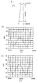
- Figures 2 (a), (b) and (c) show the dimensions and measured results of the first embodiment.
- the diameters of the upper and lower cylindrical portions 2 and 3 are 20 mm and 25 mm respectively and other dimensions are as shown in Figure (a).
- the conductor pattern is so formed that SWRs are equal to or smaller than 1.5 over the frequency bands of 1.53 to 1.56 GHz and 1.63 to 1.66 GHz.
- Figures 2 (b) and (c) show the frequency characteristic of the VSWRs measured at the two input terminals of the balun.
- the antenna shown in Figure 3 (a) has a comparatively short tapered portion formed only at the top end, which has the characteristics shown in Figures 3 (b) and (c).
- the characteristics are improved as compared with those of the conventional antenna, though the characteristic in Figure 3 (b) is slightly deteriorated at the upper limit frequency.
- the antenna shown in Figure 4 (a) has the same form as the above antenna with a tapered portion extended longer.
- This antenna has the characteristics shown in Figures 4 (b) and (c) similar to those in Figure 3.
- the antenna shown in Figure 5 (a) has a cylinder or cylindrical tube slightly tapered over the whole length.
- a general improvement is also noticeable in the characters of this form of antenna as shown in Figures (b) and (c), as compared with those of the conventional antenna.
- Figure 7 shows a mask used for putting the method of the present invention into practice and the method of forming the conductor pattern using the mask.
- the mask 64 shown is for forming the helical antenna pattern on the side surface of a Teflon stepped cylinder (antenna supporting member) 61 with cylindrical portions of different outer diameters.
- the mask 64 is in the form of a sheath 65 whose inner surface fits closely to the outer surface of the stepped cylindrical member 61.
- the sheath 65 is made of a transparent thin sheet such as resins.
- the larger-diameter bottom end of the sheath 65 is opened so that the mask can be fitted on the stepped cylindrical member 61 by simply putting the mask on the member 61 from the top end as shown in Figure 7.
- the sheath 65 has helical transparent parts 67 corresponding to the antenna pattern to be formed on the outer surface of the stepped cylinder 61 left in the opaque ground 66.
- transparent parts 67b are formed in the top end of the mask with one of them broken to form a gap to pass the other.
- the top end of the sheath 65 may be opened.
- the process of forming an antenna pattern using the above mask 64 is as follows.
- the surface of the Teflon stepped cylinder 61 is roughed with a chemical agent. This roughing of the surface of the member 61 is to increase the adhesion strength of a metal layer formed at the next step.
- a metal layer is formed uniformly on the surface of the member 61 by evaporation or electroless plating and a photoresist is applied to the metal layer in a darkroom. Then the mask 64 is fitted on the member 61.
- the photoresist While rotating the member 61 along with the mask 64, the photoresist is irradiated with the light to which it is sensitive. The photoresist under the transparent parts 67 is thereby exposed to the light and cures. The exposure may also be carried out without rotating the member 61 by irradiating light from all around the member 61.
- the mask 64 is removed from the member 61. Then unexposed photoresist is removed with a chemical agent such as hypo (sodium thiosulfate) and further the metal layer under the removed unexposed photoresist is removed by an etching agent.
- a chemical agent such as hypo (sodium thiosulfate) and further the metal layer under the removed unexposed photoresist is removed by an etching agent.
- This etching process thus can form the antenna pattern easily and very precisely on a stepped cylindrical member and hence makes a mass production with a reduced cost possible.
- this etching method using the above mask can be applied not only to a stepped cylinder but also to cylinder, cone, and other solid bodies.
- this etching process can be carried out easily by making a mask in the form of a sheath which fits closely to the outer surface of the supporting member.
- cylinder used in the claim is a concept including not only cylinder but also stepped cylinder, prism, cone, and other solid bodies.
- a preferable method for making the mask is cutting a resin sheet into the developed shape of the mask, making the ground 66 opaque leaving transparent parts 67 corresponding to the antenna pattern, and then forming the sheet into a sheath 65.
- the sheath may be further hot-molded using a mold in the same form as the supporting member 61 to make the sheath fit closely to the supporting member 61 as those with tapered portions.
- the 4-wire fractional-winding helical antenna of the first embodiment of the present invention has a usable broader frequency bands, it makes easy simultaneous transmission and reception through distant frequency bands with one antenna.
- the conductor pattern required for the above 4-wire fractional-winding helical antenna of the present invention can be formed easily and very precisely on the surface of cylinder, cylindrical tube, and particularly a stepped cylinder of gradually increased different diameters by the method of the present invention, the method is very effective for a mass production with a reduced cost of the 4-wire fractional-winding helical antenna of the present invention.
- Figure 8 shows a cross section of an antenna unit as the second embodiment of the present invention.
- Figure 9 is the perspective view of the antenna unit.
- This antenna unit is so constructed as to be fixed to the airframe 71 of an aircraft and comprises an aluminum base plate 72, a shield plate 74 supported on members 73 perpendicular to the base plate 72 spaced apart from the base plate 72, an antenna 75 mounted on the shield plate 74, and a hybrid circuit (HYB) 76 and a balun 77 disposed on the base plate 72 beneath the shield plate 74.
- HYB hybrid circuit
- the antenna body 75 comprises a mylar supporting member 80 and two antenna elements 81 and 82 in the form of narrow strips.
- the bottom ends of one antenna element are connected to the balun 77 through a semirigid cable 83 and those of the other antenna element are connected to the balun 77 through a semirigid cable 84.
- the antenna 75 comprises a supporting member 80 and two antenna elements 81 and 82 in the form of narrow strips wound helically around the supporting member 80.
- the bottom ends of these antenna elements 81 and 82 are connected to the balun 77 by means of semirigid cables 83 and 84.
- the antenna 75 may be the type as shown in Figure 1 and Figure 2 (a). It may also be the type as shown in Figure 3 (a), Figure 4 (a) or Figure 5 (a). It may even be the one with a straight cylinder shown in Figure 12 and Figure 13 (a).
- the shield plate 74 comprises an aluminum plate 85, for example, and a layer of an electromagnetic wave absorbing material 86 such as ferrite coated over the top face of the aluminum plate 85.
- the shield plate 74 is provided between the antenna 75 and the coupling and conversion circuits such as the hybrid circuit 76 and the balun 77, the electromagnetic wave radiated from the antenna 75 toward the base plate 72 and the airframe 71 in the vicinity of the antenna unit is absorbed by the layer 86 and consequently the bad influence of reflected wave on the directional pattern is significantly reduced.
- a conductive plate 85 such as aluminum provides the shielding effect of electric field between the antenna 75 and the coupling and conversion circuits such as the hybrid circuit 76 and the balun 77.
- Figure 10 shows the gain in the perpendicular direction of the radiation pattern of the 4-wire fractional-winding helical antenna unit of the present invention.
- the difference between the inner radiation pattern P1' which connects the minimum value of the gain in each direction and the outer radiation pattern P2' which connects the maximum value of the gain in each direction is smaller and the whole form of the radiation pattern is nearer to a circle compared with that in Figure 15. It is thus known that the radiation characteristics of the antenna unit is significantly improved.
- the balun 77 is a part for an unbalanced-balanced conversion between the hybrid circuit 76 and the antenna 75.
- the antenna unit of the second embodiment of the present invention has the shield plate 74 provided between the antenna 75 and the circuits 75 and 76, the electromagnetic wave radiated toward the antenna base and the airframe is absorbed by the shield plate 74 and the above problem is prevented.
- the second embodiment of the present invention can prevent the deterioration of the directional pattern caused by a part of the electromagnetic wave radiated from the antenna being reflected by the components at the antenna base and the airframe and the lowering of the antenna performance caused by the electromagnetic wave mixing with the signals in the circuits at the antenna base.
Landscapes
- Details Of Aerials (AREA)
- Support Of Aerials (AREA)
Abstract
Applications Claiming Priority (7)
| Application Number | Priority Date | Filing Date | Title |
|---|---|---|---|
| JP123190 | 1990-01-08 | ||
| JP1231/90 | 1990-01-08 | ||
| JP26333190 | 1990-10-01 | ||
| JP263331/90 | 1990-10-01 | ||
| JP319689/90 | 1990-11-21 | ||
| JP31968990 | 1990-11-21 | ||
| PCT/JP1990/001650 WO1991011038A1 (fr) | 1990-01-08 | 1990-12-18 | Antenne helicoidale a enroulement a nombre fractionnaire et a quatre fils |
Publications (3)
| Publication Number | Publication Date |
|---|---|
| EP0465658A1 true EP0465658A1 (fr) | 1992-01-15 |
| EP0465658A4 EP0465658A4 (en) | 1992-04-29 |
| EP0465658B1 EP0465658B1 (fr) | 1996-10-16 |
Family
ID=27274824
Family Applications (1)
| Application Number | Title | Priority Date | Filing Date |
|---|---|---|---|
| EP91900334A Expired - Lifetime EP0465658B1 (fr) | 1990-01-08 | 1990-12-18 | Antenne helicoidale a enroulement a nombre fractionnaire et a quatre fils |
Country Status (6)
| Country | Link |
|---|---|
| US (1) | US5353040A (fr) |
| EP (1) | EP0465658B1 (fr) |
| AU (1) | AU643244B2 (fr) |
| CA (1) | CA2047694C (fr) |
| DE (1) | DE69028919T2 (fr) |
| WO (1) | WO1991011038A1 (fr) |
Cited By (12)
| Publication number | Priority date | Publication date | Assignee | Title |
|---|---|---|---|---|
| WO1997001196A1 (fr) * | 1995-06-20 | 1997-01-09 | Saab Ericsson Space Ab | Element d'antenne conico-helicoidale produisant une polarisation pure sur une large plage de frequences |
| WO1998039816A1 (fr) * | 1997-03-03 | 1998-09-11 | Saab Ericsson Space Ab | Element d'antenne |
| US5859621A (en) * | 1996-02-23 | 1999-01-12 | Symmetricom, Inc. | Antenna |
| WO1999033146A1 (fr) * | 1997-12-19 | 1999-07-01 | Saab Ericsson Space Ab | Antenne helicoidale quadrifilaire a bifrequence |
| US5945963A (en) * | 1996-01-23 | 1999-08-31 | Symmetricom, Inc. | Dielectrically loaded antenna and a handheld radio communication unit including such an antenna |
| US6181297B1 (en) | 1994-08-25 | 2001-01-30 | Symmetricom, Inc. | Antenna |
| US6300917B1 (en) | 1999-05-27 | 2001-10-09 | Sarantel Limited | Antenna |
| EP0986132A3 (fr) * | 1998-09-07 | 2001-10-17 | Ace Technology | Antenne hélicoidale pour téléphones portables et méthode pour sa fabrication |
| US6369776B1 (en) | 1999-02-08 | 2002-04-09 | Sarantel Limited | Antenna |
| US6552693B1 (en) | 1998-12-29 | 2003-04-22 | Sarantel Limited | Antenna |
| US6690336B1 (en) | 1998-06-16 | 2004-02-10 | Symmetricom, Inc. | Antenna |
| WO2004089053A1 (fr) * | 2003-04-04 | 2004-10-14 | Per Jan Neergasrd | Procede pour eliminer le rayonnement emis par les telephones mobiles et autres appareils electriques ou electroniques |
Families Citing this family (19)
| Publication number | Priority date | Publication date | Assignee | Title |
|---|---|---|---|---|
| US5572172A (en) * | 1995-08-09 | 1996-11-05 | Qualcomm Incorporated | 180° power divider for a helix antenna |
| US5828348A (en) * | 1995-09-22 | 1998-10-27 | Qualcomm Incorporated | Dual-band octafilar helix antenna |
| US5955997A (en) * | 1996-05-03 | 1999-09-21 | Garmin Corporation | Microstrip-fed cylindrical slot antenna |
| US6088000A (en) * | 1999-03-05 | 2000-07-11 | Garmin Corporation | Quadrifilar tapered slot antenna |
| US6407709B1 (en) | 1999-07-16 | 2002-06-18 | Garmin Corporation | Mounting device with integrated antenna |
| KR20010058988A (ko) * | 1999-12-30 | 2001-07-06 | 구기덕 | 전자파 차단 기능을 가지는 안테나 및 그 제조 방법 |
| GB0027128D0 (en) * | 2000-11-04 | 2000-12-20 | Univ Bradford | Multi-band antenna |
| EP1346438A4 (fr) * | 2000-12-05 | 2004-09-01 | Chang Eung Soon | Dispositif destin a r duire l'onde lectromagn tique d'un terminal de communication mobile |
| RU2190941C1 (ru) * | 2001-01-09 | 2002-10-10 | Дочернее государственное унитарное предприятие "Научно-производственный центр спутниковых координатно-временных технологий "КОТЛИН" Федерального государственного унитарного предприятия "Российский институт радионавигации и времени" | Блок приемника сигналов спутниковых радионавигационных систем |
| FR2838524B1 (fr) * | 2002-04-15 | 2005-11-18 | Radiotelephone Sfr | Systeme et procede de localisation d'un terminal mobile, notamment pour le sauvetage d'une personne en detresse, et dispositif d'eveil d'un terminal mobile correspondant |
| US7038636B2 (en) * | 2003-06-18 | 2006-05-02 | Ems Technologies Cawada, Ltd. | Helical antenna |
| US7908080B2 (en) | 2004-12-31 | 2011-03-15 | Google Inc. | Transportation routing |
| DE112009005121B4 (de) * | 2009-08-06 | 2018-07-05 | Indian Space Research Organisation Of Isro | Gedruckte, quasi-konische Streifenwendel-Arrayantenne |
| US8994607B1 (en) * | 2011-05-10 | 2015-03-31 | The United States Of America As Represented By The Secretary Of The Navy | Spiral/conformal antenna using noise suppression/magnetic sheet above ground plane |
| US8552922B2 (en) * | 2011-11-02 | 2013-10-08 | The Boeing Company | Helix-spiral combination antenna |
| US9893715B2 (en) | 2013-12-09 | 2018-02-13 | Shure Acquisition Holdings, Inc. | Adaptive self-tunable antenna system and method |
| JP5922722B2 (ja) * | 2014-08-07 | 2016-05-24 | 日本電業工作株式会社 | アンテナ装置 |
| US11404771B2 (en) * | 2019-12-19 | 2022-08-02 | L3 Technologies, Inc. | Singular process printed antenna with feed network and systems and methods related to same |
| GB2630024A (en) * | 2023-05-10 | 2024-11-20 | Leonardo UK Ltd | An antenna |
Family Cites Families (12)
| Publication number | Priority date | Publication date | Assignee | Title |
|---|---|---|---|---|
| JPS41849B1 (fr) * | 1961-10-14 | 1966-01-27 | ||
| US3503075A (en) * | 1966-10-28 | 1970-03-24 | Research Corp | Helix antenna with polarization control |
| US3906509A (en) * | 1974-03-11 | 1975-09-16 | Raymond H Duhamel | Circularly polarized helix and spiral antennas |
| JPS5497353A (en) * | 1978-01-19 | 1979-08-01 | Mitsubishi Electric Corp | Conical and spiral antenna |
| US4169267A (en) * | 1978-06-19 | 1979-09-25 | The United States Of America As Represented By The Secretary Of The Air Force | Broadband helical antennas |
| JPS5799006A (en) * | 1980-12-12 | 1982-06-19 | Nec Corp | Helical antenna |
| US4506267A (en) * | 1983-01-26 | 1985-03-19 | Geophysical Survey Systems, Inc. | Frequency independent shielded loop antenna |
| US4635070A (en) * | 1983-12-19 | 1987-01-06 | Granger Associates | Dual mode antenna having simultaneous operating modes |
| US4675690A (en) * | 1984-05-25 | 1987-06-23 | Revlon, Inc. | Conical spiral antenna |
| US4697192A (en) * | 1985-04-16 | 1987-09-29 | Texas Instruments Incorporated | Two arm planar/conical/helix antenna |
| FR2624656B1 (fr) * | 1987-12-10 | 1990-05-18 | Centre Nat Etd Spatiales | Antenne de type helice et son procede de realisation |
| US5198831A (en) * | 1990-09-26 | 1993-03-30 | 501 Pronav International, Inc. | Personal positioning satellite navigator with printed quadrifilar helical antenna |
-
1990
- 1990-12-18 EP EP91900334A patent/EP0465658B1/fr not_active Expired - Lifetime
- 1990-12-18 CA CA002047694A patent/CA2047694C/fr not_active Expired - Fee Related
- 1990-12-18 WO PCT/JP1990/001650 patent/WO1991011038A1/fr not_active Ceased
- 1990-12-18 DE DE69028919T patent/DE69028919T2/de not_active Expired - Fee Related
- 1990-12-18 AU AU68945/91A patent/AU643244B2/en not_active Ceased
-
1993
- 1993-08-16 US US08/109,001 patent/US5353040A/en not_active Expired - Lifetime
Non-Patent Citations (1)
| Title |
|---|
| See references of WO9111038A1 * |
Cited By (15)
| Publication number | Priority date | Publication date | Assignee | Title |
|---|---|---|---|---|
| US6181297B1 (en) | 1994-08-25 | 2001-01-30 | Symmetricom, Inc. | Antenna |
| WO1997001196A1 (fr) * | 1995-06-20 | 1997-01-09 | Saab Ericsson Space Ab | Element d'antenne conico-helicoidale produisant une polarisation pure sur une large plage de frequences |
| US5929824A (en) * | 1995-06-20 | 1999-07-27 | Saab Ericsson Space Ab | Antenna element, conically helical, for polarization purity within a broad frequency range |
| US5945963A (en) * | 1996-01-23 | 1999-08-31 | Symmetricom, Inc. | Dielectrically loaded antenna and a handheld radio communication unit including such an antenna |
| US5859621A (en) * | 1996-02-23 | 1999-01-12 | Symmetricom, Inc. | Antenna |
| US6259420B1 (en) | 1997-03-03 | 2001-07-10 | Saab Ericsson Space Ab | Antenna element with helical radiation members |
| WO1998039816A1 (fr) * | 1997-03-03 | 1998-09-11 | Saab Ericsson Space Ab | Element d'antenne |
| WO1999033146A1 (fr) * | 1997-12-19 | 1999-07-01 | Saab Ericsson Space Ab | Antenne helicoidale quadrifilaire a bifrequence |
| US6421028B1 (en) | 1997-12-19 | 2002-07-16 | Saab Ericsson Space Ab | Dual frequency quadrifilar helix antenna |
| US6690336B1 (en) | 1998-06-16 | 2004-02-10 | Symmetricom, Inc. | Antenna |
| EP0986132A3 (fr) * | 1998-09-07 | 2001-10-17 | Ace Technology | Antenne hélicoidale pour téléphones portables et méthode pour sa fabrication |
| US6552693B1 (en) | 1998-12-29 | 2003-04-22 | Sarantel Limited | Antenna |
| US6369776B1 (en) | 1999-02-08 | 2002-04-09 | Sarantel Limited | Antenna |
| US6300917B1 (en) | 1999-05-27 | 2001-10-09 | Sarantel Limited | Antenna |
| WO2004089053A1 (fr) * | 2003-04-04 | 2004-10-14 | Per Jan Neergasrd | Procede pour eliminer le rayonnement emis par les telephones mobiles et autres appareils electriques ou electroniques |
Also Published As
| Publication number | Publication date |
|---|---|
| DE69028919D1 (de) | 1996-11-21 |
| EP0465658B1 (fr) | 1996-10-16 |
| CA2047694A1 (fr) | 1991-07-09 |
| AU643244B2 (en) | 1993-11-11 |
| US5353040A (en) | 1994-10-04 |
| AU6894591A (en) | 1991-08-05 |
| EP0465658A4 (en) | 1992-04-29 |
| CA2047694C (fr) | 1996-02-27 |
| WO1991011038A1 (fr) | 1991-07-25 |
| DE69028919T2 (de) | 1997-02-13 |
Similar Documents
| Publication | Publication Date | Title |
|---|---|---|
| EP0465658B1 (fr) | Antenne helicoidale a enroulement a nombre fractionnaire et a quatre fils | |
| Adams et al. | The quadrifilar helix antenna | |
| Kobayashi et al. | Dielectric tapered rod antennas for millimeter-wave applications | |
| US5861848A (en) | Circularly polarized wave patch antenna with wide shortcircuit portion | |
| US5134422A (en) | Helical type antenna and manufacturing method thereof | |
| US7489281B2 (en) | Quadrifilar helical antenna | |
| US4148030A (en) | Helical antennas | |
| US3906509A (en) | Circularly polarized helix and spiral antennas | |
| EP0969547B1 (fr) | Antenne | |
| US20210210865A1 (en) | Slotted substrate integrated air waveguide antenna array | |
| DE112009005121T5 (de) | Gedruckte, quasi-konische Streifenwendel-Arrayantenne | |
| US4260988A (en) | Stripline antenna for microwaves | |
| US4618865A (en) | Dielectric trough waveguide antenna | |
| JPS6367903A (ja) | アンテナ装置 | |
| Smith | The trap-loaded cylindrical antenna | |
| US11476587B2 (en) | Dielectric reflectarray antenna and method for making the same | |
| DE69208700T2 (de) | Gruppenantenne | |
| DE69801012T2 (de) | Kolineare Mikrostreifenleiterantenne | |
| GB2201046A (en) | Waveguide mode converter; antenna | |
| JP3212316B2 (ja) | 4線分数巻ヘリカルアンテナの製造方法 | |
| JP3301750B6 (ja) | 4線分数巻ヘリカルアンテナ | |
| JP3301750B2 (ja) | 4線分数巻ヘリカルアンテナ | |
| Ederra et al. | Sub-millimeter-wave imaging array at 500 GHz based on 3-D electromagnetic-bandgap material | |
| JPH03166802A (ja) | マイクロストリップアンテナ | |
| US5337060A (en) | Micro-strip antenna |
Legal Events
| Date | Code | Title | Description |
|---|---|---|---|
| PUAI | Public reference made under article 153(3) epc to a published international application that has entered the european phase |
Free format text: ORIGINAL CODE: 0009012 |
|
| 17P | Request for examination filed |
Effective date: 19911003 |
|
| AK | Designated contracting states |
Kind code of ref document: A1 Designated state(s): DE FR GB NL |
|
| A4 | Supplementary search report drawn up and despatched |
Effective date: 19920312 |
|
| AK | Designated contracting states |
Kind code of ref document: A4 Designated state(s): DE FR GB NL |
|
| 17Q | First examination report despatched |
Effective date: 19940425 |
|
| GRAG | Despatch of communication of intention to grant |
Free format text: ORIGINAL CODE: EPIDOS AGRA |
|
| GRAH | Despatch of communication of intention to grant a patent |
Free format text: ORIGINAL CODE: EPIDOS IGRA |
|
| GRAH | Despatch of communication of intention to grant a patent |
Free format text: ORIGINAL CODE: EPIDOS IGRA |
|
| GRAA | (expected) grant |
Free format text: ORIGINAL CODE: 0009210 |
|
| AK | Designated contracting states |
Kind code of ref document: B1 Designated state(s): DE FR GB NL |
|
| ET | Fr: translation filed | ||
| REF | Corresponds to: |
Ref document number: 69028919 Country of ref document: DE Date of ref document: 19961121 |
|
| PLBE | No opposition filed within time limit |
Free format text: ORIGINAL CODE: 0009261 |
|
| STAA | Information on the status of an ep patent application or granted ep patent |
Free format text: STATUS: NO OPPOSITION FILED WITHIN TIME LIMIT |
|
| 26N | No opposition filed | ||
| PGFP | Annual fee paid to national office [announced via postgrant information from national office to epo] |
Ref country code: GB Payment date: 20001213 Year of fee payment: 11 |
|
| PGFP | Annual fee paid to national office [announced via postgrant information from national office to epo] |
Ref country code: DE Payment date: 20001218 Year of fee payment: 11 |
|
| PGFP | Annual fee paid to national office [announced via postgrant information from national office to epo] |
Ref country code: NL Payment date: 20001231 Year of fee payment: 11 |
|
| PGFP | Annual fee paid to national office [announced via postgrant information from national office to epo] |
Ref country code: FR Payment date: 20011212 Year of fee payment: 12 |
|
| PG25 | Lapsed in a contracting state [announced via postgrant information from national office to epo] |
Ref country code: GB Free format text: LAPSE BECAUSE OF NON-PAYMENT OF DUE FEES Effective date: 20011218 |
|
| REG | Reference to a national code |
Ref country code: GB Ref legal event code: IF02 |
|
| PG25 | Lapsed in a contracting state [announced via postgrant information from national office to epo] |
Ref country code: NL Free format text: LAPSE BECAUSE OF NON-PAYMENT OF DUE FEES Effective date: 20020701 |
|
| PG25 | Lapsed in a contracting state [announced via postgrant information from national office to epo] |
Ref country code: DE Free format text: LAPSE BECAUSE OF NON-PAYMENT OF DUE FEES Effective date: 20020702 |
|
| GBPC | Gb: european patent ceased through non-payment of renewal fee |
Effective date: 20011218 |
|
| NLV4 | Nl: lapsed or anulled due to non-payment of the annual fee |
Effective date: 20020701 |
|
| PG25 | Lapsed in a contracting state [announced via postgrant information from national office to epo] |
Ref country code: FR Free format text: LAPSE BECAUSE OF NON-PAYMENT OF DUE FEES Effective date: 20030901 |
|
| REG | Reference to a national code |
Ref country code: FR Ref legal event code: ST |