EP0465711B1 - Verfahren und Vorrichtung zur Abtrennung eines Stoffes von einer Unterlage - Google Patents
Verfahren und Vorrichtung zur Abtrennung eines Stoffes von einer Unterlage Download PDFInfo
- Publication number
- EP0465711B1 EP0465711B1 EP90113356A EP90113356A EP0465711B1 EP 0465711 B1 EP0465711 B1 EP 0465711B1 EP 90113356 A EP90113356 A EP 90113356A EP 90113356 A EP90113356 A EP 90113356A EP 0465711 B1 EP0465711 B1 EP 0465711B1
- Authority
- EP
- European Patent Office
- Prior art keywords
- filter
- belt
- filter belt
- substance
- band
- Prior art date
- Legal status (The legal status is an assumption and is not a legal conclusion. Google has not performed a legal analysis and makes no representation as to the accuracy of the status listed.)
- Expired - Lifetime
Links
- 239000000126 substance Substances 0.000 title claims abstract description 16
- 238000000034 method Methods 0.000 title abstract description 5
- 238000000926 separation method Methods 0.000 title abstract description 5
- 229910000831 Steel Inorganic materials 0.000 claims description 4
- 239000010959 steel Substances 0.000 claims description 4
- 210000001520 comb Anatomy 0.000 claims description 3
- 239000000463 material Substances 0.000 abstract description 10
- 239000002244 precipitate Substances 0.000 abstract description 7
- 239000002699 waste material Substances 0.000 abstract 1
- 239000003795 chemical substances by application Substances 0.000 description 7
- 239000012065 filter cake Substances 0.000 description 6
- 238000001556 precipitation Methods 0.000 description 6
- 239000000839 emulsion Substances 0.000 description 5
- 239000004744 fabric Substances 0.000 description 4
- 239000010842 industrial wastewater Substances 0.000 description 2
- 239000000047 product Substances 0.000 description 2
- 239000013049 sediment Substances 0.000 description 2
- XLYOFNOQVPJJNP-UHFFFAOYSA-N water Substances O XLYOFNOQVPJJNP-UHFFFAOYSA-N 0.000 description 2
- 229920002678 cellulose Polymers 0.000 description 1
- 239000001913 cellulose Substances 0.000 description 1
- 230000007613 environmental effect Effects 0.000 description 1
- 239000000835 fiber Substances 0.000 description 1
- 239000000706 filtrate Substances 0.000 description 1
- 238000001914 filtration Methods 0.000 description 1
- 238000010169 landfilling Methods 0.000 description 1
- 239000007788 liquid Substances 0.000 description 1
- 239000000203 mixture Substances 0.000 description 1
- 229910021647 smectite Inorganic materials 0.000 description 1
- 239000000243 solution Substances 0.000 description 1
- 239000002594 sorbent Substances 0.000 description 1
- 239000000758 substrate Substances 0.000 description 1
- 239000002351 wastewater Substances 0.000 description 1
- 238000004065 wastewater treatment Methods 0.000 description 1
Images
Classifications
-
- B—PERFORMING OPERATIONS; TRANSPORTING
- B01—PHYSICAL OR CHEMICAL PROCESSES OR APPARATUS IN GENERAL
- B01D—SEPARATION
- B01D33/00—Filters with filtering elements which move during the filtering operation
- B01D33/04—Filters with filtering elements which move during the filtering operation with filtering bands or the like supported on cylinders which are impervious for filtering
-
- B—PERFORMING OPERATIONS; TRANSPORTING
- B01—PHYSICAL OR CHEMICAL PROCESSES OR APPARATUS IN GENERAL
- B01D—SEPARATION
- B01D33/00—Filters with filtering elements which move during the filtering operation
- B01D33/44—Regenerating the filter material in the filter
- B01D33/46—Regenerating the filter material in the filter by scrapers, brushes nozzles or the like acting on the cake-side of the filtering element
- B01D33/466—Regenerating the filter material in the filter by scrapers, brushes nozzles or the like acting on the cake-side of the filtering element scrapers
Definitions
- the invention relates to a device for separating a substance from a base, in particular the separation of a pulpy, precipitated substance from a filter belt.
- the precipitate or sediment is held back by a filter belt while the water flows through and collects with a filtrate container.
- the filter belt with the precipitate thereon which forms a more or less continuously determined thickness, is discarded together with this precipitate, ie the filter belt with the precipitate thereon is deposited on one because the precipitate can be an environmentally unfriendly substance Special landfill deposited.
- the object of the present invention is therefore to remove the environmentally unfriendly substance from the base z. B. to separate from the filter belt and deposit underlay and fabric separately according to their environmental sustainability.
- the release agent for separating the material from the base is a thin steel wire and its distance from the surface of a surface-polished rod is slightly more than the base is thick.
- the wire separates the fabric lying on the surface in piles or piles like a knife. It falls into a receptacle while the liberated, continuously moving, tensioned pad is collected elsewhere.
- the base is a filter belt and the material on top is a sediment from wastewater treatment or from a broken emulsion.
- a device for a mechanical filter on the surface of which a filter cake builds up, which is repelled by counter pressure at the end of the filtering process and the removal of the filter cake by two parallel and spaced apart Tensioned wires are supported, one of which is a thin piano wire and the second of a thicker rod-shaped material.
- the thin piano string wire conveys together with the counter pressure the separation of the cake from the filter medium, which connects again somewhat with the filter medium and is then raised by the thicker rod. It is not necessary here to keep a filter medium, for example a filter belt, taut.
- a tensioned wire-like body is provided, which is perpendicular to the path of movement of a filter, for example a drum filter, and is vibrated so that the wire moves towards and away from the filter cake.
- the filter cake should either be separated from the filter medium or compacted so that it as a whole separates from the filter medium.
- a device for tensioning a loosely falling filter medium with a filter cake adhering to it is not necessary.
- the present invention is therefore based on the object of pulling a loosely falling filter medium in the form of a band and keeping it taut, so that a filter cake located thereon can be separated.
- This object is achieved in that a roller rotating under the filter belt pulls the filter belt between a rod and a release agent.
- the roller has a speed that is greater than the feed speed of the filter belt, and is on its surface with in the axial direction provided elevations that can take the form of ribs, combs or brushes.
- the filter belt then contains practically no more harmful substance to be deposited separately because it has better cohesion than the filter belt with different materials, so it easily detaches.
- the material to be separated can lie on the filter belt more or less distributed in loose piles. It can also be pre-dewatered by press rolls, so that it forms patties which can be separated from the base more easily by the pressing process.
- a roller with ribs, combs, brushes or the like extending in the axial direction on the surface of the roller serves to hold the filter belt taut, the roller running faster than the transport speed of the support.
- the device for processing used emulsions pp. is described and there an essential Field of application, it is nevertheless also suitable for separating substances from documents that have nothing to do with the treatment of industrial waste water or emulsions, but where it is desirable to separate a substance from a continuously moving substrate, e.g. from conveyor belts for mushy or smectite fabrics.
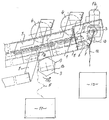
- the part of a cantilever of a device for treating waste water leading from left to right which is shown in the drawing, consists of steel profiles 1, which are connected to one another, and bearing and guiding devices for the belt filter.
- the belt filter consists of an endless, driven cell belt or link belt, on which the filter belt rests and is carried by it.
- This band filter is indicated by the double dashed line 2, runs in guides within this extension arm, is endless and is driven by a gear-like roller 3, which can be set in selectable revolutions by a geared motor 14.
- the filter belt On the surface of the upper run 2 'is the filter belt, which is a thin, band-shaped fleece of a certain width. Above this filter belt 5 on the upper run 2 'of the cell belt press rolls 4 are arranged, which compress the precipitation or the material not visible in the drawing on the filter belt 5 and free it from water.
- the filter belt separates from the cell belt on the roller 3 and is now, as the dash-dotted line 5, which is to represent the filter belt, passed between a rod 6 arranged in the frame 1 and a wire 7 serving as a separating agent. The distance between the wire 7 and the rod 6, over the surface of which the filter belt 5 slides, is only slightly larger than the filter belt is thick.
- the filter belt is then guided further over a driven roller 8 which, as in the exemplary embodiment shown, is polygonal and therefore has rib-like elevations 9 which extend in the axial direction over the entire length of the roller.
- the direction of rotation of this roller 8 takes place in the direction of arrow 10 at a speed which is greater than the feed or conveying speed of the belt filter and thus of the filter belt 5.
- the filter belt 5 Due to the rapid rotation of the roller 8 in the direction of arrow 10, the filter belt 5 is always kept taut after leaving the link belt 2 and pulled through the gap between the rod 6 and the release agent or wire 7. Due to this pulling movement, material, precipitation or the like, which is designated by the reference symbol 12, lying on the surface of the filter belt 5 is virtually cut off from the surface of the filter belt 5 and the filter belt 5 continues to run without the substance 12 lying thereon. The substance 12, precipitate or the like, is collected in the container 13.
Landscapes
- Chemical & Material Sciences (AREA)
- Chemical Kinetics & Catalysis (AREA)
- Filtration Of Liquid (AREA)
- Processing Of Solid Wastes (AREA)
- Organic Low-Molecular-Weight Compounds And Preparation Thereof (AREA)
- Control And Other Processes For Unpacking Of Materials (AREA)
- Treatment Of Liquids With Adsorbents In General (AREA)
Description
- Die Erfindung betrifft eine Vorrichtung zur Abtrennung eines Stoffes von einer Unterlage insbesondere die Abtrennung eines breiigen, ausgefällten Stoffes von einem Filterband.
- Aus der europäischen Patentschrift 0 067 959 ist eine Vorrichtung zur Aufbereitung von verbrauchten Emulsionen, Lösungen, Industrieabwässern und dergleichen beschrieben, in der die Flüssigkeit mit einem Gemisch chemischer Stoffe behandelt wird durch den z. B. eine Emulsion gebrochen und ausgepflockt wird, dabei von einem Sorptionsmittel sorbiert und auf ein Bandfilter sedimeniert wird, Der Bandfilter besteht aus einem endlosen, mitlaufenden Zellenband und einem darauf liegenden Filterband, beispielsweise aus einem Vlies.
- Der Niederschlag oder das Sediment wird von einem Filterband zurückgehalten, während das Wasser hindurchfließt und sich mit einem Filtratbehälter sammelt. Das Filterband mit dem darauf liegenden Niederschlag, der eine mehr oder weniger kontinuierlich bestimmter Dicke bildet, wird mit diesem Niederschlag zusammen verworfen, d. h. das Filterband mit dem darauf befindlichen Niederschlag wird, weil es sich bei dem Niederschlag um einen umweltunfreundlichen Stoff handeln kann, auf einer Spezialdeponie deponiert.
- Das, was also deponiert wird, ist ein Produkt umweltfreundlicher Art, nämlich das Filterband aus Zellulose- oder Kunststoffasern und einem umweltunfreundlichen Produkt, nämlich dem Niederschlag. Würde man den wirklich umweltunfreundlichen, also schädlichen Niederschlag getrennt auffangen und deponieren können, würde die Masse an Deponat beträchtlich verringert und damit die Kapazität der Deponie erweitert werden.
- Aufgabe der vorliegenden Erfindung ist es daher, den umweltunfreundlichen Stoff von der Unterlage z. B. von dem Filterband zu trennen und Unterlage und Stoff getrennt entsprechend ihrer Umweltverträglichkeit zu deponieren.
- Gelöst wird dieses Problem durch eine Stange mit einem in geringem Abstand darüber gespannten Trennmittel, zwischen denen das Filterband hindurchgeführt und gespannt gehalten wird, in dem die Spannung im Filterband durch eine unter dem Filterband und im Abstand zu dem Trennmittel rotierende Walze erzeugt ist, deren Oberfläche mit in axialer Richtung verlaufenden Erhebungen versehen ist.
- Das Trennmittel zur Abtrennung des Stoffes von der Unterlage ist im einfachsten Falle ein dünner Stahldraht und sein Abstand zur Oberfläche einer oberflächlich polierten Stange beträgt etwas mehr als die Unterlage dick ist.
- Wird nun die mit dem Stoff beladene Unterlage zwischen Draht und Stange hindurchgezogen, so trennt der Draht wie ein Messer den fladen- oder haufenweise auf der Unterlage liegenden Stoff von dieser ab. Er fällt in einen Aufnahmebehälter, während die von Stoff befreite, sich kontinuierlich bewegende, unter Spannung gehaltende Unterlage an einem anderen Ort aufgefangen wird.
- Bezogen auf das eben genannte europäische Patent, welches zum Stand der Technik gehört, ist die Unterlage ein Filterband und der daraufliegende Stoff ein Sediment aus der Abwasserreinigung oder von einer gebrochenen Emulsion.
- Es ist leicht einzusehen, daß ein derartiges Verfahren und eine derartige Vorrichtung erhebliche Mengen völlig harmloser Stoffe von jenen Stoffen trennen, die eine weitere sorgfältige Deponierung in einer speziellen Deponie erfordern.
- Aus der US-A-2 395 499 ist eine Vorrichtung für einen mechanischen Filter bekannt, auf dessen Oberfläche sich ein Filterkuchen aufbaut, der am Ende des Filtervorganges durch Gegendruck abgestoßen wird und wobei die Entfernung des Filterkuchens durch zwei parallel zueinander und im Abstand zueinander verlaufende gespannte Drähte unterstützt wird, von denen der eine ein dünner Klaviersaitendraht ist und der zweite aus einem dickeren stabförmigen Material besteht. Der dünne Klaviersaitendraht befördert zusammen mit dem Gegendruck die Trennung des Kuchens von dem Filtermedium, welcher sich aber wieder etwas mit dem Filtermedium verbindet und anschließend von dem dickeren Stab angehoben wird. Ein Gespannthalten eines Filtermediums, beispielsweise eines Filterbandes, ist hier nicht erforderlich.
- In der US-A-3 545 924 ist ein gespannter drahtartiger Körper vorgesehen, der rechtwinklig zum Bewegungsweg eines Filters, beispielsweise eines Trommelfilters, verläuft und in Schwingungen versetzt wird, so daß der Draht Bewegung auf den Filterkuchen zu und von diesem weg ausführt.
- Auf diese Weise soll der Filterkuchen entweder von dem Filtermedium abgetrennt oder kompaktiert werden, so daß er sich als ganzes von dem Filtermedium abtrennt. Auch hier ist also eine Vorrichtung zum Spannen eines locker fallenden Filtermediums mit einem darauf haftenden Filterkuchen nicht erforderlich.
- Der vorliegenden Erfindung liegt daher die Aufgabe zugrunde, ein locker fallendes Filtermedium in Form eines Bandes zu ziehen und dabei gespannt zu halten, so daß ein darauf befindlicher Filterkuchen abtrennbar ist.
- Gelöst wird diese Aufgabe dadurch, daß eine unter dem Filterband rotierende Walze das Filterband zwischen einer Stange und einem Trennmittel hindurchzieht.
- Die Walze weist eine Geschwindigkeit auf, die größer ist als die Vorschubgeschwindigkeit des Filterbandes, und ist auf ihrer Oberfläche mit in axialer Richtung verlaufenden Erhebungen vesehen, die die Form von Rippen, Kämmen oder Bürsten haben können.
- Das Filterband enthält danach praktisch keinen schädlichen getrennt zu deponierenden Stoff mehr, weil dieser in sich eine bessere Kohäsion aufweist als zu dem stofflich unterschiedlichen Filterband, sich also leicht ablöst. Der abzutrennende Stoff kann in lockeren Haufen mehr oder weniger verteilt auf dem Filterband aufliegen. Er kann auch durch Preßwalzen vorentwässert sein, so daß er Fladen bildet, die durch den Preßvorgang noch leichter von der Unterlage abtrennbar sind.
- Zum Gespannthalten des Filterbandes dient eine Walze mit sich in axialer Richtung auf der Oberfläche der Walze erstreckenden Rippen-, Kamm-, Bürsten- oder dergleichen Erhebungen, wobei die Walze schneller läuft als die Transportgeschwindigkeit der Unterlage.
- Dadurch, daß diese rippen-, kamm- oder bürstenförmigen Erhebungen auf der Walze, gegen die vom Stoff befreite Oberfläche in Transportrichtung der Unterlage einwirken, wird die Unterlage laufend gespannt gehalten und zwischen der Stange und dem beispielsweise aus einem Draht bestehenden Trennmittel hindurchgezogen.
- Wenngleich die Vorrichtung zur Aufbereitung von verbrauchten Emulsionen pp. beschrieben ist und dort ein wesentliches Anwendungsgebiet besitzt, so ist sie dennoch auch zur Abtrennung von Stoffen von Unterlagen geeignet, die mit der Aufbereitung von Industrieabwässern oder Emulsionen nichts zu tun haben, aber wo es wünschenswert ist, von einer sich kontinuierlich bewegenden Unterlage einen darauf befindlichen Stoff abzutrennen, beispielsweise von Förderbändern für breiige oder smektitische Stoffe.
- Die Erfindung wird nun anhand einer Zeichnung, die einen Teil einer Bandfilteranlage zeigt, nämlich das Ende des Bandfilters, d. h. jenes Teils, wo sich das Filterband von einem endlosen, umlaufenden Zellenband trennt, näher ererläutert.
- In der einzigen Figur der Zeichnung ist ein Schnitt durch einen solchen Bandfilter gezeigt.
- Der in der Zeichnung dargestellte Teil eines von links nach rechts schräg nach oben führenden Auslegers einer Vorrichtung zur Aufbereitung von Abwässern besteht aus Stahlprofilen 1, die miteinander verbunden sind, und Lager- und Führungseinrichtungen für den Bandfilter tragen. Der Bandfilter besteht aus einem endlosen angetriebenen Zellenband oder Gliederband, auf welchem das Filterband aufliegt und von diesem mitgenommen wird.
- Dieser Bandfilter ist durch die doppelt gestrichelte Linie 2 angedeutet, läuft in Führungen innerhalb dieses Ausvlegers, ist endlos und wird von einer zahnradartigen Walze 3, die von einem Getriebemotor 14 in wählbare Umdrehungen versetzt werden kann, angetrieben.
- Auf der Oberfläche des oberen Trums 2' liegt das Filterband, welches ein dünnes, bandförmiges Vlies von bestimmter Breite ist. Oberhalb dieses Filterbandes 5 auf dem oberen Trum 2' des Zellenbandes sind Preßwalzen 4 angeordnet, die den in der Zeichnung nicht sichtbaren Niederschlag oder den nicht sichtbaren Stoff auf dem Filterband 5 verdichten und von Wasser befreien. Das Filterband trennt sich von dem Zellenband auf der Walze 3 und wird nun, wie die strichpunktierte Linie 5 zeigt, die das Filterband darstellen soll, zwischen einem fest im Gestell 1 angeordneten Stab 6 und einem als Trennmittel dienenden Draht 7 hindurchführt. Der Abstand zwischen dem Draht 7 und dem Stab 6, über dessen Oberfläche das Filterband 5 gleitet, ist nur etwas größer als das Filterband dick ist.
- Das Filterband ist dann weiter über eine angetriebene Walze 8 geführt, die wie im dargestellten Ausführungsbeispiel polygonal ist und deshalb rippenartige in axialer Richtung sich über die gesamte Länge der Walze erstreckende Erhebungen 9 aufweist. Die Rotationsrichtung dieser Walze 8 erfolgt in Richtung des Pfeiles 10 mit einer Geschwindigkeit, die größer ist als die Vorschub- oder Fördergeschwindigkeit des Bandfilters und damit des Filterbandes 5. Nachdem das Filterband 5 die Walze 8 verlassen hat, fällt es in einen Aufnahmebehälter 11.
- Durch die schnelle Umdrehung der Walze 8 in Richtung des Pfeiles 10 wird das Filterband 5 nach Verlassen des Gliederbandes 2 immer gestrafft gehalten und durch den Spalt zwischen Stab 6 und Trennmittel bzw. Draht 7 hindurchgezogen. Aufgrund dieser Zugbewegung wird auf der Oberfläche des Filterbandes 5 liegender Stoff, Niederschlag oder dergleichen, der mit dem Bezugszeichen 12 bezeichnet ist, von der Oberfläche des Filterbandes 5 geradezu abgeschnitten und das Filterband 5 läuft ohne den daraufliegenden Stoff 12 weiter. Der Stoff 12, Niederschlag oder dergleichen, wird in dem Behälter 13 gesammelt.
- Aus der obigen Beschreibung geht klar hervor, daß hier eine Trennung zwischen dem Filterband 5 und dem darauf befindlichen Stoff, Niederschlag oder dergleichen, vorgenommen wird und daß nur der Stoff, Niederschlag oder dergleichen, der umweltunfreundlich oder umweltschädlich ist, einer besonderen Spezialdeponie zugeführt werden muß, während das Filterband 5 auf einer ganz normalen, beispielsweise Hausmülldeponie, entsorgt werden kann.
Claims (3)
- Vorrichtung zur Abtrennung eines Stoffes von einem Filterband vermittels einem Stab (6) mit einem im geringen Abstand darüber gespannten Trennmittel (7), zwischen denen das Filterband (5) hindurchgezogen und gespannt gehalten wird, in dem die Spannung im Filterband (5) durch eine unter dem Filterband und im Abstand zu dem Trennmittel (7) in Transportrichtung des Filterbandes rotierende Walze (8) erzeugt ist, die eine Geschwindigkeit aufweist, die größer ist als die Vorschubgeschwindigkeit des Filterbandes, und deren Oberfläche mit in axialer Richtung verlaufenden Erhebungen (9) versehen ist.
- Vorrichtung nach Anspruch 1, dadurch gekennzeichnet, daß die Erhebungen (9) Rippen, Kämme oder Bürsten sind.
- Vorrichtung nach Anspruch 1, dadurch gekennzeichnet, daß das Trennmittel (7) ein dünner Stahldraht oder ein Stahlband ist.
Priority Applications (6)
| Application Number | Priority Date | Filing Date | Title |
|---|---|---|---|
| DE59006071T DE59006071D1 (de) | 1990-07-12 | 1990-07-12 | Verfahren und Vorrichtung zur Abtrennung eines Stoffes von einer Unterlage. |
| EP90113356A EP0465711B1 (de) | 1990-07-12 | 1990-07-12 | Verfahren und Vorrichtung zur Abtrennung eines Stoffes von einer Unterlage |
| AT90113356T ATE106766T1 (de) | 1990-07-12 | 1990-07-12 | Verfahren und vorrichtung zur abtrennung eines stoffes von einer unterlage. |
| ES90113356T ES2054168T3 (es) | 1990-07-12 | 1990-07-12 | Procedimiento y dispositivo para la separacion de una sustancia de una base. |
| DK90113356.1T DK0465711T3 (da) | 1990-07-12 | 1990-07-12 | Fremgangsmåde og indretning til separering af et stof fra et underlag |
| GR940300013T GR940300013T1 (en) | 1990-07-12 | 1994-03-31 | Process and device for the separation of a substance from a support. |
Applications Claiming Priority (1)
| Application Number | Priority Date | Filing Date | Title |
|---|---|---|---|
| EP90113356A EP0465711B1 (de) | 1990-07-12 | 1990-07-12 | Verfahren und Vorrichtung zur Abtrennung eines Stoffes von einer Unterlage |
Publications (2)
| Publication Number | Publication Date |
|---|---|
| EP0465711A1 EP0465711A1 (de) | 1992-01-15 |
| EP0465711B1 true EP0465711B1 (de) | 1994-06-08 |
Family
ID=8204212
Family Applications (1)
| Application Number | Title | Priority Date | Filing Date |
|---|---|---|---|
| EP90113356A Expired - Lifetime EP0465711B1 (de) | 1990-07-12 | 1990-07-12 | Verfahren und Vorrichtung zur Abtrennung eines Stoffes von einer Unterlage |
Country Status (6)
| Country | Link |
|---|---|
| EP (1) | EP0465711B1 (de) |
| AT (1) | ATE106766T1 (de) |
| DE (1) | DE59006071D1 (de) |
| DK (1) | DK0465711T3 (de) |
| ES (1) | ES2054168T3 (de) |
| GR (1) | GR940300013T1 (de) |
Family Cites Families (3)
| Publication number | Priority date | Publication date | Assignee | Title |
|---|---|---|---|---|
| FR656310A (fr) * | 1927-06-20 | 1929-05-06 | Anode Rubber Co England Ltd | Procédé et dispositif de filtrage de liquides tendant à se coaguler |
| US2395499A (en) * | 1943-10-08 | 1946-02-26 | Oliver United Filters Inc | Continuous filter |
| US3945924A (en) * | 1971-02-24 | 1976-03-23 | Peterson Filters & Engineering Company | Apparatus for impact discharge of filter cake from a moving filter medium and for compacting filter cake thereon |
-
1990
- 1990-07-12 DE DE59006071T patent/DE59006071D1/de not_active Expired - Fee Related
- 1990-07-12 AT AT90113356T patent/ATE106766T1/de not_active IP Right Cessation
- 1990-07-12 EP EP90113356A patent/EP0465711B1/de not_active Expired - Lifetime
- 1990-07-12 ES ES90113356T patent/ES2054168T3/es not_active Expired - Lifetime
- 1990-07-12 DK DK90113356.1T patent/DK0465711T3/da active
-
1994
- 1994-03-31 GR GR940300013T patent/GR940300013T1/el unknown
Also Published As
| Publication number | Publication date |
|---|---|
| EP0465711A1 (de) | 1992-01-15 |
| GR940300013T1 (en) | 1994-03-31 |
| DE59006071D1 (de) | 1994-07-14 |
| DK0465711T3 (da) | 1994-07-11 |
| ATE106766T1 (de) | 1994-06-15 |
| ES2054168T3 (es) | 1994-08-01 |
Similar Documents
| Publication | Publication Date | Title |
|---|---|---|
| AT390812B (de) | Waschvorrichtung fuer faserstoffsuspensionen | |
| DE1916701A1 (de) | Verfahren und Vorrichtung zum Entwaessern von Abwasserschlamm o.dgl. | |
| DE69813518T2 (de) | Vorrichtung zur herstellung von fasern | |
| EP0898012A1 (de) | Verfahren und Vorrichtung zum Auflösen von Faserstoffen | |
| DE2750191B2 (de) | Vorrichtung zur Aufbereitung von Altpapier | |
| DE2355309A1 (de) | Vorrichtung zur entwaesserung waesseriger schlammbruehen | |
| DE7801619U1 (de) | Kardiermaschine | |
| DE2723014A1 (de) | Verfahren und vorrichtung zum entfernen abfiltrierbarer stoffe aus einer fluessigkeit | |
| DE2751084C2 (de) | Verfahren und Vorrichtung zum Aufbereiten von Altpapier | |
| DE2063345C3 (de) | Vorrichtung zum Filtern von Abwasser | |
| DE1179518B (de) | Walzenpresse zum Entwaessern von Klaerschlamm | |
| EP0465711A1 (de) | Verfahren und Vorrichtung zur Abtrennung eines Stoffes von einer Unterlage | |
| DE2624367A1 (de) | Verfahren zum ausscheiden von verunreinigungen an karden und vorrichtung zur durchfuehrung des verfahrens | |
| DE1510320A1 (de) | Reisswolf,insbesondere fuer die Textilindustrie | |
| DE4137608C2 (de) | Vorrichtung zur Filterung von mit magnetisierbaren und nicht magnetisierbaren Feststoffen beladenen Flüssigkeiten | |
| DE2008831A1 (de) | Drehfiltervorrichtung und Filter verfahren | |
| DE3115576A1 (de) | Vorrichtung an pressen zur entwaesserung von materialien | |
| DE3245232A1 (de) | Verfahren und vorrichtung zum entwaessern eines schlammes aus feinen teilchen | |
| AT403170B (de) | Vorrichtung zum teilen eines kardenvlieses in längsabschnitte | |
| DE4323386A1 (de) | Vorrichtung zur Behandlung von Werstoffgemischen | |
| EP1712301A2 (de) | Vorrichtung und Verfahren zur Aufbereitung von Elektronikschrott | |
| EP0519309A2 (de) | Pressvorrichtung zum Flüssigkeitsentzug aus einem Gut | |
| DE3729103C2 (de) | ||
| DE864434C (de) | Vorrichtung zum Trennen verspinnbarer Fasern vom Pflanzensaft und Saftgewinnungs- und Brechverfahren | |
| DE346747C (de) | Vorrichtung zum Zerkleinern von Tabak fuer die Herstellung von Einlagen fuer Zigarren, Zigarillos u. dgl. |
Legal Events
| Date | Code | Title | Description |
|---|---|---|---|
| PUAI | Public reference made under article 153(3) epc to a published international application that has entered the european phase |
Free format text: ORIGINAL CODE: 0009012 |
|
| AK | Designated contracting states |
Kind code of ref document: A1 Designated state(s): AT BE CH DE DK ES FR GB GR IT LI LU NL SE |
|
| 17P | Request for examination filed |
Effective date: 19920714 |
|
| 17Q | First examination report despatched |
Effective date: 19930104 |
|
| ITF | It: translation for a ep patent filed | ||
| GRAA | (expected) grant |
Free format text: ORIGINAL CODE: 0009210 |
|
| AK | Designated contracting states |
Kind code of ref document: B1 Designated state(s): AT BE CH DE DK ES FR GB GR IT LI LU NL SE |
|
| REF | Corresponds to: |
Ref document number: 106766 Country of ref document: AT Date of ref document: 19940615 Kind code of ref document: T |
|
| EL | Fr: translation of claims filed | ||
| ET | Fr: translation filed | ||
| REG | Reference to a national code |
Ref country code: DK Ref legal event code: T3 |
|
| REF | Corresponds to: |
Ref document number: 59006071 Country of ref document: DE Date of ref document: 19940714 |
|
| ITTA | It: last paid annual fee | ||
| PGFP | Annual fee paid to national office [announced via postgrant information from national office to epo] |
Ref country code: NL Payment date: 19940731 Year of fee payment: 5 |
|
| REG | Reference to a national code |
Ref country code: ES Ref legal event code: FG2A Ref document number: 2054168 Country of ref document: ES Kind code of ref document: T3 |
|
| GBT | Gb: translation of ep patent filed (gb section 77(6)(a)/1977) |
Effective date: 19940712 |
|
| REG | Reference to a national code |
Ref country code: GR Ref legal event code: FG4A Free format text: 3012138 |
|
| PGFP | Annual fee paid to national office [announced via postgrant information from national office to epo] |
Ref country code: LU Payment date: 19941101 Year of fee payment: 5 |
|
| PGFP | Annual fee paid to national office [announced via postgrant information from national office to epo] |
Ref country code: DE Payment date: 19941119 Year of fee payment: 5 |
|
| PGFP | Annual fee paid to national office [announced via postgrant information from national office to epo] |
Ref country code: GR Payment date: 19941125 Year of fee payment: 5 Ref country code: FR Payment date: 19941125 Year of fee payment: 5 Ref country code: DK Payment date: 19941125 Year of fee payment: 5 |
|
| PGFP | Annual fee paid to national office [announced via postgrant information from national office to epo] |
Ref country code: GB Payment date: 19941129 Year of fee payment: 5 Ref country code: CH Payment date: 19941129 Year of fee payment: 5 |
|
| PGFP | Annual fee paid to national office [announced via postgrant information from national office to epo] |
Ref country code: AT Payment date: 19941130 Year of fee payment: 5 |
|
| PGFP | Annual fee paid to national office [announced via postgrant information from national office to epo] |
Ref country code: SE Payment date: 19941207 Year of fee payment: 5 |
|
| PGFP | Annual fee paid to national office [announced via postgrant information from national office to epo] |
Ref country code: ES Payment date: 19941209 Year of fee payment: 5 |
|
| PGFP | Annual fee paid to national office [announced via postgrant information from national office to epo] |
Ref country code: BE Payment date: 19941222 Year of fee payment: 5 |
|
| EAL | Se: european patent in force in sweden |
Ref document number: 90113356.1 |
|
| PLBE | No opposition filed within time limit |
Free format text: ORIGINAL CODE: 0009261 |
|
| STAA | Information on the status of an ep patent application or granted ep patent |
Free format text: STATUS: NO OPPOSITION FILED WITHIN TIME LIMIT |
|
| 26N | No opposition filed | ||
| PG25 | Lapsed in a contracting state [announced via postgrant information from national office to epo] |
Ref country code: LU Free format text: LAPSE BECAUSE OF NON-PAYMENT OF DUE FEES Effective date: 19950712 Ref country code: GB Effective date: 19950712 Ref country code: DK Effective date: 19950712 Ref country code: AT Effective date: 19950712 |
|
| REG | Reference to a national code |
Ref country code: DK Ref legal event code: EBP |
|
| PG25 | Lapsed in a contracting state [announced via postgrant information from national office to epo] |
Ref country code: SE Effective date: 19950713 Ref country code: ES Free format text: LAPSE BECAUSE OF EXPIRATION OF PROTECTION Effective date: 19950713 |
|
| PG25 | Lapsed in a contracting state [announced via postgrant information from national office to epo] |
Ref country code: LI Effective date: 19950731 Ref country code: CH Effective date: 19950731 Ref country code: BE Effective date: 19950731 |
|
| BERE | Be: lapsed |
Owner name: RALF F. PIEPHO ABWASSERTECHNIK G.M.B.H. Effective date: 19950731 |
|
| PG25 | Lapsed in a contracting state [announced via postgrant information from national office to epo] |
Ref country code: GR Free format text: THE PATENT HAS BEEN ANNULLED BY A DECISION OF A NATIONAL AUTHORITY Effective date: 19960131 |
|
| PG25 | Lapsed in a contracting state [announced via postgrant information from national office to epo] |
Ref country code: NL Effective date: 19960201 |
|
| GBPC | Gb: european patent ceased through non-payment of renewal fee |
Effective date: 19950712 |
|
| REG | Reference to a national code |
Ref country code: CH Ref legal event code: PL |
|
| REG | Reference to a national code |
Ref country code: GR Ref legal event code: MM2A Free format text: 3012138 |
|
| NLV4 | Nl: lapsed or anulled due to non-payment of the annual fee |
Effective date: 19960201 |
|
| PG25 | Lapsed in a contracting state [announced via postgrant information from national office to epo] |
Ref country code: DE Effective date: 19960402 |
|
| EUG | Se: european patent has lapsed |
Ref document number: 90113356.1 |
|
| PG25 | Lapsed in a contracting state [announced via postgrant information from national office to epo] |
Ref country code: FR Effective date: 19960430 |
|
| REG | Reference to a national code |
Ref country code: FR Ref legal event code: ST |
|
| REG | Reference to a national code |
Ref country code: FR Ref legal event code: ST |
|
| REG | Reference to a national code |
Ref country code: FR Ref legal event code: ST |
|
| REG | Reference to a national code |
Ref country code: ES Ref legal event code: FD2A Effective date: 19990601 |
|
| PG25 | Lapsed in a contracting state [announced via postgrant information from national office to epo] |
Ref country code: IT Free format text: LAPSE BECAUSE OF NON-PAYMENT OF DUE FEES;WARNING: LAPSES OF ITALIAN PATENTS WITH EFFECTIVE DATE BEFORE 2007 MAY HAVE OCCURRED AT ANY TIME BEFORE 2007. THE CORRECT EFFECTIVE DATE MAY BE DIFFERENT FROM THE ONE RECORDED. Effective date: 20050712 |