EP0465737A1 - Elektronisches Gegenmassnahmensystem - Google Patents
Elektronisches Gegenmassnahmensystem Download PDFInfo
- Publication number
- EP0465737A1 EP0465737A1 EP90307493A EP90307493A EP0465737A1 EP 0465737 A1 EP0465737 A1 EP 0465737A1 EP 90307493 A EP90307493 A EP 90307493A EP 90307493 A EP90307493 A EP 90307493A EP 0465737 A1 EP0465737 A1 EP 0465737A1
- Authority
- EP
- European Patent Office
- Prior art keywords
- threat
- signal
- vehicle
- radar
- slave
- Prior art date
- Legal status (The legal status is an assumption and is not a legal conclusion. Google has not performed a legal analysis and makes no representation as to the accuracy of the status listed.)
- Granted
Links
- 238000001514 detection method Methods 0.000 claims abstract description 8
- 230000000873 masking effect Effects 0.000 claims abstract description 6
- 238000005259 measurement Methods 0.000 claims description 9
- 230000001934 delay Effects 0.000 claims description 8
- 230000005540 biological transmission Effects 0.000 claims description 4
- 238000012544 monitoring process Methods 0.000 claims 1
- 230000003111 delayed effect Effects 0.000 description 11
- 238000000034 method Methods 0.000 description 9
- XUIMIQQOPSSXEZ-UHFFFAOYSA-N Silicon Chemical compound [Si] XUIMIQQOPSSXEZ-UHFFFAOYSA-N 0.000 description 5
- 230000007123 defense Effects 0.000 description 5
- 238000012545 processing Methods 0.000 description 5
- 229910052710 silicon Inorganic materials 0.000 description 5
- 239000010703 silicon Substances 0.000 description 5
- 230000009471 action Effects 0.000 description 4
- 238000003491 array Methods 0.000 description 2
- 230000015572 biosynthetic process Effects 0.000 description 2
- 238000010586 diagram Methods 0.000 description 2
- 230000000694 effects Effects 0.000 description 2
- 238000011156 evaluation Methods 0.000 description 2
- 230000010363 phase shift Effects 0.000 description 2
- 230000008569 process Effects 0.000 description 2
- 241001501852 Diomedeidae Species 0.000 description 1
- 230000001427 coherent effect Effects 0.000 description 1
- 238000012937 correction Methods 0.000 description 1
- 230000001419 dependent effect Effects 0.000 description 1
- 238000013461 design Methods 0.000 description 1
- 239000002674 ointment Substances 0.000 description 1
- 230000001629 suppression Effects 0.000 description 1
Images


Classifications
-
- G—PHYSICS
- G01—MEASURING; TESTING
- G01S—RADIO DIRECTION-FINDING; RADIO NAVIGATION; DETERMINING DISTANCE OR VELOCITY BY USE OF RADIO WAVES; LOCATING OR PRESENCE-DETECTING BY USE OF THE REFLECTION OR RERADIATION OF RADIO WAVES; ANALOGOUS ARRANGEMENTS USING OTHER WAVES
- G01S7/00—Details of systems according to groups G01S13/00, G01S15/00, G01S17/00
- G01S7/02—Details of systems according to groups G01S13/00, G01S15/00, G01S17/00 of systems according to group G01S13/00
- G01S7/38—Jamming means, e.g. producing false echoes
-
- G—PHYSICS
- G01—MEASURING; TESTING
- G01S—RADIO DIRECTION-FINDING; RADIO NAVIGATION; DETERMINING DISTANCE OR VELOCITY BY USE OF RADIO WAVES; LOCATING OR PRESENCE-DETECTING BY USE OF THE REFLECTION OR RERADIATION OF RADIO WAVES; ANALOGOUS ARRANGEMENTS USING OTHER WAVES
- G01S7/00—Details of systems according to groups G01S13/00, G01S15/00, G01S17/00
- G01S7/003—Transmission of data between radar, sonar or lidar systems and remote stations
Definitions
- the new system uses a low cost expendable remote jammer which is deployed in such a way that it is between the target and the threat radars being jammed i.e. inboard.
- the jammer is electronically linked to the target vehicle by a low probability of detection secure data link.
- the jammer acts as a simple repeater except it adds a command specified delay so that the transmitted pulse exactly masks the target at the threat radar receiver.
- the jammer changes the transmitted frequency so that it exactly matches the doppler of the target return.
- the target can command the jammer to address up to say ten or more threat radars in a single threat band channel per jammer module and each cover pulse will match the target pulse with say 50 nanoseconds to spare and will match the doppler frequency to less than the doppler filter width in the threat radar or say less than ten cycles.
- the data link measures the distance between the jammer and the target.
- the data link also commands the delay and the doppler that the jammer must give each threat radar pulse.
- the master unit in the target measures the difference in the time of arrival of the pulse that arrives directly from the threat radar and the pulse that is relayed by the jammer.
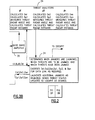
- the geometry of the situation and the formulas for calculating the delays and doppler shifts required by the jammer is given by Figure 1. The accuracy of these formulas and the ability of the master unit to measure these quantities accurately is an important part of this new system.
- This system is capable of providing protection to ships, aircraft, missiles, and space vehicles.
- the exact method of implementation depends on the vehicle protected and the operational scenario. However, in all these cases, we will have an off- board jammer (usually between the target and the threat radar) which we will call the slave, remote, or jammer unit and the equipment on the target vehicle, the master unit.
- an off- board jammer usually between the target and the threat radar
- FIG. 1 there is illustrated a schematic diagram of two threat radars 10 and 12, radar 10 operating at a frequency of f1 and radar 12 operating at a frequency of f2.
- both of these threat radars measure the delay time of the return signal from target 14 and the doppler shift in the signal.
- a slave jammer vehicle 16 containing slave jamming modules which send out a separate jamming signal for each threat radar.
- the distance from the radar 10 to the target 14 is shown as C1
- the distance from radar 10 to jammer 16 is A1
- the distance between jammer 16 and target 14 is B.
- the corresponding distances for the second threat radar 12 are A2, C2 and B and the Nth threat radar is An, Cn, and B..S.
- Each signal will have a subscript (eg 1,2,n) which identifies the particular threat radar for which the value is measured or calculated.
- the radar 10 Since the signal coming back from the jammer is coincident with that from the target in both time and frequency and at the wrong angle, the radar 10 measures a false angle to the target even though it has the correct range. Since the stronger signal is actually coming back to the wrong angle there is nothing that the radar can do to correct this error.
- n threat radars If there are n threat radars, n sets of measurements will be taken and Dsn and Dpn will be calculated and applied to the jamming signal.
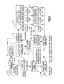
- Fig. 2 there is shown a schematic diagrammatic view of the electronic system on board the target 14 for making the measurements and calculations discussed above and communicating the appropriate commands to the slave (jammer) vehicle 16 (Fig. 1).
- the system comprises a receiving antenna 20 which has low directivity and covers all angles.
- a suitable antenna is any microwave antenna having an omnidirectional pattern and covering the threat radars' bandwidth. It may be necessary to use two or more antennas suitably combined to cover all angles and bandwidth.
- the signal received by antenna 20 is fed to a signal search, sort and threat identification system 22 which identifies the Threat Radar Signal, assigns a priority to the signal and transmit the signal to one of several threat analyzers 24.
- the operation of the low directivity Threat Radar Receiving Antenna and Signal Search, Sort, and Threat Evaluation is basically the state of the art as used by ASPJ and current Radar Warning and Homing Equipment.
- the operation of these circuits determines those threat radars that are currently threatening the target, their order of priority, and assigns a threat analyzer to each current threat.
- these circuits will monitor the effectiveness of the jamming, monitor for the appearance of new current threats, and reassigns threat analyzers as required.
- phased array transceiving antennas 26 arranged to receive threat signals from each threat radar and communicate with jammer 16. These phased arrays permit measurement of the angles ⁇ A, ⁇ A2, ⁇ An between the respective threat radars and the jammer vehicle 16.
- the received signals from antenna 26 are passed through a duplex switch 28 to a base band amplifier 30. From amplifier 30 the signals are fed to two correlators 32 and 36.
- Correlator 32 is a variable delay line correlator and doppler detector which measures delay Ddo and frequency shift Df. The measured values of Ddo and Df for each threat radar signal are then fed into the appropriate threat analyzer 24.
- the data link correlator 36 measures distance B and the doppler dB/dt.
- This correlator 36 also measures the angle ⁇ A to each jammer 16 from the target vehicle.
- the measured values of distance B and the doppler shift dB/df for each threat signal is also fed to the appropriate threat analyzer 24 which calculates Ds and Dp for each threat radar signal by using the equations:
- the action portion 34 of the data processing system determines when each jammer 16 is to be launched, which threats are to be jammed and which threats have been jammed. It also encodes Ds1, Ds2, Dsn (the delay for each threat radar signal) and Dp1, Dp2, Dpn (the doppler shift for each radar signal). These encoded signals are then fed back to a data link oscillator 38, the amplifier 40, the duplex switch 28 and to the antenna(s) for communicating with the appropriate jammer(s) 16.
- the action portion 34 also launches additional jammers as required and sends threat status updates to the cockpit.
- Fig. 3 there is shown a schematic diagram of a preferred slave electronic system for receiving and retransmitting radar signals from one or more threat radars under control of the encoded data transmitter from the master data processing system in the target 14.
- the slave (jammer) system includes an antenna 50 for receiving the various threat radar signals f1, f2, fn to be jammed. It also receives the data link signal from the master data processing system.
- the received signals are fed to a mixer 52 which also is fed by a local oscillator 53 which generates a separate frequency fa.
- the different signals f1-fa, f2-fa, fn-fa are fed from the mixer to a base band amplifier 54.
- the amplified signals are fed to a data link decoder 57 and a variable band width and gain amplifier 58.
- the Data link decoder sends appropriate band width and gain control signals from the master data processor to the variable band width and gain control circuit 58.
- the amplified signals from 58 are fed to the delay line 60.
- the Data link decoder also sends the values of the delay signals Ds1, Ds2, and Dsn to the delay line 60 which sets the position of the delay taps.
- the delay line 60 will produce a number of signals corresponding to the number of threat radar signals received.
- the output from the delay line will thus be:
- the data link decoder 57 also sends the decoded values of Dp1, Dp2, and Dpn to a doppler frequency synthesizer 59 which generates the appropriate frequencies of Dp1,Dp2, and Dpn which are fed (along with the outputs of the delay line 60) to a phase shift doppler generator 62 whose output signals are:
- These signals are fed to a threat band amplifier 69 and then to the transmitting antenna 80 where the target echo is returned to each threat radar the target echo having been delayed by the calculated Ds and having been given the appropriate Dp to mask the real target and given each threat radar a false target.
- While the threat analyzers 24 of Fig. 2 are shown as a separate block, they actually will only be a module of a software program.
- a threat analyzer When a threat analyzer has been assigned to a threat radar, it will first measure Ddo, Df, and the angle of arrival of the signal. It will then calculate the distance to the threat which will greatly help to evaluate the urgency of the threat. If any of the threats are immediate it will automatically launch the jammer or jammers required. It then calculates Ds and Dp required for the jammer to generate a masking pulse for the target and transmits these values to the jammer by means of the data link. When the jammer starts jamming the threat radar, the values of Ds and Dp as delays and doppler shifts, are introduced into the jammer. The threat analyzer checks to see if they are proper to generate the correct masking pulse and, if incorrect, sends correction commands to the jammer.
- the threat analyzer will continuously subtract the added Ds and Dp on the jamming so that it can continuously calculate the correct Ds and Dp, changing these values as necessary to compensate for changed relative positions at the threat radar, target and jammer.
- the jammers delay unit creates multiple delays for each signal that it receives. So, for example, if we were jamming 7 threat radars, each signal would be repeated with 7 different delays, only one of which has the correct delay to give the proper masking pulse. The other 6 signals, that are repeated for each threat will do no harm to the jamming and will not degrade the jam to signal ratio since the jammer's transmitter duty factor is from 40 to 100%. It just might cause some bonus confusion in the threat radar.
- each doppler is added at a separate delay tap with a phase shift doppler generator, this will only affect the jammer transmitter's duty factor but not the jam to signal ratio of the threat radar. Since we can measure the signal strength of the threat radar and we have calculated the distance to the threat radar, the master unit is able to accurately calculate how many threat radars to assign to a single jammer and consequently determine when to launch additional jammers.
- the jammer Because the jammer is a simple repeater and simply introduces delays and doppler shifts in the repeated signals, the jammer does not care what form of pulse-to-pulse encoding or frequency shift the threat radar uses and their use does not affect the effectiveness of the jamming. Similarly, pulse chirping does nothing to degrade the jamming. The jammer is completely unaware of the nature of the pulses it is repeating.
- the angle jamming that is created at the threat radar occurs because two coherent signals arrive at the threat radar. One from the target at the correct angle and one from the jammer at the incorrect angle. Since the two signals are coherently the same there is no processing that the threat radar can do to separate them. Since the jamming signal is stronger than the target signal, the threat radar measures the wrong angle and will follow the jammer. The threat radar, in most instances, will not be aware that it is being jammed, but if and when he becomes aware, there is nothing he can do but try to reacquire the real target if the jammer were to separate enough from the target so that the target was outside the main tracking beam.
- the jammer vehicle If the jammer vehicle is sufficiently controllable in speed and position, then the jammer vehicle would be maneuvered back into the main beam and the jamming would again be effective. If the jammer is jamming multiple threats from diverse enough directions it will ultimately be impossible to keep the jammer in the main beams of all the threats. If the jammer vehicle is not controllable, the target will be out of the main beam much sooner. When this occurs, the threat radar might reacquire the target. However, the jammer still looks like a real target to the threat radar and will continue to occupy the enemies defensive forces. The enemy has no way of knowing that the jammer is not a true target and its range and doppler can be controlled in such a way as to tie up defensive forces for the maximum time. The other option for a jammer outside of the main beam is to become a side lobe jammer.
- the jammer 16 consists of an aerodynamic body several inches in diameter containing a battery power supply, optional propulsion, and sufficient weight to give the jammer the desired trajectory.
- the desired trajectory would put the jammer between the target and the Threat Radar for as long as possible.
- An optional and desirable configuration would be to give the jammer vehicle enough propulsion to stay between the target and the threat radar as long as possible and make the vehicle maneuverable and controlled by the target to stay in the main lobe as long as possible.
- the jammer vehicle 16 If the jammer vehicle 16 is of the non-maneuverable type and the threat radars are forward of the target's course, it will be fired forward so as to be able to coast in the desired inboard profile as long as possible. If the threats are to the side, the jammer will be fired to the desired side, so as to be able to stay inboard of the target as long as possible. If the threats are to the rear, the propulsion will not be used immediately and the jammer will naturally stay in an inboard profile for a long time.
- the Jammer Vehicle 16 will be designed to accept more than one, say six, jammer modules. These jammer modules will be on a silicon chip, say 2" by 4", which will be inserted in the jammer body with say 1/2" of the jammer module card protruding from each side of the body.
- the transmitter and receiving antennas 50 and 80 which will have an omni directional pattern, will be part of the protruding edges of the jammer module.
- the microwave parts of the jammer module will be silicon monolithic hybrid on one side and the digital parts and the connections to the delay line, power supply and mother board on the other side will be interconnected with appropriate feedthroughs.
- the digitally controlled delay line 60 will be either a SAW or Bulk type delay line connected to a two pole cross bar switch. It will be mounted on the mother board, by which it is connected to the module.
- the final transmitter amplifier 68 and driver will use the best of existing conformal technology.
- the multiple Jammer Modules will be designed to operate independently of each other under the control of the Master Unit. Within limits any jammer module could be programmed by the master unit to cover any 750 to 1000 megahertz in an octave band. The bandwidth will be programmable so that it could be narrowed by command in certain bi-static and dense signal environments.
- the Jammer is launched from the target aircraft 14 or chip when the threat evaluator shows that the target is being tracked by a threat radar 10 and possibly that a threat missile has been launched.
- the Jammer is provided with enough propulsion and is launched in the right direction so that the jammer will be between the target and the threat radars for the maximum length of time.
- the threat radars 10, 12 will follow a centrold that is very close to the jammer rather than the target 14.
- the enemy's acquisition radars may pick up the target 14 as a new target and take action against it.
- the threat radar 10, unless specially equipped, will have no way of knowing that the jammer is not a real target.
- the semiactive missile will follow the jammer 16 rather than the target 14. If the target senses it has been reacquired by the threat radar 10 it launches another jammer 16 and the process is repeated. Using non-cooperative bi-static detection and tracking, the missile can be tracked and the jammer turned off, as the missile nears interception. If the jammer 16 were maneuverable it might be maneuvered back into the main beam and the process repeated. The jammer might also be useful in jamming other threats in other sectors as it drifts back or simply maintained as a valid target to tie up the enemy's defenses. Another option is to pop a parachute and deploy an inflatable directive antenna and start jamming through the side lobe jamming mode.
- the jammer 16 might be configured so as to simultaneously jam the search and acquisition radars. In this case it might be advantageous to continue to jam these radars even after the threat radar 10 has reacquired the target 14. Even after the target 14 has passed the jammer 16 and stand in jamming is no longer possible, it may be advantageous to use the jammer as a false target generator.
- variable delay line correlator 22 may be built using a MIPS Model 112 or 119 manufactured by Whittaker Tasker Systems, Chatsworth, Ca. or a multitapped SAW delay line manufactured by Anderson Laboratories, Bloom- field, Conn.
- the data link correlator 36 is similar to the programmable SAW correlator PSC-120-30-4 manufactured by Anderson Laboratories.
- the phased array transceiving antennas can be a HB phased array antenna manufactured by General Electric, Utica, N.Y.
- the other elements of the electronics systems use standard technology.
- the various elements identified are state of the art technology involving standard components.
- the data link correlator 56 may be a similar to programmable SAW correlator PSC-120-4, manufactured by Anderson Laboratories, which would include the data link decoder 57 and the SAW delay line can be a multitaped SAW delay line by Anderson Laboratories mated with a custom two pole cross bar switch designed as a custom silicon chip.
- the various elements to the extent possible, are embodied on a silicon monolithic hybrid.
- the jammer is carried in a RPV which has the same speed as the target.
- the engagement with the threat radars it files a very loose formation with the target but positioned so as to be still in the main beam, closer in range to the threat radars than the target, and separated laterally or vertically so as to be at a different angle to the threat radar than the target.
- the amplitude of the jamming signal would be varied to give apparent angle modulation so that the missile would miss both the target and the jammer. It is important that the RPV be of a stealth design so that it would be difficult for the threat radar to skin track the jammer.
- the mode of operation would otherwise be similar to the main lobe jammer described above.
- the jammer vehicle could be a Cruise type missile or other suitable RPV that would have the warhead removed and would carry as many slave jamming modules as necessary to handle the threat density expected.
- a 250 watt CW amplifier would amplify the output of the jammer modules. This would give the jammer the ability to still mask the target and thus angle jam even in the side lobes of the threat radar so that it could act as a side lobe jammer as desired.
- the side lobe jamming mode is similar to the main lobe jamming mode except that additional power and antenna gain is used to get through the threat radar side lobes say 30 db.
- the effect on the threat radar is different in that the angle measurement becomes so much in error that the enemy will probably know immediately that he is being jammed. In effect, the threat radar is denied any angle information at the targets range and doppler at any angle.
- a side lobe jammer is the Droid Cruise missile described above which can be used either as a main lobe jammer or side lobe jammer.
- Another useful form is to deploy the jammer modules in a ballistic rocket launched vehicle such as 5" Mark 71-Mod 1.
- a parachute or balloon would be deployed in the vicinity of the threat radars.
- the 250 watt CW amplifier must be used or directive antennas aimed at the threat radars, having sufficient gain to overcome the side lobe suppression of the threat radar, must be used.
- the jammer When a side jammer is deployed so close to the threat radar that no additional CW amplifiers or antenna gain need to be used (less than 2 miles), the jammer can be used in a Stand in mode. In this mode, the jammer only jams the threat radar that it is near but does so for all the targets that are in the area.
- Stand Off Jamming utilizing this technique is limited to those non-sophisticated threats that do not use pulse-to-pulse coding and whose pulse repetition rate are reasonable predictable. There is a lot of these radars in existence today. Therefore it might be desirable in some scenarios to utilize Stand Off Jamming as a way of taking care of the non-sophisticated threats so that the Main Lobe and Side Lobe Jammers would have less threat radars to handle.
- Ship Defense Jammers The operation of Ship Defense Jammers is quite similar to that described for the defense of airborne vehicles.
- the ship is a much larger target and as a result directive antennas must be used and the transmitter power must be increased to possibly 250 watts CW.
- the master unit is almost if not identical.
- the jammer on the other hand must be quite a bit bigger both because of the directive antennas required as well as the increased transmitter power.
- RPV's such as the "Albatross” would be deployed around the ship or ships and would contain built directive arrays.
- the array might be a conformal array in which case the transmitters would be contained within the array or the transmitter might be a 250 watt CW TWT.
- Another possibility would be to use rocket launched projectiles that would deploy the jammers at the time of an attack. When the jammer was in the proper position a balloon or parachute would be deployed.
- the directive antenna could possibly be inflatable.
Landscapes
- Engineering & Computer Science (AREA)
- Computer Networks & Wireless Communication (AREA)
- Physics & Mathematics (AREA)
- General Physics & Mathematics (AREA)
- Radar, Positioning & Navigation (AREA)
- Remote Sensing (AREA)
- Radar Systems Or Details Thereof (AREA)
Priority Applications (1)
| Application Number | Priority Date | Filing Date | Title |
|---|---|---|---|
| DE1990623232 DE69023232T2 (de) | 1990-07-09 | 1990-07-09 | Elektronisches Gegenmassnahmensystem. |
Applications Claiming Priority (1)
| Application Number | Priority Date | Filing Date | Title |
|---|---|---|---|
| US06/483,946 US4990920A (en) | 1983-04-06 | 1983-04-06 | Electronic countermeasure system |
Publications (2)
| Publication Number | Publication Date |
|---|---|
| EP0465737A1 true EP0465737A1 (de) | 1992-01-15 |
| EP0465737B1 EP0465737B1 (de) | 1995-10-25 |
Family
ID=23922137
Family Applications (1)
| Application Number | Title | Priority Date | Filing Date |
|---|---|---|---|
| EP90307493A Expired - Lifetime EP0465737B1 (de) | 1983-04-06 | 1990-07-09 | Elektronisches Gegenmassnahmensystem |
Country Status (2)
| Country | Link |
|---|---|
| US (1) | US4990920A (de) |
| EP (1) | EP0465737B1 (de) |
Cited By (11)
| Publication number | Priority date | Publication date | Assignee | Title |
|---|---|---|---|---|
| GB2303755A (en) * | 1986-11-19 | 1997-02-26 | Dassault Electronique | Electronic counter-measures for towing by an aircraft |
| RU2152051C1 (ru) * | 1999-10-06 | 2000-06-27 | ЗАО "Корпорация радиоэлектронных и информационных технологий" (предприятие КРИТ) | Способ защиты радиолокационной станции от противорадиолокационной ракеты и система для его осуществления |
| RU2186407C1 (ru) * | 2001-05-31 | 2002-07-27 | Военно-морской институт радиоэлектроники | Генератор сигналов импульсных помех |
| RU2193214C1 (ru) * | 2001-05-15 | 2002-11-20 | Даль Виктор Сергеевич | Генератор сигналов шумовой помехи |
| RU2237907C2 (ru) * | 2002-12-03 | 2004-10-10 | Дочернее государственное унитарное предприятие "Научно-технический центр "Бригантина" | Корабельный комплекс радиоэлектронного противодействия |
| RU2256191C1 (ru) * | 2004-01-05 | 2005-07-10 | Открытое акционерное общество "Научно-исследовательский институт измерительных приборов" (ОАО "НИИИП") | Способ защиты радиолокационной станции от противорадиолокационных ракет и радиолокационный комплекс для его реализации |
| EP1684089A1 (de) | 2005-01-20 | 2006-07-26 | Saab Ab | Optimierter Einsatz von elektronischen Gegenmassnahmen (ECM) |
| RU2304287C2 (ru) * | 2002-12-27 | 2007-08-10 | Владислав Анатольевич Горбунов | Система радиолокационного противодействия и защиты |
| WO2008138105A1 (en) * | 2007-05-11 | 2008-11-20 | Sky Industries Inc. | A method and device for estimation of the transmission characteristics of a radio frequency system |
| CN106569185A (zh) * | 2016-11-15 | 2017-04-19 | 河海大学 | 一种针对线性调频雷达的改进smsp干扰方法 |
| RU2716827C2 (ru) * | 2018-06-28 | 2020-03-17 | Федеральное государственное казенное военное образовательное учреждение высшего образования "Военный учебно-научный центр Военно-Морского Флота "Военно-морская академия имени Адмирала флота Советского Союза Н.Г. Кузнецова" | Способ управления управляющей системой корабельного комплекса связи |
Families Citing this family (50)
| Publication number | Priority date | Publication date | Assignee | Title |
|---|---|---|---|---|
| US5537120A (en) * | 1983-08-04 | 1996-07-16 | The United States Of America As Represented By The Secretary Of The Air Force | Main lobe shifting means |
| GB8919151D0 (en) * | 1989-08-23 | 1990-04-25 | Smiths Industries Plc | Monitoring systems |
| DE4121274C2 (de) * | 1991-06-14 | 2003-05-08 | Diehl Munitionssysteme Gmbh | Sensoreinrichtung zur Auslösung eines Wirkkörpers |
| US5614912A (en) * | 1991-09-09 | 1997-03-25 | The Mitre Corporation | Radar processing method and apparatus |
| US5428530A (en) * | 1992-05-05 | 1995-06-27 | Kaman Sciences Corporation | Airborne reactive threat simulator |
| US5287110A (en) * | 1992-11-17 | 1994-02-15 | Honeywell Inc. | Complementary threat sensor data fusion method and apparatus |
| US5713293A (en) * | 1995-09-22 | 1998-02-03 | The United States Of America As Represented By The Secretary Of The Navy | Unmanned sea surface vehicle having a personal watercraft hull form |
| US5693951A (en) * | 1995-12-11 | 1997-12-02 | Northrop Grumman Corporation | Missile launch and flyout simulator |
| KR20030017897A (ko) * | 2001-08-25 | 2003-03-04 | 엘지이노텍 주식회사 | 재밍신호 제어장치 및 그 제어방법 |
| US6825791B2 (en) * | 2002-12-20 | 2004-11-30 | Sanders Design International, Inc. | Deceptive signature broadcast system for aircraft |
| US7402818B2 (en) * | 2005-02-02 | 2008-07-22 | Flight Safety Technologies, Inc | Tactical integrated illumination countermeasure system |
| US7212148B1 (en) | 2005-04-05 | 2007-05-01 | Itt Manufacturing Enterprises, Inc. | Apparatus for jamming infrared attack unit using a modulated radio frequency carrier |
| US20100254154A1 (en) * | 2006-04-12 | 2010-10-07 | Flight Safety Technologies, Inc | Central laser source based passive countermeasure system |
| IL178910A (en) * | 2006-10-26 | 2008-04-13 | Rst Reut Systems & Advanced Te | Airborne bait that transmits radio frequencies (RF) and a method of deceiving radar-guided missiles by exploiting it |
| US8025230B2 (en) * | 2008-01-04 | 2011-09-27 | Lockheed Martin Corporation | System and method for prioritizing visually aimed threats for laser-based countermeasure engagement |
| TW200945825A (en) * | 2008-04-21 | 2009-11-01 | Ralink Technology Corp | Apparatus for detecting radar signals applied to a wireless network and method thereof |
| FR2935494B1 (fr) * | 2008-08-29 | 2013-09-27 | Thales Sa | Methode de generation de faux echos vers un detecteur qui emet un signal puis qui detecte des echos du signal |
| IT1398102B1 (it) * | 2009-06-26 | 2013-02-07 | Sie Soc It Elettronica | Metodo e apparecchiatura per la generazione di segnali di inganno angolare |
| RU2450285C1 (ru) * | 2011-03-04 | 2012-05-10 | Федеральное государственное военное образовательное учреждение высшего профессионального образования "Военный авиационный инженерный университет" (г. Воронеж) Министерства обороны Российской Федерации | Способ формирования ложной колонны движущейся техники при радиолокационном наблюдении |
| US8995902B2 (en) * | 2011-08-12 | 2015-03-31 | Bae Systems Information And Electronic System Integration Inc. | Link 16-based geolocation of hostile jammers |
| RU2486536C1 (ru) * | 2012-02-07 | 2013-06-27 | Виктор Владимирович Млечин | Способ создания двухчастотной помехи |
| FR2990274B1 (fr) * | 2012-05-03 | 2015-08-14 | Thales Sa | Procede de leurrage angulaire, dispositif et systeme de leurrage associe |
| US9632168B2 (en) | 2012-06-19 | 2017-04-25 | Lockheed Martin Corporation | Visual disruption system, method, and computer program product |
| US9714815B2 (en) | 2012-06-19 | 2017-07-25 | Lockheed Martin Corporation | Visual disruption network and system, method, and computer program product thereof |
| US9335127B1 (en) * | 2012-07-11 | 2016-05-10 | Lockheed Martin Corporation | System and method for defense against radar homing missiles |
| CN102955153B (zh) * | 2012-10-09 | 2014-07-30 | 中国人民解放军63892部队 | 基于扇区静默的远距离支援干扰装备探测能力试验方法 |
| US9103628B1 (en) | 2013-03-14 | 2015-08-11 | Lockheed Martin Corporation | System, method, and computer program product for hostile fire strike indication |
| US9523773B2 (en) * | 2013-03-14 | 2016-12-20 | Counter Echo Solutions, LLC | System and methods for countering satellite-navigated munitions |
| US9146251B2 (en) | 2013-03-14 | 2015-09-29 | Lockheed Martin Corporation | System, method, and computer program product for indicating hostile fire |
| US9196041B2 (en) | 2013-03-14 | 2015-11-24 | Lockheed Martin Corporation | System, method, and computer program product for indicating hostile fire |
| WO2016140186A1 (ja) * | 2015-03-05 | 2016-09-09 | コニカミノルタ株式会社 | 見守りシステム |
| US9965267B2 (en) * | 2015-11-19 | 2018-05-08 | Raytheon Company | Dynamic interface for firmware updates |
| US10473758B2 (en) | 2016-04-06 | 2019-11-12 | Raytheon Company | Universal coherent technique generator |
| RU2681223C1 (ru) * | 2018-04-17 | 2019-03-05 | Акционерное общество научно-внедренческое предприятие "ПРОТЕК" | Активная передающая антенная система радиоподавления низкоорбитальных спутников-ретрансляторов системы связи |
| KR102084210B1 (ko) * | 2019-01-04 | 2020-03-03 | 국방과학연구소 | 전자교란을 위한 동기식 부엽 재밍 방법 |
| CN117970333A (zh) * | 2019-12-25 | 2024-05-03 | 华为技术有限公司 | 探测信号的发射方法、装置及存储介质 |
| US12038530B2 (en) * | 2020-11-20 | 2024-07-16 | Bae Systems Information And Electronic Systems Integration Inc. | Realtime electronic countermeasure assessment |
| US11808882B2 (en) | 2020-11-20 | 2023-11-07 | Bae Systems Information And Electronic Systems Integration Inc. | Radar electronic countermeasures without a threat database |
| US11733349B2 (en) | 2020-11-20 | 2023-08-22 | Bae Systems Information And Electronic Systems Integration Inc. | Realtime electronic countermeasure optimization |
| CN113030877B (zh) * | 2021-02-08 | 2023-12-22 | 西安电子科技大学 | 一种对窄带自适应旁瓣相消的精准间歇采样干扰方法 |
| CN113126040B (zh) * | 2021-04-09 | 2024-01-16 | 西安电子科技大学 | 基于pbi分解的stap雷达分布式干扰信号产生方法 |
| CN113109770B (zh) * | 2021-04-12 | 2023-03-03 | 北京航空航天大学 | 一种干扰资源分配方法及系统 |
| CN113126042B (zh) * | 2021-04-20 | 2023-07-11 | 西安电子科技大学 | 基于改进moea/d的stap雷达分布式干扰方法 |
| CN113376594B (zh) * | 2021-06-10 | 2023-07-18 | 西安电子科技大学 | 基于moea/d-gas的stap雷达分布式干扰方法 |
| CN114114266B (zh) * | 2022-01-24 | 2022-05-17 | 北京宏锐星通科技有限公司 | 对合成孔径雷达的侦测方法及装置 |
| US12392866B2 (en) * | 2022-05-25 | 2025-08-19 | Bae Systems Information And Electronic Systems Integration Inc. | Hybrid radar jamming and communication apparatus |
| CN114966659B (zh) * | 2022-06-06 | 2023-05-26 | 扬州宇安电子科技有限公司 | 一种基于机器学习的雷达目标检测系统及方法 |
| CN115236607B (zh) * | 2022-06-30 | 2024-06-04 | 北京邮电大学 | 一种基于双层q学习的雷达抗干扰策略优化方法 |
| US20250355083A1 (en) * | 2023-06-09 | 2025-11-20 | L3Harris Technologies, Inc. | Increasing success probability for missile strike packages |
| CN116699534B (zh) * | 2023-08-03 | 2023-10-03 | 南京航天工业科技有限公司 | 基于起飞指令响应的空中干扰环境构建方法、系统及装置 |
Citations (4)
| Publication number | Priority date | Publication date | Assignee | Title |
|---|---|---|---|---|
| FR2422175A1 (fr) * | 1978-04-06 | 1979-11-02 | Labo Cent Telecommunicat | Simulateur d'echos mobiles pour radar de surveillance du sol |
| US4309704A (en) * | 1975-11-05 | 1982-01-05 | United States Of America As Represented By The Secretary Of The Navy | Mechanism of imparting illusory doppler frequency characteristics to a reradiated impinging radar signal |
| US4328496A (en) * | 1958-08-27 | 1982-05-04 | The United States Of America As Represented By The Secretary Of The Navy | Delay control for a pulse repeat-back jamming system |
| US4823139A (en) * | 1968-06-28 | 1989-04-18 | Rockwell International Corporation | Electronic countermeasure system |
Family Cites Families (4)
| Publication number | Priority date | Publication date | Assignee | Title |
|---|---|---|---|---|
| US2931031A (en) * | 1942-08-28 | 1960-03-29 | Itt | Radio repeating system |
| US3720952A (en) * | 1964-12-29 | 1973-03-13 | L Lawsine | Signal processing apparatus |
| DE1810977B2 (de) * | 1968-11-26 | 1972-06-15 | Messerschmitt Bolkow Blohm GmbH, 8000 München | Verfahren und einrichtung zur elektronischen tarnung eines flugkoerpers mit aktivem radarzielsuchkopf gegenueber einem stoersender |
| US4217580A (en) * | 1976-07-22 | 1980-08-12 | Raytheon Company | Electronic countermeasure system |
-
1983
- 1983-04-06 US US06/483,946 patent/US4990920A/en not_active Expired - Lifetime
-
1990
- 1990-07-09 EP EP90307493A patent/EP0465737B1/de not_active Expired - Lifetime
Patent Citations (4)
| Publication number | Priority date | Publication date | Assignee | Title |
|---|---|---|---|---|
| US4328496A (en) * | 1958-08-27 | 1982-05-04 | The United States Of America As Represented By The Secretary Of The Navy | Delay control for a pulse repeat-back jamming system |
| US4823139A (en) * | 1968-06-28 | 1989-04-18 | Rockwell International Corporation | Electronic countermeasure system |
| US4309704A (en) * | 1975-11-05 | 1982-01-05 | United States Of America As Represented By The Secretary Of The Navy | Mechanism of imparting illusory doppler frequency characteristics to a reradiated impinging radar signal |
| FR2422175A1 (fr) * | 1978-04-06 | 1979-11-02 | Labo Cent Telecommunicat | Simulateur d'echos mobiles pour radar de surveillance du sol |
Cited By (16)
| Publication number | Priority date | Publication date | Assignee | Title |
|---|---|---|---|---|
| GB2303755A (en) * | 1986-11-19 | 1997-02-26 | Dassault Electronique | Electronic counter-measures for towing by an aircraft |
| GB2303755B (en) * | 1986-11-19 | 1997-09-10 | Dassault Electronique | Electronic counter-measures apparatus for towing by an aircraft |
| RU2152051C1 (ru) * | 1999-10-06 | 2000-06-27 | ЗАО "Корпорация радиоэлектронных и информационных технологий" (предприятие КРИТ) | Способ защиты радиолокационной станции от противорадиолокационной ракеты и система для его осуществления |
| RU2193214C1 (ru) * | 2001-05-15 | 2002-11-20 | Даль Виктор Сергеевич | Генератор сигналов шумовой помехи |
| RU2186407C1 (ru) * | 2001-05-31 | 2002-07-27 | Военно-морской институт радиоэлектроники | Генератор сигналов импульсных помех |
| RU2237907C2 (ru) * | 2002-12-03 | 2004-10-10 | Дочернее государственное унитарное предприятие "Научно-технический центр "Бригантина" | Корабельный комплекс радиоэлектронного противодействия |
| RU2304287C2 (ru) * | 2002-12-27 | 2007-08-10 | Владислав Анатольевич Горбунов | Система радиолокационного противодействия и защиты |
| RU2256191C1 (ru) * | 2004-01-05 | 2005-07-10 | Открытое акционерное общество "Научно-исследовательский институт измерительных приборов" (ОАО "НИИИП") | Способ защиты радиолокационной станции от противорадиолокационных ракет и радиолокационный комплекс для его реализации |
| EP1684089A1 (de) | 2005-01-20 | 2006-07-26 | Saab Ab | Optimierter Einsatz von elektronischen Gegenmassnahmen (ECM) |
| WO2008138105A1 (en) * | 2007-05-11 | 2008-11-20 | Sky Industries Inc. | A method and device for estimation of the transmission characteristics of a radio frequency system |
| AU2008201111B2 (en) * | 2007-05-11 | 2010-01-28 | Sky Industries Inc. | A method and device for estimation of the transmission characteristics of a radio frequency system |
| US8184036B2 (en) | 2007-05-11 | 2012-05-22 | Sky Industries Inc. | Method and device for estimation of the transmission characteristics of a radio frequency system |
| US8466826B2 (en) | 2007-05-11 | 2013-06-18 | Sky Industries Inc. | Method and device for estimation of the transmission characteristics of a radio frequency system |
| CN106569185A (zh) * | 2016-11-15 | 2017-04-19 | 河海大学 | 一种针对线性调频雷达的改进smsp干扰方法 |
| CN106569185B (zh) * | 2016-11-15 | 2019-06-14 | 河海大学 | 一种针对线性调频雷达的改进smsp干扰方法 |
| RU2716827C2 (ru) * | 2018-06-28 | 2020-03-17 | Федеральное государственное казенное военное образовательное учреждение высшего образования "Военный учебно-научный центр Военно-Морского Флота "Военно-морская академия имени Адмирала флота Советского Союза Н.Г. Кузнецова" | Способ управления управляющей системой корабельного комплекса связи |
Also Published As
| Publication number | Publication date |
|---|---|
| US4990920A (en) | 1991-02-05 |
| EP0465737B1 (de) | 1995-10-25 |
Similar Documents
| Publication | Publication Date | Title |
|---|---|---|
| EP0465737B1 (de) | Elektronisches Gegenmassnahmensystem | |
| De Martino | Introduction to modern EW systems | |
| US5061930A (en) | Multi-mode missile seeker system | |
| US8049656B2 (en) | RF decoy and method for deceiving radar-based missiles | |
| Grant et al. | Introduction to electronic warfare | |
| WO1999000676A1 (en) | Weapon system employing a transponder bomb and guidance method therefor | |
| Genova | Electronic Warfare Signal Processing | |
| Tang et al. | Techniques and System Design of Radar Active Jamming | |
| CA2020397C (en) | Electronic countermeasure system | |
| US6137436A (en) | Alarm sensor, in particular for a target tracking apparatus | |
| RU2364824C2 (ru) | Способ повышения живучести беспилотных летательных аппаратов, преодолевающих зоны радиотехнического противодействия и активного поражения, и устройство для его осуществления (варианты) | |
| US5388783A (en) | Echo exhancing decoy | |
| WO2007059508A1 (en) | Time reversal antenna network based directed energy systems | |
| JP2840736B2 (ja) | 電子対抗システム | |
| US6492931B1 (en) | Electronic countermeasures system and method | |
| IL95010A (en) | Electronic countermeasure system using remote radar jamming | |
| KR101948572B1 (ko) | 절개형 전면 감지 장치를 이용한 전면 대응 장치 및 그 방법 | |
| RU2153684C1 (ru) | Способ защиты рлс от противорадиолокационных ракет | |
| Fougias et al. | Netted LPI radars | |
| DE69023232T2 (de) | Elektronisches Gegenmassnahmensystem. | |
| RU2825760C1 (ru) | Способ определения координат радиолокационных станций контрбатарейной борьбы | |
| GB2333198A (en) | Threat detection radar | |
| JPH10268033A (ja) | 電波妨害装置 | |
| RU1841385C (ru) | Станция помех радиолокационным станциям | |
| RU1841393C (ru) | Способ защиты самолетов от радиоуправляемого оружия |
Legal Events
| Date | Code | Title | Description |
|---|---|---|---|
| PUAI | Public reference made under article 153(3) epc to a published international application that has entered the european phase |
Free format text: ORIGINAL CODE: 0009012 |
|
| AK | Designated contracting states |
Kind code of ref document: A1 Designated state(s): BE DE FR GB IT |
|
| 17P | Request for examination filed |
Effective date: 19920602 |
|
| 17Q | First examination report despatched |
Effective date: 19940127 |
|
| GRAA | (expected) grant |
Free format text: ORIGINAL CODE: 0009210 |
|
| AK | Designated contracting states |
Kind code of ref document: B1 Designated state(s): BE DE FR GB IT |
|
| PG25 | Lapsed in a contracting state [announced via postgrant information from national office to epo] |
Ref country code: BE Effective date: 19951025 |
|
| REF | Corresponds to: |
Ref document number: 69023232 Country of ref document: DE Date of ref document: 19951130 |
|
| ITF | It: translation for a ep patent filed | ||
| ET | Fr: translation filed | ||
| PLBE | No opposition filed within time limit |
Free format text: ORIGINAL CODE: 0009261 |
|
| STAA | Information on the status of an ep patent application or granted ep patent |
Free format text: STATUS: NO OPPOSITION FILED WITHIN TIME LIMIT |
|
| 26N | No opposition filed | ||
| REG | Reference to a national code |
Ref country code: GB Ref legal event code: IF02 |
|
| PGFP | Annual fee paid to national office [announced via postgrant information from national office to epo] |
Ref country code: GB Payment date: 20090930 Year of fee payment: 20 Ref country code: DE Payment date: 20090731 Year of fee payment: 20 |
|
| PGFP | Annual fee paid to national office [announced via postgrant information from national office to epo] |
Ref country code: IT Payment date: 20090716 Year of fee payment: 20 |
|
| REG | Reference to a national code |
Ref country code: GB Ref legal event code: PE20 Expiry date: 20100708 |
|
| PG25 | Lapsed in a contracting state [announced via postgrant information from national office to epo] |
Ref country code: GB Free format text: LAPSE BECAUSE OF EXPIRATION OF PROTECTION Effective date: 20100708 |
|
| PG25 | Lapsed in a contracting state [announced via postgrant information from national office to epo] |
Ref country code: DE Free format text: LAPSE BECAUSE OF EXPIRATION OF PROTECTION Effective date: 20100709 |
|
| PGFP | Annual fee paid to national office [announced via postgrant information from national office to epo] |
Ref country code: FR Payment date: 20090626 Year of fee payment: 20 |