EP0465745B1 - Modèle de bateau à voile adapté pour exposition et pour naviguer - Google Patents
Modèle de bateau à voile adapté pour exposition et pour naviguer Download PDFInfo
- Publication number
- EP0465745B1 EP0465745B1 EP90311911A EP90311911A EP0465745B1 EP 0465745 B1 EP0465745 B1 EP 0465745B1 EP 90311911 A EP90311911 A EP 90311911A EP 90311911 A EP90311911 A EP 90311911A EP 0465745 B1 EP0465745 B1 EP 0465745B1
- Authority
- EP
- European Patent Office
- Prior art keywords
- keel
- model
- hull
- auxiliary
- sailing boat
- Prior art date
- Legal status (The legal status is an assumption and is not a legal conclusion. Google has not performed a legal analysis and makes no representation as to the accuracy of the status listed.)
- Expired - Lifetime
Links
- XLYOFNOQVPJJNP-UHFFFAOYSA-N water Substances O XLYOFNOQVPJJNP-UHFFFAOYSA-N 0.000 title claims description 13
- 230000000087 stabilizing effect Effects 0.000 claims description 5
- 239000012780 transparent material Substances 0.000 claims description 5
- 230000005484 gravity Effects 0.000 claims description 2
- 238000005096 rolling process Methods 0.000 description 5
- 238000010276 construction Methods 0.000 description 4
- 230000007423 decrease Effects 0.000 description 2
- 238000000034 method Methods 0.000 description 2
- 230000007306 turnover Effects 0.000 description 2
- 238000005187 foaming Methods 0.000 description 1
- 239000011796 hollow space material Substances 0.000 description 1
- 230000002452 interceptive effect Effects 0.000 description 1
- 239000000463 material Substances 0.000 description 1
- 229920003023 plastic Polymers 0.000 description 1
- 238000004078 waterproofing Methods 0.000 description 1
Images


Classifications
-
- A—HUMAN NECESSITIES
- A63—SPORTS; GAMES; AMUSEMENTS
- A63H—TOYS, e.g. TOPS, DOLLS, HOOPS OR BUILDING BLOCKS
- A63H23/00—Toy boats; Floating toys; Other aquatic toy devices
- A63H23/02—Boats; Sailing boats
Definitions
- the present invention relates to a sailing boat model having auxiliary members which are detachably connected on the model, and more specifically to a sailing boat model which can be sailed on the water by mounting auxiliary members on the hull body of the model adapted for exhibition.
- a sailing boat model for example a yacht model, adapted for exhibition, which has a configuration similar to an actual sailing boat, that is parts of the model such as a hull, a mast, a rudder, etc. have relative dimensions which simulate an actual sailing boat, is apt to turn over on its side as the weight of its sail is large compared with the size of the hull of the model. Moreover, the rudder area of the model is small compared with the weight of the model so that sufficient maneuverability can not be obtained.
- a sailing boat model adapted for exhibition must have a configuration similar to an actual sailing boat. But the sail area of the model is small compared with the weight of the model so that, when the wind is gentle, the model can not sail unless the weight of the model is reduced. On the contrary, if the weight of the model is reduced, the model is apt to sway under a strong wind and to turn over on its side.
- the sailing boat model adapted for exhibition is not suitable for actual sailing on the water.
- a sailing boat model adapted for actual sailing must have a configuration remarkably different from that of a model adapted for exhibition.
- GB-A-234280 discloses a sailing boat model adapted for exhibition and for actual sailing on water, and comprising a hull; keel means provided on a bottom portion of a midship of the hull to extend downward from the hull; rudder means provided on a bottom portion of a stern of the hull; mast means provided on the hull to extend upward from the hull; and sail means connected to the mast means; the hull, the keel means, the rudder means, the mast means and the sail means having relative dimensions which simulate an actual sailing boat; in order to increase the stability and maneuverability of the sailing boat model, a detachable weight is attached to the keel.
- a model according to the present invention is characterised by auxiliary keel means detachably attached to the bottom portion of the midship of the hull in addition to the keel means and having balancing mass means provided on a lower end portion of the auxiliary keel to lower a center of gravity of the sailing boat model when it is sailed on the water.
- the model further comprises adjusting means to adjust a position of the balancing mass means along a line extending toward a bow of the sailing boat model with an up-grade.
- said model further comprises stabilizing fin means provided on a lower end of the keel body means.
- said model further comprises auxiliary buoyant means provided on an upper part of the keel body means.
- said model further comprises annular wire means provided on a fore end of the keel body means.
- an auxiliary rudder means is detachably attached to the rudder means.
- auxiliary keel means and at least a part of the auxiliary rudder means are made of a transparent material.
- the auxiliary keel prevents the model from swaying, while the balancing mass means increases the stability of the model against rolling.
- the auxiliary rudder means helps to improve the model's ability to maintain its course.
- the model rolls excessively so that the center of the wind force acting on the sail means moves toward the stern of the model and thus it does not coincide with the yaw axis of the model any more. As a result, the model turns windward, and thus the model can not maintain its course any more.
- adjusting means to adjust the position of the balancing mass means along a line extending toward a bow of the sailing boat model with an up-grade so as to prevent such an above phenomenon from occuring.
- the balancing mass means provided on the lower end of the keel body means is lowered.
- the position of the balancing mass means moves downward, which increases the stability of the model against rolling, and at the same time, the position of the balancing mass means moves toward the stern of the model, which causes the aft trim of the model to increase and causes the yaw axis of the model to move tward the stern of the model.
- the yaw axis of the model coincides with the center of the wind force acting on the sail, and thus the model has improved ability to maintain its course.
- Stabilizing fin means provided on the lower end of the keel body means decreases the pitching and the rolling of the model so that the sailing speed of the model is kept high.
- the auxiliary buoyant means provided on an upper part of the keel body means keeps a proper model draft so that the hydraulic resistance on the hull of the model decreases.
- the auxiliary buoyant means also increases the stability of the model against rolling.
- the auxiliary rudder means detachably attached to the rudder means compensates for the insufficient rudder area of the model so that the maneuverability of the model is improved.
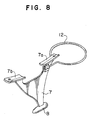
- the annular wire means provide on a fore end of the keel body means operates as follows.
- the model turns around the contact point between the annular wire means and the obstacle so that the model can easily get away from the obstacle.
- the sailing boat model becomes even more similar to an actual sailing boat with the auxiliary keel means or the auxiliary rudder means if at least a part of the auxiliary keel means or the auxiliary rudder means is made of a transparent material, as they then could not be seen in the water.
- the yacht model has a hull 1 , a keel 2 provided on the bottom of the midship portion of the hull 1, and a rudder 3 provided on the bottom of the stern portion of the hull 1.
- the hull 1 is provided with a mast 4 extending upward.
- the mast 4 is provided with a main sail 5 at its rear side, and a jib sail 6 at its front side.
- the above mentioned model has a configuration similar to that of an actual yacht, that is the hull 1, the keel 2, the rudder 3, the mast 4, the sails 5 and 6 have relative dimension which simulate an actual sailing yacht.
- the model is exhibited on a proper base frame or hung on a wall.
- an auxiliary keel 7 having a weight 8 on its lower end is provided so as to prevent the hull 1 from turning over on its side.
- the auxiliary keel 7 has connecting members 7a, 7b, each having a flange-like configuration, at its upper portion, and a cutout disposed between the connecting members 7a, 7b for preventing the auxiliary keel 7 from interfering with the keel 2.
- the auxiliary keel 7 is mounted on the hull 1 by screwing connecting screws 1b into tapped holes 1a provided on the bottom of the hull 1 and each having a construction of a cap nut for waterproofing, so as to fix the flange-like connecting members 7a, 7b on the hull 1 from its outside along the center line of the hull 1 with the cutout between connecting members 7a, 7b facing the keel 2.
- the auxiliary keel 7 can be easily connected to and disconnected from the hull 1.
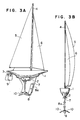
- FIGS 3A, 3B show another embodiment of the present invention.
- the auxiliary keel 7 is provided with stabilizing fins 10, 10 on both sides of the lower end of its rear portion.
- Fixed to the fore part of the auxiliary keel 7 is a connecting member 8a which is adapted to hold the weight 8 and is able to adjust the height at which the weight 8 is mounted to the keel 7.
- the stabilizing fins 10, 10 and the weight 8 can be used as a tripod to make the model stand up straight, with the auxiliary keel 7 being mounted on the hull 1.
- the connecting member 8a is mounted to the fore part of the auxiliary keel 7 by screwing the connecting member 8a on the fore part of the auxiliary keel 7 using a pair of upper tapped holes 8b, 8b or a pair of lower tapped holes 8c, 8c which are disposed on the the auxiliary keel 7 along the leading edge of the keel 7, in accordance with the height at which the weight 8 is to be mounted on the keel 7.
- the height at which the weight 8 is mounted to the keel 7 can be adjusted.
- the leading edge of the keel 7 is inclined to form a line extending toward a bow of the model with an up-grade as shown in Figure 3A so that the position of the weight 8 moves toward the stern of the model 1 as the position of the weight 8 moves downward.
- an auxiliary rudder 9 is connected to the rudder 3 by inserting the rudder 3 into a channel 9a disposed on the upper portion of the auxiliary rudder 9. Maneuverability of the model yacht is improved by using the auxiliary rudder 9.
- Figures 7A, 7B show still another embodiment of the present invention.
- the auxiliary keel 7 is provided with auxiliary buoyant means 11 made of a foaming material on both sides of its upper portion.
- the auxiliary buoyant means 11 may be made of a hollow material.
- Figure 8 shows still another embodiment of the present invention.
- the auxiliary keel 7 is provided with an annular wire 12 on its fore end.
- the yacht model becomes even more similar to the actual yacht even while retaining the auxiliary keel 7 and the auxiliary rudder 9 provided that the auxiliary keel 7 and the auxiliary rudder 9 are made of a transparent material such as transparent plastic, given that they are not visible in the water.
Landscapes
- Engineering & Computer Science (AREA)
- Ocean & Marine Engineering (AREA)
- Toys (AREA)
- Aerodynamic Tests, Hydrodynamic Tests, Wind Tunnels, And Water Tanks (AREA)
Claims (8)
- Modèle de bateau à voile convenant à l'exposition et à la navigation à voile réelle sur l'eau et comprenant une coque (1), une quille (2) montée sur la partie inférieure du milieu de la coque pour s'étendre vers le bas à partir de la coque, un safran (3) monté sur une partie inférieure de l'arrière de la coque, un mât (4) monté sur la coque pour s'étendre vers le haut à partir de la coque et une voile (5) assujettie au mât, la coque, la quille, le safran, le mât et la voile possédant des dimensions relatives qui simulent un bateau à voile réel, caractérisé par une quille auxiliaire (7) attachée de manière amovible à la partie inférieure du milieu de la coque en plus de la quille (2) et comportant une masse d'équilibre (8) montée sur l'extrémité inférieure de la quille auxiliaire afin d'abaisser le centre de gravité du modèle de bateau à voile lorsqu'on le fait naviguer sur l'eau.
- Modèle de bateau à voile suivant la revendication 1, caractérisé en ce qu'il comprend un dispositif d'ajustage (8a) pour régler la position de la masse d' équilibre (8) le long d'une ligne d'étendant vers l' avant ou la proue du modèle de bateau à voile avec une pente ascendante.
- Modèle de bateau à voile suivant la revendication 1 ou la revendication 2, comprenant également des ailerons de stabilisation (10) montés sur l'extrémité inférieure du corps de la quille (7).
- Modèle de bateau à voile suivant l'une quelconque des revendications précédentes, caractérisé en ce qu'il comprend un moyen de flottabilité auxiliaire (11) monté sur une partie supérieure du corps de la quille (7).
- Modèle de bateau à voile suivant l'une quelconque des revendications précédentes, caractérisé en ce qu'il comprend un fil annulaire (12) monté sur l'extrémité avant du corps de la quille (7).
- Modèle de bateau à voile suivant l'une quelconque des revendications précédentes, caractérisé en ce qu'au moins une partie de la quille auxiliaire (7) est réalisée en un matériau transparent.
- Modèle de bateau à voile suivant l'une quelconque des revendications précédentes, caractérisé en ce qu'il comprend un safran auxiliaire (9) attaché de manière amovible au safran (3).
- Modèle de bateau à voile suivant la revendication 7, caractérisé en ce qu'au moins une partie du safran auxiliaire (9) est réalisée en un matériau transparent.
Applications Claiming Priority (2)
| Application Number | Priority Date | Filing Date | Title |
|---|---|---|---|
| JP181744/90 | 1990-07-10 | ||
| JP2181744A JPH0661393B2 (ja) | 1990-07-10 | 1990-07-10 | 水上帆走および展示に適した帆船模型 |
Publications (3)
| Publication Number | Publication Date |
|---|---|
| EP0465745A2 EP0465745A2 (fr) | 1992-01-15 |
| EP0465745A3 EP0465745A3 (en) | 1992-03-18 |
| EP0465745B1 true EP0465745B1 (fr) | 1994-12-28 |
Family
ID=16106129
Family Applications (1)
| Application Number | Title | Priority Date | Filing Date |
|---|---|---|---|
| EP90311911A Expired - Lifetime EP0465745B1 (fr) | 1990-07-10 | 1990-10-31 | Modèle de bateau à voile adapté pour exposition et pour naviguer |
Country Status (4)
| Country | Link |
|---|---|
| US (1) | US5069648A (fr) |
| EP (1) | EP0465745B1 (fr) |
| JP (1) | JPH0661393B2 (fr) |
| DE (1) | DE69015628T2 (fr) |
Families Citing this family (16)
| Publication number | Priority date | Publication date | Assignee | Title |
|---|---|---|---|---|
| USD373156S (en) | 1994-02-03 | 1996-08-27 | Bruce Kirby, Inc. | Model sailboat |
| US5784976A (en) * | 1997-02-05 | 1998-07-28 | Burdick; James F. | Weighted daggerboard stabilizer for wind surfing apparatus |
| WO1998033701A1 (fr) * | 1997-02-05 | 1998-08-06 | Burdick James F | Derive lestee stabilisatrice pour planche a voile |
| NZ336760A (en) * | 1999-07-12 | 2002-09-27 | Dianne Conroy | Water craft for fishing with sail that can be moved from raised to lowered position by operator from shore |
| JP2002369745A (ja) * | 2001-06-15 | 2002-12-24 | Taimatsu Shokuhin Kk | 鏡餅お飾りセット |
| USD476703S1 (en) | 2001-10-03 | 2003-07-01 | Golden Bright Manufacturer Ltd. | Toy radio control sailing boat |
| CN101475051B (zh) * | 2008-01-02 | 2010-11-10 | 北京有色金属研究总院 | 帆船用船体外挂式抗风浪钨合金平衡锤 |
| US7784417B2 (en) * | 2008-11-13 | 2010-08-31 | Jensen Christian H | Sailboat with a canting ballast system |
| JP5316607B2 (ja) | 2010-08-11 | 2013-10-16 | 横浜ゴム株式会社 | タイヤパンクシール材 |
| US9474983B2 (en) | 2012-05-16 | 2016-10-25 | Toyosity, LLC | Surfing toy |
| US10525369B2 (en) | 2012-05-16 | 2020-01-07 | Toyosity, LLC | Interchangeable components for water and convertible toys |
| US9352239B2 (en) | 2012-05-16 | 2016-05-31 | Toyosity, LLC | Toy surfboard |
| USD711485S1 (en) | 2013-03-05 | 2014-08-19 | Toyosity, LLC | Toy surfboard |
| US8894460B1 (en) | 2012-05-16 | 2014-11-25 | Toyosity, LLC | Toy surfboard |
| CN109612632A (zh) * | 2018-11-02 | 2019-04-12 | 中国航空工业集团公司西安飞机设计研究所 | 一种通用飞机方向舵重量平衡检查方法 |
| US20250318517A1 (en) * | 2024-02-15 | 2025-10-16 | Warren Nicholas Smith | Keel for a bird decoy |
Family Cites Families (10)
| Publication number | Priority date | Publication date | Assignee | Title |
|---|---|---|---|---|
| US685648A (en) * | 1901-06-04 | 1901-10-29 | Albert Schoenhut | Boat. |
| GB234280A (en) * | 1924-05-22 | 1925-05-28 | George Stevenson | Improvements in toy or model vessels |
| DE443786C (de) * | 1925-02-19 | 1927-05-06 | Carl August Hefter | Faltboot fuer Spielzwecke |
| US1918543A (en) * | 1931-07-27 | 1933-07-18 | Chein & Company J | Sail boat |
| GB413930A (en) * | 1933-11-13 | 1934-07-26 | Alfred Mallory Todd | Improvements relating to toy boats |
| GB1115663A (en) * | 1966-03-01 | 1968-05-29 | Willem Frederik Vonck | Improvements in yachts having centre-boards |
| US3871127A (en) * | 1973-01-04 | 1975-03-18 | Desmond Heath | Model sailing ship |
| DE3227348A1 (de) * | 1982-07-22 | 1984-02-02 | Harald 3015 Wennigsen Diesinger | Hebe- und rettungseinrichtung fuer schiffe |
| US4548149A (en) * | 1983-11-04 | 1985-10-22 | Del Raso Americo | Rudder for aquatic craft |
| US4599964A (en) * | 1984-12-21 | 1986-07-15 | Kenney Thomas A | Sailboat hull |
-
1990
- 1990-07-10 JP JP2181744A patent/JPH0661393B2/ja not_active Expired - Lifetime
- 1990-10-30 US US07/605,375 patent/US5069648A/en not_active Expired - Fee Related
- 1990-10-31 EP EP90311911A patent/EP0465745B1/fr not_active Expired - Lifetime
- 1990-10-31 DE DE69015628T patent/DE69015628T2/de not_active Expired - Fee Related
Also Published As
| Publication number | Publication date |
|---|---|
| EP0465745A3 (en) | 1992-03-18 |
| DE69015628D1 (de) | 1995-02-09 |
| JPH0661393B2 (ja) | 1994-08-17 |
| EP0465745A2 (fr) | 1992-01-15 |
| JPH0471587A (ja) | 1992-03-06 |
| DE69015628T2 (de) | 1995-05-11 |
| US5069648A (en) | 1991-12-03 |
Similar Documents
| Publication | Publication Date | Title |
|---|---|---|
| EP0465745B1 (fr) | Modèle de bateau à voile adapté pour exposition et pour naviguer | |
| US5063869A (en) | Wing type sailing yacht | |
| US5471942A (en) | Hydrofoil sailboard with supercavitating canard hydrofoil | |
| US3762353A (en) | High speed sailboat | |
| US6789490B2 (en) | Ship constructions for achieving stability at high speed through the use of multiple, low wave-making resistance, submerged hullform pods and control fins | |
| WO1987002320A1 (fr) | Catamaran rapide a auto-redressement | |
| US6789489B1 (en) | Sailboat with gimbaled mast and keel | |
| US20020046690A1 (en) | Elevated tow apparatus | |
| US4843987A (en) | Heel counteracting airfoil | |
| EP0855984B1 (fr) | Trimaran a ailes portantes | |
| JPH0788199B2 (ja) | 帆艇および帆船の推進装置 | |
| US3561388A (en) | Hydrofoil saling craft | |
| US4599964A (en) | Sailboat hull | |
| US4280428A (en) | Non-heeling sailboat | |
| US6453839B2 (en) | Self stabilizing tow apparatus | |
| EP0152461B1 (fr) | Structures de quilles pour bateaux a voile | |
| US6325009B1 (en) | Sailboat for sailing in shallow water | |
| US4381725A (en) | Actuators for small sailing craft | |
| US4784075A (en) | Watercraft with righting aid | |
| US4829925A (en) | Multiple mode sail driven vehicle | |
| US4284027A (en) | Boat with canted wing fins | |
| US4686923A (en) | Sailboat keel having a cantilevered trailing edge flap | |
| US6382121B2 (en) | Boat ballast system | |
| JP2615348B2 (ja) | 船体に翼状環を有した転覆防止装置 | |
| US5263433A (en) | Hybrid hydrofoil strut leading edge extension |
Legal Events
| Date | Code | Title | Description |
|---|---|---|---|
| PUAI | Public reference made under article 153(3) epc to a published international application that has entered the european phase |
Free format text: ORIGINAL CODE: 0009012 |
|
| 17P | Request for examination filed |
Effective date: 19901221 |
|
| AK | Designated contracting states |
Kind code of ref document: A2 Designated state(s): DE GB |
|
| PUAL | Search report despatched |
Free format text: ORIGINAL CODE: 0009013 |
|
| AK | Designated contracting states |
Kind code of ref document: A3 Designated state(s): DE GB |
|
| 17Q | First examination report despatched |
Effective date: 19930928 |
|
| GRAA | (expected) grant |
Free format text: ORIGINAL CODE: 0009210 |
|
| AK | Designated contracting states |
Kind code of ref document: B1 Designated state(s): DE GB |
|
| REF | Corresponds to: |
Ref document number: 69015628 Country of ref document: DE Date of ref document: 19950209 |
|
| PLBE | No opposition filed within time limit |
Free format text: ORIGINAL CODE: 0009261 |
|
| STAA | Information on the status of an ep patent application or granted ep patent |
Free format text: STATUS: NO OPPOSITION FILED WITHIN TIME LIMIT |
|
| 26N | No opposition filed | ||
| PGFP | Annual fee paid to national office [announced via postgrant information from national office to epo] |
Ref country code: DE Payment date: 19981030 Year of fee payment: 9 |
|
| PGFP | Annual fee paid to national office [announced via postgrant information from national office to epo] |
Ref country code: GB Payment date: 19981106 Year of fee payment: 9 |
|
| PG25 | Lapsed in a contracting state [announced via postgrant information from national office to epo] |
Ref country code: GB Free format text: LAPSE BECAUSE OF NON-PAYMENT OF DUE FEES Effective date: 19991031 |
|
| GBPC | Gb: european patent ceased through non-payment of renewal fee |
Effective date: 19991031 |
|
| PG25 | Lapsed in a contracting state [announced via postgrant information from national office to epo] |
Ref country code: DE Free format text: LAPSE BECAUSE OF NON-PAYMENT OF DUE FEES Effective date: 20000801 |