EP0465773A2 - Extruder with a vent zone - Google Patents
Extruder with a vent zone Download PDFInfo
- Publication number
- EP0465773A2 EP0465773A2 EP91106289A EP91106289A EP0465773A2 EP 0465773 A2 EP0465773 A2 EP 0465773A2 EP 91106289 A EP91106289 A EP 91106289A EP 91106289 A EP91106289 A EP 91106289A EP 0465773 A2 EP0465773 A2 EP 0465773A2
- Authority
- EP
- European Patent Office
- Prior art keywords
- extruder
- pressure
- entrainer
- melt
- housing
- Prior art date
- Legal status (The legal status is an assumption and is not a legal conclusion. Google has not performed a legal analysis and makes no representation as to the accuracy of the status listed.)
- Withdrawn
Links
Images
Classifications
-
- B—PERFORMING OPERATIONS; TRANSPORTING
- B30—PRESSES
- B30B—PRESSES IN GENERAL
- B30B11/00—Presses specially adapted for forming shaped articles from material in particulate or plastic state, e.g. briquetting presses, tabletting presses
- B30B11/22—Extrusion presses; Dies therefor
- B30B11/24—Extrusion presses; Dies therefor using screws or worms
- B30B11/241—Drive means therefor; screw bearings
-
- B—PERFORMING OPERATIONS; TRANSPORTING
- B29—WORKING OF PLASTICS; WORKING OF SUBSTANCES IN A PLASTIC STATE IN GENERAL
- B29B—PREPARATION OR PRETREATMENT OF THE MATERIAL TO BE SHAPED; MAKING GRANULES OR PREFORMS; RECOVERY OF PLASTICS OR OTHER CONSTITUENTS OF WASTE MATERIAL CONTAINING PLASTICS
- B29B7/00—Mixing; Kneading
- B29B7/30—Mixing; Kneading continuous, with mechanical mixing or kneading devices
- B29B7/34—Mixing; Kneading continuous, with mechanical mixing or kneading devices with movable mixing or kneading devices
- B29B7/38—Mixing; Kneading continuous, with mechanical mixing or kneading devices with movable mixing or kneading devices rotary
- B29B7/46—Mixing; Kneading continuous, with mechanical mixing or kneading devices with movable mixing or kneading devices rotary with more than one shaft
- B29B7/48—Mixing; Kneading continuous, with mechanical mixing or kneading devices with movable mixing or kneading devices rotary with more than one shaft with intermeshing devices, e.g. screws
- B29B7/482—Mixing; Kneading continuous, with mechanical mixing or kneading devices with movable mixing or kneading devices rotary with more than one shaft with intermeshing devices, e.g. screws provided with screw parts in addition to other mixing parts, e.g. paddles, gears, discs
- B29B7/483—Mixing; Kneading continuous, with mechanical mixing or kneading devices with movable mixing or kneading devices rotary with more than one shaft with intermeshing devices, e.g. screws provided with screw parts in addition to other mixing parts, e.g. paddles, gears, discs the other mixing parts being discs perpendicular to the screw axis
-
- B—PERFORMING OPERATIONS; TRANSPORTING
- B29—WORKING OF PLASTICS; WORKING OF SUBSTANCES IN A PLASTIC STATE IN GENERAL
- B29B—PREPARATION OR PRETREATMENT OF THE MATERIAL TO BE SHAPED; MAKING GRANULES OR PREFORMS; RECOVERY OF PLASTICS OR OTHER CONSTITUENTS OF WASTE MATERIAL CONTAINING PLASTICS
- B29B7/00—Mixing; Kneading
- B29B7/30—Mixing; Kneading continuous, with mechanical mixing or kneading devices
- B29B7/34—Mixing; Kneading continuous, with mechanical mixing or kneading devices with movable mixing or kneading devices
- B29B7/38—Mixing; Kneading continuous, with mechanical mixing or kneading devices with movable mixing or kneading devices rotary
- B29B7/46—Mixing; Kneading continuous, with mechanical mixing or kneading devices with movable mixing or kneading devices rotary with more than one shaft
- B29B7/48—Mixing; Kneading continuous, with mechanical mixing or kneading devices with movable mixing or kneading devices rotary with more than one shaft with intermeshing devices, e.g. screws
- B29B7/488—Parts, e.g. casings, sealings; Accessories, e.g. flow controlling or throttling devices
-
- B—PERFORMING OPERATIONS; TRANSPORTING
- B29—WORKING OF PLASTICS; WORKING OF SUBSTANCES IN A PLASTIC STATE IN GENERAL
- B29B—PREPARATION OR PRETREATMENT OF THE MATERIAL TO BE SHAPED; MAKING GRANULES OR PREFORMS; RECOVERY OF PLASTICS OR OTHER CONSTITUENTS OF WASTE MATERIAL CONTAINING PLASTICS
- B29B7/00—Mixing; Kneading
- B29B7/30—Mixing; Kneading continuous, with mechanical mixing or kneading devices
- B29B7/58—Component parts, details or accessories; Auxiliary operations
- B29B7/72—Measuring, controlling or regulating
- B29B7/726—Measuring properties of mixture, e.g. temperature or density
-
- B—PERFORMING OPERATIONS; TRANSPORTING
- B29—WORKING OF PLASTICS; WORKING OF SUBSTANCES IN A PLASTIC STATE IN GENERAL
- B29B—PREPARATION OR PRETREATMENT OF THE MATERIAL TO BE SHAPED; MAKING GRANULES OR PREFORMS; RECOVERY OF PLASTICS OR OTHER CONSTITUENTS OF WASTE MATERIAL CONTAINING PLASTICS
- B29B7/00—Mixing; Kneading
- B29B7/80—Component parts, details or accessories; Auxiliary operations
- B29B7/84—Venting or degassing ; Removing liquids, e.g. by evaporating components
- B29B7/845—Venting, degassing or removing evaporated components in devices with rotary stirrers
-
- B—PERFORMING OPERATIONS; TRANSPORTING
- B29—WORKING OF PLASTICS; WORKING OF SUBSTANCES IN A PLASTIC STATE IN GENERAL
- B29B—PREPARATION OR PRETREATMENT OF THE MATERIAL TO BE SHAPED; MAKING GRANULES OR PREFORMS; RECOVERY OF PLASTICS OR OTHER CONSTITUENTS OF WASTE MATERIAL CONTAINING PLASTICS
- B29B7/00—Mixing; Kneading
- B29B7/80—Component parts, details or accessories; Auxiliary operations
- B29B7/88—Adding charges, i.e. additives
- B29B7/94—Liquid charges
-
- B—PERFORMING OPERATIONS; TRANSPORTING
- B29—WORKING OF PLASTICS; WORKING OF SUBSTANCES IN A PLASTIC STATE IN GENERAL
- B29C—SHAPING OR JOINING OF PLASTICS; SHAPING OF MATERIAL IN A PLASTIC STATE, NOT OTHERWISE PROVIDED FOR; AFTER-TREATMENT OF THE SHAPED PRODUCTS, e.g. REPAIRING
- B29C48/00—Extrusion moulding, i.e. expressing the moulding material through a die or nozzle which imparts the desired form; Apparatus therefor
- B29C48/25—Component parts, details or accessories; Auxiliary operations
- B29C48/252—Drive or actuation means; Transmission means; Screw supporting means
- B29C48/2522—Shaft or screw supports, e.g. bearings
-
- B—PERFORMING OPERATIONS; TRANSPORTING
- B29—WORKING OF PLASTICS; WORKING OF SUBSTANCES IN A PLASTIC STATE IN GENERAL
- B29C—SHAPING OR JOINING OF PLASTICS; SHAPING OF MATERIAL IN A PLASTIC STATE, NOT OTHERWISE PROVIDED FOR; AFTER-TREATMENT OF THE SHAPED PRODUCTS, e.g. REPAIRING
- B29C48/00—Extrusion moulding, i.e. expressing the moulding material through a die or nozzle which imparts the desired form; Apparatus therefor
- B29C48/25—Component parts, details or accessories; Auxiliary operations
- B29C48/268—Throttling of the flow, e.g. for cooperating with plasticising elements or for degassing
-
- B—PERFORMING OPERATIONS; TRANSPORTING
- B29—WORKING OF PLASTICS; WORKING OF SUBSTANCES IN A PLASTIC STATE IN GENERAL
- B29C—SHAPING OR JOINING OF PLASTICS; SHAPING OF MATERIAL IN A PLASTIC STATE, NOT OTHERWISE PROVIDED FOR; AFTER-TREATMENT OF THE SHAPED PRODUCTS, e.g. REPAIRING
- B29C48/00—Extrusion moulding, i.e. expressing the moulding material through a die or nozzle which imparts the desired form; Apparatus therefor
- B29C48/25—Component parts, details or accessories; Auxiliary operations
- B29C48/36—Means for plasticising or homogenising the moulding material or forcing it through the nozzle or die
- B29C48/395—Means for plasticising or homogenising the moulding material or forcing it through the nozzle or die using screws surrounded by a cooperating barrel, e.g. single screw extruders
- B29C48/40—Means for plasticising or homogenising the moulding material or forcing it through the nozzle or die using screws surrounded by a cooperating barrel, e.g. single screw extruders using two or more parallel screws or at least two parallel non-intermeshing screws, e.g. twin screw extruders
- B29C48/405—Intermeshing co-rotating screws
-
- B—PERFORMING OPERATIONS; TRANSPORTING
- B29—WORKING OF PLASTICS; WORKING OF SUBSTANCES IN A PLASTIC STATE IN GENERAL
- B29C—SHAPING OR JOINING OF PLASTICS; SHAPING OF MATERIAL IN A PLASTIC STATE, NOT OTHERWISE PROVIDED FOR; AFTER-TREATMENT OF THE SHAPED PRODUCTS, e.g. REPAIRING
- B29C48/00—Extrusion moulding, i.e. expressing the moulding material through a die or nozzle which imparts the desired form; Apparatus therefor
- B29C48/25—Component parts, details or accessories; Auxiliary operations
- B29C48/36—Means for plasticising or homogenising the moulding material or forcing it through the nozzle or die
- B29C48/50—Details of extruders
- B29C48/76—Venting, drying means; Degassing means
- B29C48/765—Venting, drying means; Degassing means in the extruder apparatus
- B29C48/766—Venting, drying means; Degassing means in the extruder apparatus in screw extruders
- B29C48/767—Venting, drying means; Degassing means in the extruder apparatus in screw extruders through a degassing opening of a barrel
-
- B—PERFORMING OPERATIONS; TRANSPORTING
- B29—WORKING OF PLASTICS; WORKING OF SUBSTANCES IN A PLASTIC STATE IN GENERAL
- B29C—SHAPING OR JOINING OF PLASTICS; SHAPING OF MATERIAL IN A PLASTIC STATE, NOT OTHERWISE PROVIDED FOR; AFTER-TREATMENT OF THE SHAPED PRODUCTS, e.g. REPAIRING
- B29C48/00—Extrusion moulding, i.e. expressing the moulding material through a die or nozzle which imparts the desired form; Apparatus therefor
- B29C48/25—Component parts, details or accessories; Auxiliary operations
- B29C48/92—Measuring, controlling or regulating
-
- B—PERFORMING OPERATIONS; TRANSPORTING
- B29—WORKING OF PLASTICS; WORKING OF SUBSTANCES IN A PLASTIC STATE IN GENERAL
- B29B—PREPARATION OR PRETREATMENT OF THE MATERIAL TO BE SHAPED; MAKING GRANULES OR PREFORMS; RECOVERY OF PLASTICS OR OTHER CONSTITUENTS OF WASTE MATERIAL CONTAINING PLASTICS
- B29B7/00—Mixing; Kneading
- B29B7/74—Mixing; Kneading using other mixers or combinations of mixers, e.g. of dissimilar mixers ; Plant
- B29B7/7404—Mixing devices specially adapted for foamable substances
-
- B—PERFORMING OPERATIONS; TRANSPORTING
- B29—WORKING OF PLASTICS; WORKING OF SUBSTANCES IN A PLASTIC STATE IN GENERAL
- B29B—PREPARATION OR PRETREATMENT OF THE MATERIAL TO BE SHAPED; MAKING GRANULES OR PREFORMS; RECOVERY OF PLASTICS OR OTHER CONSTITUENTS OF WASTE MATERIAL CONTAINING PLASTICS
- B29B7/00—Mixing; Kneading
- B29B7/80—Component parts, details or accessories; Auxiliary operations
- B29B7/86—Component parts, details or accessories; Auxiliary operations for working at sub- or superatmospheric pressure
-
- B—PERFORMING OPERATIONS; TRANSPORTING
- B29—WORKING OF PLASTICS; WORKING OF SUBSTANCES IN A PLASTIC STATE IN GENERAL
- B29C—SHAPING OR JOINING OF PLASTICS; SHAPING OF MATERIAL IN A PLASTIC STATE, NOT OTHERWISE PROVIDED FOR; AFTER-TREATMENT OF THE SHAPED PRODUCTS, e.g. REPAIRING
- B29C2948/00—Indexing scheme relating to extrusion moulding
- B29C2948/92—Measuring, controlling or regulating
- B29C2948/92009—Measured parameter
- B29C2948/92019—Pressure
-
- B—PERFORMING OPERATIONS; TRANSPORTING
- B29—WORKING OF PLASTICS; WORKING OF SUBSTANCES IN A PLASTIC STATE IN GENERAL
- B29C—SHAPING OR JOINING OF PLASTICS; SHAPING OF MATERIAL IN A PLASTIC STATE, NOT OTHERWISE PROVIDED FOR; AFTER-TREATMENT OF THE SHAPED PRODUCTS, e.g. REPAIRING
- B29C2948/00—Indexing scheme relating to extrusion moulding
- B29C2948/92—Measuring, controlling or regulating
- B29C2948/92009—Measured parameter
- B29C2948/92209—Temperature
-
- B—PERFORMING OPERATIONS; TRANSPORTING
- B29—WORKING OF PLASTICS; WORKING OF SUBSTANCES IN A PLASTIC STATE IN GENERAL
- B29C—SHAPING OR JOINING OF PLASTICS; SHAPING OF MATERIAL IN A PLASTIC STATE, NOT OTHERWISE PROVIDED FOR; AFTER-TREATMENT OF THE SHAPED PRODUCTS, e.g. REPAIRING
- B29C2948/00—Indexing scheme relating to extrusion moulding
- B29C2948/92—Measuring, controlling or regulating
- B29C2948/92323—Location or phase of measurement
- B29C2948/92361—Extrusion unit
- B29C2948/9238—Feeding, melting, plasticising or pumping zones, e.g. the melt itself
-
- B—PERFORMING OPERATIONS; TRANSPORTING
- B29—WORKING OF PLASTICS; WORKING OF SUBSTANCES IN A PLASTIC STATE IN GENERAL
- B29C—SHAPING OR JOINING OF PLASTICS; SHAPING OF MATERIAL IN A PLASTIC STATE, NOT OTHERWISE PROVIDED FOR; AFTER-TREATMENT OF THE SHAPED PRODUCTS, e.g. REPAIRING
- B29C2948/00—Indexing scheme relating to extrusion moulding
- B29C2948/92—Measuring, controlling or regulating
- B29C2948/92504—Controlled parameter
- B29C2948/92514—Pressure
-
- B—PERFORMING OPERATIONS; TRANSPORTING
- B29—WORKING OF PLASTICS; WORKING OF SUBSTANCES IN A PLASTIC STATE IN GENERAL
- B29C—SHAPING OR JOINING OF PLASTICS; SHAPING OF MATERIAL IN A PLASTIC STATE, NOT OTHERWISE PROVIDED FOR; AFTER-TREATMENT OF THE SHAPED PRODUCTS, e.g. REPAIRING
- B29C2948/00—Indexing scheme relating to extrusion moulding
- B29C2948/92—Measuring, controlling or regulating
- B29C2948/92819—Location or phase of control
- B29C2948/92857—Extrusion unit
- B29C2948/92876—Feeding, melting, plasticising or pumping zones, e.g. the melt itself
-
- B—PERFORMING OPERATIONS; TRANSPORTING
- B29—WORKING OF PLASTICS; WORKING OF SUBSTANCES IN A PLASTIC STATE IN GENERAL
- B29C—SHAPING OR JOINING OF PLASTICS; SHAPING OF MATERIAL IN A PLASTIC STATE, NOT OTHERWISE PROVIDED FOR; AFTER-TREATMENT OF THE SHAPED PRODUCTS, e.g. REPAIRING
- B29C48/00—Extrusion moulding, i.e. expressing the moulding material through a die or nozzle which imparts the desired form; Apparatus therefor
- B29C48/03—Extrusion moulding, i.e. expressing the moulding material through a die or nozzle which imparts the desired form; Apparatus therefor characterised by the shape of the extruded material at extrusion
- B29C48/07—Flat, e.g. panels
- B29C48/08—Flat, e.g. panels flexible, e.g. films
-
- B—PERFORMING OPERATIONS; TRANSPORTING
- B29—WORKING OF PLASTICS; WORKING OF SUBSTANCES IN A PLASTIC STATE IN GENERAL
- B29C—SHAPING OR JOINING OF PLASTICS; SHAPING OF MATERIAL IN A PLASTIC STATE, NOT OTHERWISE PROVIDED FOR; AFTER-TREATMENT OF THE SHAPED PRODUCTS, e.g. REPAIRING
- B29C48/00—Extrusion moulding, i.e. expressing the moulding material through a die or nozzle which imparts the desired form; Apparatus therefor
- B29C48/25—Component parts, details or accessories; Auxiliary operations
- B29C48/36—Means for plasticising or homogenising the moulding material or forcing it through the nozzle or die
- B29C48/50—Details of extruders
- B29C48/76—Venting, drying means; Degassing means
- B29C48/762—Vapour stripping
Definitions
- the invention relates to a twin-screw extruder according to the preamble of claim 1.
- thermoplastics there is often a need to remove residual monomers from the starting plastic.
- the proportion of residual monomers that are harmful to health must not exceed a certain limit for food law and therefore medical reasons.
- the polystyrene normally to be fed in an extruder has a proportion of up to 100,000 ppm of monomeric styrene, a very effective degassing device is required in order to be able to reach the limit value for residual monomers in the product, which is about two orders of magnitude lower.
- the residual monomer content in the product that can be achieved with such single-screw extruders is not sufficient for many areas, especially not if the plastic products come into direct contact with food, for example.
- the diameter of the upstream adjusting ring should be essentially the same as that of the outer diameter of an extruder screw, but the diameter of the locking ring located downstream from the injection point should be somewhat larger than that of the adjusting ring.
- the gusset area can be narrowed on one side and thereby regulate the flow rate between the inner wall of the cylinder and the adjusting rings and thus the pressure in the extruder.
- a melt flow that has reached the injection area between the setting and blocking rings is brought into contact with the injected water here using kneading elements on the extruder screws. The water evaporates on contact with the melt and leads to foaming in the neighboring degassing area of the extruder.
- the object of the invention is to propose a method and a twin-screw extruder in which the degassing efficiency can be increased even further by better mixing the melt with the injected entrainer.
- the idea of the invention is based on the knowledge that optimal degassing of the melt is only possible if the blowing agent has been mixed completely and homogeneously in the melt. This is the only way to allow the melt in the degassing area of the extruder Degas strong bubbles so strongly that the food-law limit values can be observed.
- the melt pressure must be increased to a value which is above the evaporation pressure of the entrainer. Once this has been achieved, the entrainer and the melt can easily be mixed with one another in the liquid phase and then relaxed under the degassing opening of the extruder with vigorous bubble formation. In this way, the melt is almost completely degassed.
- the necessary increase in pressure of the melt can be achieved according to the invention with the aid of an eyeglass-shaped pressure orifice which is exchangeably fastened in the extruder at a preselected location in the extruder, closely downstream of the water injection point.
- This pressure orifice is non-positively connected to the extruder housing via centering elements and blocks the processing space of the extruder downstream except for a maximum of two passage openings for the extrudate.
- the continuous pressure plate prevents pressure loss due to the unwanted premature flow of the melt into the expansion area of the extruder.
- the housing 1 shows the housing 1 of a degassing twin-screw extruder to which a drive unit 18 is connected.
- the extruder can be fed with a monomer-containing melt or a monomer-containing granulate of a plastic via a filling opening 13.
- the extruder screws 2, 3 rotating in the extruder housing convey the plastic from a feed zone a to a processing zone b, in which the plastic is plasticized and brought to the required pressure.
- Water can be supplied to the plastic melt via an entrainer injection opening 14 in the extruder housing 1. This water is mixed in the extruder section c with the plastic melt at a pressure which prevents evaporation of the water and, if desired, the pressure of the mixture is further increased here.
- the pressure and the temperature of the melt close to the injection opening 14 are continuously determined with the aid of temperature and pressure sensors 16, 19 and used as a control variable for the extruder operation.
- process zone c is formed by pressure orifice 4, which is only shown in phantom in this drawing.
- a vacuum pump (not shown) is connected to the degassing opening 15 of the extruder housing 1 in a manner known per se.
- FIG. 2 shows the extruder housing 1 cut open in the area in which the pressure orifice 4 is arranged.
- the pressure orifice 4 at this point connects the screws 2, 3 in such a positive manner that no melt can flow off over the gusset area of the processing space 10. Rather, an eyeglass-shaped passage opening 21 is created between the pressure orifice 4 and the inner wall of the extruder housing, through which the melt-water mixture can reach the degassing zone d of the extruder (FIG. 3).
- the extruder screws 2, 3 are constructed from screw shafts 5, 6 and screw sleeves 2a, 3a mounted thereon and braced with them.
- the screw sleeves 2a, 3a are interrupted in the area of the orifice and pushed onto the screw shafts 5, 6 with replaceable wear or sealing rings 7, 8. This measure allows the pressure orifice 4 so well when assembling and pulling in the screws 2, 3 into the extruder housing that the centering elements 11 which can be inserted from the outside through the extruder housing exactly meet the holes 12 provided in the pressure orifice 4.
- the centering elements 11 are conical in order to facilitate their insertion into the bores 12 of the pressure orifice 4.
- the centering elements 11 form an angle of preferably 40 to 180 ° with respect to the axis of rotation of an extruder screw 2, 3 in pairs.
- the section of the extruder housing which serves to fix the pressure orifice 4 can advantageously be produced6 as a pressure orifice housing part which, when such a pressure orifice 4 is used, can be installed as an additional housing section in an already existing extruder housing.
- the partial diameter D and the depth of the pressure orifice 4 must be selected. As a rule, this diameter D will be chosen so that it is less than or equal to the diameter F of an extruder screw.
- the wear or sealing rings 7, 8 can also be mounted on the screw sleeves 2a, 3a, which are now reduced in diameter.
- FIGS. 4, 5 show a further possibility of how the object of the invention can be carried out.
- the snails 2, 3 of the extruder in its housing 1 comprises an eyeglass-shaped pressure aperture 4 which are non-positively connected to the housing 1 by centering elements 11.
- the pressure orifice 4 closes in a form-fitting manner with the inner wall of the extruder housing, but also covers the gusset area of the processing space 10 here.
- the pressure orifice 4 extends only so far to the web-free screw sleeves 2a, 3a that a passage opening 21a, 21b is formed for each extruder screw 2, 3.
- the radial width of such a passage can be freely selected, but must not be so large that the two passages 21a, 21b touch to form a gusset (FIG. 5).
Landscapes
- Engineering & Computer Science (AREA)
- Mechanical Engineering (AREA)
- Extrusion Moulding Of Plastics Or The Like (AREA)
- Processing And Handling Of Plastics And Other Materials For Molding In General (AREA)
Abstract
Es wird ein Verfahren und ein Doppelschneckenextruder zur Entgasung einer thermoplastischen, monomerhaltigen Kunststoffschmelze vorgestellt, bei dem die Kunststoffschmelze und ein Schleppmittel unter einem Druck miteinander vermischt werden, der einen Übergang des Schleppmittels von seiner flüssigen in seine gasförmige Phase verhindert. Der dafür notwendige Druck im Extruder ist mit Hilfe einer brillenförmigen Druckblende (4) erzielbar, die über Zentrierelemente kraftschlüssig mit dem Extrudergehäuse (1) verbunden ist und den Verarbeitungsraum des Extruders bis auf maximal zwei Durchlaßöffnungen für das Extrudat stromabwärts absperrt.
Description
Die Erfindung betrifft einen Doppelschneckenextruder gemäß dem Oberbegriff des Anspruchs 1.The invention relates to a twin-screw extruder according to the preamble of
Bei der Herstellung von thermoplastischen Kunststoffen besteht häufig das Bedürfnis, Restmonomere aus dem Ausgangskunststoff zu entfernen. Soll beispielsweise eine Verpackungsfolie für Lebensmittel aus Polystyrol extrudiert werden, so darf aus lebensmittelrechtlichen und damit aus medizinischen Gründen der Anteil von gesundheitlich schädlichen Restmonomeren einen bestimmten Grenzwert nicht übersteigen. Da das üblicherweise in einem Extruder einzuspeisende Polystyrol einen Anteil von bis zu 100.000 ppm monomeres Styrol aufweist, bedarf es einer sehr effektiven Entgasungsvorrichtung, um den um etwa zwei Zehnerpotenzen niedrigeren Grenzwert für Restmonomere im Produkt erreichen zu können.In the production of thermoplastics, there is often a need to remove residual monomers from the starting plastic. For example, if a packaging film for food is to be extruded from polystyrene, the proportion of residual monomers that are harmful to health must not exceed a certain limit for food law and therefore medical reasons. Since the polystyrene normally to be fed in an extruder has a proportion of up to 100,000 ppm of monomeric styrene, a very effective degassing device is required in order to be able to reach the limit value for residual monomers in the product, which is about two orders of magnitude lower.
Zur Entgasung von derartigen Kunststoffen ist seit langem bekannt, bei Einschneckenextrudern eine Einspritzstelle für ein Schleppmittel vorzusehen, mit dem die Kunststoffschmelze im Extruder vermischt wird. Dieses Schleppmittel (in der Regel Wasser) sorgt dann in einem der Einspritzstelle stromabwärts nachgeordneten Entgasungsbereich dafür, daß die Schmelze bei einer Druckabsenkung aufschäumt. Die durch die Schaumblasen verursachte Vergrößerung der freien Oberfläche der Schmelze bewirkt so eine für weite Anwendungsbereiche ausreichende Entgasung der Schmelze.For the degassing of such plastics, it has long been known In the case of single-screw extruders, an injection point for an entrainer must be provided, with which the plastic melt is mixed in the extruder. This entrainer (usually water) then ensures in a degassing area downstream of the injection point that the melt foams when the pressure drops. The increase in the free surface of the melt caused by the foam bubbles thus results in a sufficient degassing of the melt for wide areas of application.
Die mit solchen Einschneckenextrudern erzielbaren Restmonomeranteile im Produkt reichen aber für viele Gebiete nicht aus, insbesondere dann nicht, wenn die Kunststoffprodukte beispielsweise mit Lebensmitteln direkt in Kontakt geraten.However, the residual monomer content in the product that can be achieved with such single-screw extruders is not sufficient for many areas, especially not if the plastic products come into direct contact with food, for example.
So wurde in der DE-OS 26 25 609 vorgeschlagen, einen Doppelschneckenextruder für die Entgasung von restmonomerhaltigen Schmelzen vorzusehen. Bei einem Doppelschneckenextruder treten aber aufgrund seiner baulichen Eigenarten besondere Probleme auf. Vor allem der Zwickelbereich des Extruders, also der Bereich, in dem der Querschnitt des Verarbeitungsraumes des Extruders eine Engstelle aufweist, sorgt dafür, daß sich nicht der gewünschte Druck in der Schmelze aufbauen läßt, der für eine optimale Durchmischung der Schmelze mit dem Schleppmittel Wasser nötig ist.In DE-OS 26 25 609 it was proposed to provide a twin-screw extruder for the degassing of melts containing residual monomers. In a twin screw extruder, however, there are special problems due to its structural characteristics. Above all, the gusset area of the extruder, i.e. the area in which the cross-section of the processing space of the extruder has a narrow point, ensures that the desired pressure in the melt cannot be built up, which is necessary for optimal mixing of the melt with the entrainer water is.
Zur Lösung dieses Problems wurde in dieser Druckschrift vorgeschlagen, vor und nach der Einspritzstelle für das Wasser Einstell- und Sperringe vorzusehen, die auf den Extruderschnecken befestigt sind und mit diesen rotieren. Dabei soll der Durchmesser des stromaufwärtigen Einstellringes im wesentlichen derselbe sein wie der des Außendurchmessers einer Extruderschnecke, der Durchmesser des von der Einspritzstelle stromabwärts gelegenen Sperringes aber etwas größer sein als der des Einstellringes.To solve this problem, it was proposed in this document to provide adjusting and locking rings before and after the injection point for the water, which are attached to the extruder screws and rotate with them. The diameter of the upstream adjusting ring should be essentially the same as that of the outer diameter of an extruder screw, but the diameter of the locking ring located downstream from the injection point should be somewhat larger than that of the adjusting ring.
Mit Hilfe eines in den Verarbeitungsraum ragenden, im wesentlichen V-förmigen und an die Kreisbögen der Einstellringe angepaßten Stellzylinders läßt sich der Zwickelbereich einseitig einengen und dadurch in gewisser Weise die Fördermenge zwischen der Zylinderinnenwand und den Einstellringen und damit der Druck im Extruder regulieren. Ein solchermaßen in den Einspritzbereich zwischen den Einstell- und Sperringen gelangter Schmelzestrom wird hier mit dem eingespritzen Wasser mit Hilfe von Knetelementen auf den Extruderschnecken in Kontakt gebracht. Das Wasser verdampft beim Kontakt mit der Schmelze und führt zu einem Aufschäumen im benachbarten Entgasungsbereich des Extruders.With the help of a protruding into the processing space, essentially V-shaped and adapted to the circular arcs of the adjusting rings, the gusset area can be narrowed on one side and thereby regulate the flow rate between the inner wall of the cylinder and the adjusting rings and thus the pressure in the extruder. A melt flow that has reached the injection area between the setting and blocking rings is brought into contact with the injected water here using kneading elements on the extruder screws. The water evaporates on contact with the melt and leads to foaming in the neighboring degassing area of the extruder.
Zwar ist die Entgasungseffektivität eines solchen Extruders besser als die eines Doppelschneckenextruders ohne die vorgeschlagenen Maßnahmen zur Steuerung des in den Knetbereich gelangenden Schmelzestroms, nachteilig ist aber, daß das eingespritzte Wasser sofort bei seiner Berührung mit der Schmelze verdampft und daher nur eine sehr schlechte Durchmischung von Wasser und Schmelze stattfindet.Although the degassing effectiveness of such an extruder is better than that of a twin-screw extruder without the proposed measures for controlling the melt stream entering the kneading area, it is disadvantageous that the injected water evaporates immediately when it comes into contact with the melt and therefore only a very poor mixing of water and melt takes place.
Demgemäß liegt der Erfindung die Aufgabe zugrunde, ein Verfahren und einen Doppelschneckenextruder vorzuschlagen, bei dem der Entgasungswirkungsgrad durch eine bessere Vermischung der Schmelze mit dem eingespritzten Schleppmittel noch weiter gesteigert werden kann.Accordingly, the object of the invention is to propose a method and a twin-screw extruder in which the degassing efficiency can be increased even further by better mixing the melt with the injected entrainer.
Die Lösung dieser Aufgabe ergibt sich aus den kennzeichnenden Merkmalen des Hauptanspruchs. Weiterbildungen und vorteilhafte Ausgestaltungen der Erfindung sind den Unteransprüchen zu entnehmen.The solution to this problem results from the characterizing features of the main claim. Further developments and advantageous refinements of the invention can be found in the subclaims.
Dem Erfindungsgedanken liegt die Erkenntnis zugrunde, daß eine optimale Entgasung der Schmelze nur dann möglich ist, wenn das Treibmittel vollständig und homogen in der Schmelze vermischt wurde. Nur so läßt sich im Entgasungsbereich des Extruders die Schmelze unter möglichst starker Blasenbildung derart stark entgasen, daß die lebensmittelrechtlichen Grenzwerte eingehalten werden können.The idea of the invention is based on the knowledge that optimal degassing of the melt is only possible if the blowing agent has been mixed completely and homogeneously in the melt. This is the only way to allow the melt in the degassing area of the extruder Degas strong bubbles so strongly that the food-law limit values can be observed.
Um diese vollständige Vermischung des Wassers mit der Schmelze erreichen zu können, bedarf es einer Erhöhung des Schmelzedruckes auf einen Wert, der über dem Verdampfungsdruck des Schleppmittels liegt. Ist dieser erreicht, lassen sich das Schleppmittel und die Schmelze in flüssiger Phase leicht miteinander vermischen und anschließend unter der Entgasungsöffnung des Extruders unter starker Blasenbildung entspannen. Auf diese Art und Weise wird die Schmelze fast vollständig entgast.In order to achieve this complete mixing of the water with the melt, the melt pressure must be increased to a value which is above the evaporation pressure of the entrainer. Once this has been achieved, the entrainer and the melt can easily be mixed with one another in the liquid phase and then relaxed under the degassing opening of the extruder with vigorous bubble formation. In this way, the melt is almost completely degassed.
Die notwendige Druckerhöhung der Schmelze läßt sich erfindungsgemäß mit Hilfe einer brillenförmigen Druckblende erreichen, die an einer vorgewählten Stelle im Extruder dicht stromabwärts von der Wassereinspritzstelle austauschbar im Extruder befestigt ist.The necessary increase in pressure of the melt can be achieved according to the invention with the aid of an eyeglass-shaped pressure orifice which is exchangeably fastened in the extruder at a preselected location in the extruder, closely downstream of the water injection point.
Diese Druckblende ist über Zentrierelemente mit dem Extrudergehäuse kraftschlüssig verbunden sperrt den Verarbeitungsraum des Extruders stromabwärts bis auf maximal zwei Durchlaßöffnungen für das Extrudat ab. Insbesondere im für den Druckaufbau wichtigen Zwickelbereich im Verarbeitungsraum des Extruders verhindert das durchgehende Druckblendenblech einen Druckverlust durch das unerwünschte vorzeitige Abströmen der Schmelze in den Expansionsbereich des Extruders.This pressure orifice is non-positively connected to the extruder housing via centering elements and blocks the processing space of the extruder downstream except for a maximum of two passage openings for the extrudate. Especially in the gusset area in the processing area of the extruder, which is important for pressure build-up, the continuous pressure plate prevents pressure loss due to the unwanted premature flow of the melt into the expansion area of the extruder.
Die Erfindung läßt sich mit Hilfe der Zeichnung anhand von Ausführungsbeispielen erläutern.The invention can be explained with the aid of the drawings using exemplary embodiments.
Es zeigen:
- Fig. 1
- eine schematische Darstellung des Entgasungsdoppelschneckenextruders.
- Fig. 2
- einen Blick in ein längsseitig aufgeschnittenes Gehäuse des Extruders.
- Fig. 3
- einen Schnitt AA durch das Extrudergehäuse gemäß Fig. 2.
- Fig. 4
- eine Ansicht des Extruders gemäß Fig. 2, jedoch in einer anderen Ausführungsform.
- Fig. 5
- einen Schnitt BB durch das Extrudergehäuse gemäß Fig. 4.
- Fig. 1
- a schematic representation of the degassing twin-screw extruder.
- Fig. 2
- a look into a longitudinally cut housing of the extruder.
- Fig. 3
- 3 shows a section AA through the extruder housing according to FIG. 2.
- Fig. 4
- a view of the extruder of FIG. 2, but in another embodiment.
- Fig. 5
- 4 shows a section BB through the extruder housing according to FIG. 4.
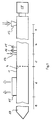
In Fig. 1 ist das Gehäuse 1 eines Entgasungsdoppelschneckenextruders dargestellt, an dem eine Antriebseinheit 18 angeschlossen ist. Über eine Einfüllöffnung 13 ist der Extruder mit einer monomerhaltigen Schmelze oder einem monomerhaltigem Granulat eines Kunststoffs speisbar. Die im Extrudergehäuse rotierenden Extruderschnecken 2, 3 befördern den Kunststoff aus einer Einzugszone a zu einer Verfahrenszone b, in der der Kunststoff plastifiziert und auf den erforderlichen Druck gebracht wird.1 shows the
Über eine Schleppmitteleinspritzöffnung 14 im Extrudergehäuse 1 ist der Kunststoffschmelze Wasser zuführbar. Dieses Wasser wird im Extruderabschnitt c mit der Kunststoffschmelze bei einem Druck vermischt, der ein Verdampfen des Wassers verhindert und, sofern gewünscht, wird hier der Druck des Gemisches weiter erhöht.Water can be supplied to the plastic melt via an entrainer injection opening 14 in the
In einer vorteilhaften Ausgestaltung der Erfindung wird der Druck und die Temperatur der Schmelze dicht bei der Einspritzöffnung 14 ständig mit Hilfe von Temperatur- und Drucksensoren 16, 19 ermittelt und als Regelgröße für den Extruderbetrieb verwendet.In an advantageous embodiment of the invention, the pressure and the temperature of the melt close to the
Den Abschluß der Verfahrenszone c bildet die Druckblende 4, die in dieser Zeichnung nur phantomhaft dargestellt ist.The end of process zone c is formed by
Hinter der Druckblende 4 entspannt sich das Gemisch aus Kunststoff und Wasser unter starker Blasenbildung in der Entgasungszone d. Dadurch entsteht eine sehr große freie Kunststoffoberfläche, aus der die Monomere und das Wasser entgasen können. Um den Entgasungsvorgang zu unterstützen, ist in an sich bekannter Weise an der Entgasungsöffnung 15 des Extrudergehäuses 1 eine nicht dargestellte Vakuumpumpe angeschlossen.Behind the
Nachdem die Schmelze vom Wasser und von den Monomeren weitestgehend befreit ist, kann sie in einem Extruderabschnitt e erneut unter Druck gebracht werden, um anschließend durch ein Extrusionswerkzeug 17 den Extruder zu verlassen.After the melt and the monomers have largely been freed from the melt, it can be pressurized again in an extruder section e in order to then leave the extruder by means of an
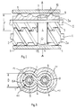
In Fig. 2 ist in einem Ausführungsbeispiel der Erfindung das Extrudergehäuse 1 in dem Bereich aufgeschnitten dargestellt, in dem die Druckblende 4 angeordnet ist. Die Druckblende 4 verbindet an dieser Stelle die Schnecken 2, 3 derart formschlüssig, daß über den Zwickelbereich des Verarbeitungsraumes 10 keine Schmelze abfließen kann. Vielmehr wird zwischen der Druckblende 4 und der Innenwand des Extrudergehäuses eine brillenförmige Durchlaßöffnung 21 geschaffen, durch die das Schmelze-Wasser-Gemisch in die Entgasungszone d des Extruders gelangen kann (Figur 3).In an exemplary embodiment of the invention, FIG. 2 shows the
In diesem Beispiels sind die Extruderschnecken 2, 3 aus Schneckenschäften 5, 6 und darauf aufgezogenen und mit diesen verspannten Schneckenhülsen 2a, 3a aufgebaut. Zur Aufnahme der Druckblende 4 sind die Schneckenhülsen 2a, 3a im Blendenbereich unterbrochen und mit auswechselbaren Verschleiß- oder Dichtringen 7, 8 auf die Schneckenschäfte 5, 6 aufgeschoben. Durch diese Maßnahme läßt sich die Druckblende 4 beim Zusammenbau und beim Einziehen der Schnecken 2, 3 in das Extrudergehäuse derart gut positionieren, daß die von außen durch das Extrudergehäuse einführbaren Zentrierelemente 11 die in der Druckblende 4 vorgesehenen Bohrungen 12 exakt treffen.In this example, the extruder screws 2, 3 are constructed from
Die Zentrierelemente 11 sind in vorteilhafter Ausgestaltung der Erfindung konisch ausgebildet, um ihr Einführen in die Bohrungen 12 der Druckblende 4 zu erleichtern. Zudem ist vorgesehen, daß die Zentrierelemente 11 bezogen auf die Drehachse einer Extruderschnecke 2, 3 paarweise zueinander einen Winkel von vorzugsweise 40 bis 180° bilden. Der Teilbereich des Extrudergehäuses, der zur Fixierung der Druckblende 4 dient, kann in vorteilhafter Weise als Druckblenden-Gehäuseteil gefertigt6 sein, der beim Einsatz einer solchen Druckblende 4 als zusätzlicher Gehäsueabschnitt in ein bereits vorhandenes Extrudergehäuse einbaubar ist.In an advantageous embodiment of the invention, the centering
In Abhängigkeit von den gewünschten Extrusionsbedingungen ist der Teildurchmesser D und die Tiefe der Druckblende 4 zu wählen. In der Regel wird dieser Durchmesser D so gewählt sein, daß er kleiner oder gleich dem Durchmesser F einer Extruderschnecke ist.Depending on the desired extrusion conditions, the partial diameter D and the depth of the
In einer nicht dargestellten Variante der Erfindung lassen sich die Verschleiß- oder Dichtringe 7, 8 auch auf den nun aber in ihrem Durchmesser reduzierten Schneckenhülsen 2a, 3a lagern.In a variant of the invention, not shown, the wear or sealing
Zur besseren Montierbarkeit der Druckblende 4 auf den Schnecken 2, 3 kann diese entlang einer die Drehachsen der Schnecken 2, 3 verbindenden Geraden 20 zweigeteilt und über Verbindungselemente mit einander verbindbar sein.For better assembly of the
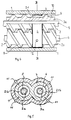
In den Figuren 4, 5 ist eine weitere Möglichkeit dargestellt, wie der Erfindungsgegenstand ausführbar ist. Auch hier werden die Schnecken 2, 3 des Extruders in dessen Gehäuse 1 von einer brillenförmigen Druckblende 4 umfaßt, die von Zentrierelementen 11 mit dem Gehäuse 1 kraftschlüssig verbunden sind. Allerdings schließt die Druckblende 4 formschlüssig mit der Innenwand des Extrudergehäuses ab, überdeckt aber auch hier den Zwickelbereich des Verarbeitungsraumes 10.FIGS. 4, 5 show a further possibility of how the object of the invention can be carried out. Again, the snails 2, 3 of the extruder in its
Um dem Gemisch aus Schmelze und Schleppmittel einen Durchlaß zur Entgasungszone zu schaffen, erstreckt sich die Druckblende 4 nur soweit auf die hier stegfreien Schneckenhülsen 2a, 3a zu, daß je Extruderschnecke 2, 3 eine Durchlaßöffnung 21a, 21b ausgebildet wird. Die radiale Weite eines solchen Durchlasses ist frei wählbar, darf aber nicht so groß sein, daß sich die beiden Durchlässe 21a, 21b unter Bildung eines Zwickels berühren (Figur 5).In order to create a passage to the degassing zone for the mixture of melt and entrainer, the
Außerdem besteht auch hier die Möglichkeit, die Schneckenhülsen 2a, 3a im Bereich der Druckblende 4 zu unterbrechen und die Durchlaßöffnungen 21a, 21b bis auf die Oberfläche der Schneckenschäfte 5, 6 reichen zu lassen.In addition, there is also the possibility here of interrupting the
- 1 =1 =
- Gehäusecasing
- 2 =2 =
- ExtruderschneckeExtruder screw
- 2a =2a =
- SchneckenhülseScrew sleeve
- 3 =3 =
- ExtruderschneckeExtruder screw
- 3a =3a =
- SchneckenhülseScrew sleeve
- 4 =4 =
- DruckblendePressure aperture
- 5 =5 =
- SchneckenschaftSnail shaft
- 6 =6 =
- SchneckenschaftSnail shaft
- 7 =7 =
- Verschleißring / DichtringWear ring / sealing ring
- 8 =8 =
- Verschleißring / DichtringWear ring / sealing ring
- 9 =9 =
- SchneckenstegSnail bridge
- 10 =10 =
- VerarbeitungsraumProcessing room
- 11 =11 =
- ZentrierelementCentering element
- 12 =12 =
- Bohrungdrilling
- 13 =13 =
- EinfüllöffnungFilling opening
- 14 =14 =
- SchleppmitteleinspritzöffnungEntrainer injection opening
- 15 =15 =
- EntgasungsöffnungDegassing opening
- 16 =16 =
- DrucksensorPressure sensor
- 17 =17 =
- ExtruderdüseExtruder nozzle
- 18 =18 =
- Antriebdrive
- 19 =19 =
- TemperatursensorTemperature sensor
- 20 =20 =
- Trennlinie zwischen oberer und unterer DruckblendenhälfteDividing line between the upper and lower pressure orifice half
- 21 =21 =
- Durchlaßöffnung in der DruckblendePassage opening in the pressure orifice
- 21a =21a =
- Durchlaßöffnung in der DruckblendePassage opening in the pressure orifice
- 21b =21b =
- Durchlaßöffnung in der DruckblendePassage opening in the pressure orifice
- a =a =
- EinzugszoneCatchment area
- b =b =
- Plastifizier- und DruckaufbauzonePlasticizing and pressure build-up zone
- c =c =
- MischzoneMixing zone
- d =d =
- EntgasungszoneDegassing zone
- e =e =
- DruckaufbauzonePressure build-up zone
- D =D =
- Teildurchmesser der DruckblendePartial diameter of the pressure orifice
- F =F =
- Durchmesser ExtruderschneckeExtruder screw diameter
Claims (16)
gekennzeichnet durch folgende Verfahrensschritte,
characterized by the following process steps,
dadurch gekennzeichnet,
daß als thermoplastischer Kunststoff Polystyrol mit monomeren Styrolresten verwendet wird.Method according to claim 1,
characterized,
that polystyrene with monomeric styrene residues is used as the thermoplastic.
dadurch gekennzeichnet,
daß als Schleppmittel Wasser verwendet wird.Method according to claim 1,
characterized,
that water is used as an entrainer.
dadurch gekennzeichnet,
daß der Schmelzedruck und die Schmelzetemperatur dicht bei der Einspritzstelle für das Schleppmittel gemessen wird.Method according to claim 1,
characterized,
that the melt pressure and the melt temperature are measured close to the injection point for the entrainer.
dadurch gekennzeichnet,
daß das Monomer und das verdampfte Schleppmittel aus dem Extruder abgesaugt werden.Method according to claim 1,
characterized,
that the monomer and the evaporated entrainer are sucked out of the extruder.
dadurch gekennzeichnet,
daß der Druck des Gemisches aus Schmelze und Schleppmittel nach dem Einspritzen des Schleppmittels weiter erhöht wird.Method according to claim 1,
characterized,
that the pressure of the mixture of melt and entrainer is further increased after the entrainer has been injected.
dadurch gekennzeichnet,
daß dieses Bauteil eine brillenförmige Druckblende (4) ist,
daß die Druckblende (4) über Zentrierelemente (11) kraftschlüssig mit dem Extrudergehäuse (1) verbunden ist, und daß die Druckblende (4) den Verarbeitungsraum (10) bis auf maximal zwei Durchlaßöffnungen (21 bzw. 21a, 21b) für das Extrudat stromabwärts absperrt.Double-screw extruder for carrying out the method according to claim 1, consisting of an extruder housing with two hollow cylindrical bores forming a processing space, which extend and intersect parallel to the longitudinal axis of the extruder housing, two extruder screws rotatably mounted in this housing about their longitudinal axes and on the drive side, a filling opening for the thermoplastic to be processed, at least one injection opening in the housing for the injection of an entrainer, at least one degassing opening, an extrusion head and a component which is arranged upstream of the degassing opening to increase the pressure of the melt in the extruder,
characterized,
that this component is an eyeglass-shaped pressure screen (4),
that the pressure orifice (4) is non-positively connected to the extruder housing (1) via centering elements (11), and that the pressure orifice (4) downstream of the extrudate except for a maximum of two passage openings (21 or 21a, 21b) for the extrudate cordoned off.
dadurch gekennzeichnet,
daß die Durchlaßöffnung (21) zwischen der Innenwand des Extrudergehäuses (1) und der Druckblende (4) gebildet wird, wobei die Druckblende (4) über Verschleiß- oder Dichtringe (7, 8) auf den Schäften (5, 6) oder den Schneckenhülsen (2a, 3a) formschlüssig aufliegt.Twin screw extruder according to claim 7,
characterized,
that the passage opening (21) is formed between the inner wall of the extruder housing (1) and the pressure orifice (4), the pressure orifice (4) via wear or sealing rings (7, 8) on the shafts (5, 6) or the screw sleeves (2a, 3a) rests positively.
dadurch gekennzeichnet,
daß die Durchlaßöffnungen (21a, 21b) zwischen den Schneckenschäften (5, 6) oder den Schneckenhülsen (2a, 3a) gebildet werden, wobei die Druckblende (4) den Verarbeitungsraum (10) formschlüssig zur Innenwand des Extrudergehäuses (1) abdichtet.Twin screw extruder according to claim 7,
characterized,
that the passage openings (21a, 21b) are formed between the screw shafts (5, 6) or the screw sleeves (2a, 3a), the pressure orifice (4) sealingly sealing the processing space (10) from the inner wall of the extruder housing (1).
dadurch gekennzeichnet,
daß die Schneckenhülsen (2a, 3a) im Bereich der Druckblende (4) in ihrem Durchmesser verringert oder unterbrochen ausgeführt sind.Twin screw extruder according to claims 8 and 9,
characterized,
that the screw sleeves (2a, 3a) in the area of the pressure orifice (4) have a reduced or interrupted diameter.
dadurch gekennzeichnet,
daß die Zentrierelemente (11) konisch ausgebildet sind.Twin screw extruder according to claim 7,
characterized,
that the centering elements (11) are conical.
dadurch gekennzeichnet,
daß die Zentrierelemente (11) bezogen auf die Drehachse einer Extruderschnecke (2, 3) paarweise zueinander einen Winkel von vorzugsweise 40 bis 180° bilden.Twin screw extruder according to claims 7 and 11,
characterized,
that the centering elements (11) form an angle of preferably 40 to 180 ° in pairs with respect to the axis of rotation of an extruder screw (2, 3).
dadurch gekennzeichnet,
daß die Druckblende (4) entlang einer die Drehachsen der Extruderschnecken (2, 3) verbindenden Geraden (20) zweigeteilt und über Verbindungselemente miteinander verbindbar sind.Twin screw extruder according to claim 7,
characterized,
that the pressure orifice (4) is divided in two along a straight line (20) connecting the axes of rotation of the extruder screws (2, 3) and can be connected to one another via connecting elements.
dadurch gekennzeichnet,
daß der Teildurchmesser D der Druckblende (4) kleiner oder gleich ist als der Durchmesser F einer Extruderschnecke.Twin screw extruder according to claim 6,
characterized,
that the partial diameter D of the pressure orifice (4) is less than or equal to the diameter F of an extruder screw.
dadurch gekennzeichnet,
daß die Druckblende (4) über auswechselbare Verschleiß- oder Dichtringe (7, 8) mit den Hülsen (2a, 3a) oder den Schäften (5, 6) der Extruderschnecken (2, 3) form- und/oder kraftschlüssig verbunden ist.Twin screw extruder according to claim 7,
characterized,
that the pressure orifice (4) is connected to the sleeves (2a, 3a) or the shafts (5, 6) of the extruder screws (2, 3) in a positive and / or non-positive manner via exchangeable wear or sealing rings (7, 8).
dadurch gekennzeichnet,
daß die Durchlaßöffnungen (21a, 21b) in der Druckblende (4) derart klein gehalten werden, daß sie im Zwickelbereich des Extruders nicht zu einer einzigen Durchlaßöffnung verschmelzen.Twin screw extruder according to claim 9,
characterized,
that the passage openings (21a, 21b) in the pressure aperture (4) are kept so small that they do not fuse into a single passage opening in the gusset area of the extruder.
Applications Claiming Priority (2)
| Application Number | Priority Date | Filing Date | Title |
|---|---|---|---|
| DE4021751 | 1990-07-07 | ||
| DE4021751A DE4021751A1 (en) | 1990-07-07 | 1990-07-07 | DEGASSING EXTRUDERS |
Publications (2)
| Publication Number | Publication Date |
|---|---|
| EP0465773A2 true EP0465773A2 (en) | 1992-01-15 |
| EP0465773A3 EP0465773A3 (en) | 1992-04-01 |
Family
ID=6409907
Family Applications (1)
| Application Number | Title | Priority Date | Filing Date |
|---|---|---|---|
| EP19910106289 Withdrawn EP0465773A3 (en) | 1990-07-07 | 1991-04-19 | Extruder with a vent zone |
Country Status (4)
| Country | Link |
|---|---|
| US (1) | US5125824A (en) |
| EP (1) | EP0465773A3 (en) |
| JP (1) | JPH04232721A (en) |
| DE (1) | DE4021751A1 (en) |
Cited By (3)
| Publication number | Priority date | Publication date | Assignee | Title |
|---|---|---|---|---|
| EP1252999A1 (en) | 2001-04-25 | 2002-10-30 | Kabushiki Kaisha Kobe Seiko Sho (Kobe Steel, Ltd.) | Kneading apparatus and method for kneading rubber-based composition using the same |
| US7419295B2 (en) * | 2004-06-21 | 2008-09-02 | Kabushiki Kaisha Kobe Seiko Sho (Kobe Steel, Ltd.) | Extruder |
| WO2022015529A1 (en) * | 2020-07-15 | 2022-01-20 | Dow Global Technologies Llc | Process for removal of contaminants from contaminated thermoplastic |
Families Citing this family (13)
| Publication number | Priority date | Publication date | Assignee | Title |
|---|---|---|---|---|
| DE4200788A1 (en) * | 1992-01-15 | 1993-07-22 | Bayer Ag | SNAIL MACHINE WITH STOCK ELEMENTS |
| DE4211149A1 (en) * | 1992-04-03 | 1993-10-07 | Bayer Ag | Multi-shaft screw machine with gear pump |
| DE4444285C2 (en) * | 1993-12-14 | 1996-11-28 | Kobe Steel Ltd | Device for forming waste material containing waste paper and its use |
| JP2000044669A (en) * | 1998-08-04 | 2000-02-15 | Teijin Ltd | Method for producing aromatic polycarbonate and vacuum collecting system |
| US6280667B1 (en) | 1999-04-19 | 2001-08-28 | Andersen Corporation | Process for making thermoplastic-biofiber composite materials and articles including a poly(vinylchloride) component |
| US6388001B1 (en) * | 1999-12-21 | 2002-05-14 | General Electric Company | Compounding filled silicone compositions |
| DE10132688A1 (en) * | 2001-07-05 | 2003-01-30 | Bayer Ag | Bottom bracket for screw machines |
| DE102011052015A1 (en) | 2010-11-26 | 2012-05-31 | Reluma Gmbh | Intrusion method for producing e.g. lamp posts, involves determining required amount of polyethylene and required portion of plastic molding mass to be mixed into another molding mass, and mixing portion of former mass with latter mass |
| WO2012037932A2 (en) | 2010-08-03 | 2012-03-29 | Reluma Gmbh | Method for producing three-dimensional objects from recycled plastic waste by pressure intrusion |
| US8864486B2 (en) * | 2013-03-15 | 2014-10-21 | Corning Incorporated | Twin screw shaft spacer bearing |
| DE102013108369A1 (en) | 2013-04-11 | 2014-10-16 | Mondi Gronau Gmbh | Process for producing a flexible film for disposable hygiene products |
| CN107106355B (en) | 2014-11-06 | 2020-11-03 | 宝洁公司 | Crimped Fiber Spunbond Nonwoven Web/Laminate |
| US12127925B2 (en) | 2018-04-17 | 2024-10-29 | The Procter & Gamble Company | Webs for absorbent articles and methods of making the same |
Family Cites Families (12)
| Publication number | Priority date | Publication date | Assignee | Title |
|---|---|---|---|---|
| DE158014C (en) * | ||||
| US3391232A (en) * | 1964-08-12 | 1968-07-02 | Du Pont | Forming process regulation |
| DE1554751B1 (en) * | 1966-09-10 | 1971-01-07 | Kestermann Maschf Rolf | Screw extruder |
| US3917507A (en) * | 1971-02-22 | 1975-11-04 | Welding Engineers | Countercurrent combined liquid and vapor stripping in screw devolatilizer |
| DE2321325A1 (en) * | 1973-04-27 | 1974-11-14 | Werner & Pfleiderer | Twin screw plasticiser with shearing section - having coaxial sleeves keyed to screws and barrel |
| JPS5111882A (en) * | 1974-07-20 | 1976-01-30 | Sumitomo Chemical Co | Mihannotanryotaio jokyosuruhoho |
| US3963558A (en) * | 1974-12-09 | 1976-06-15 | W Bar E, Incorporated | Apparatus and method for producing solid polymeric material from a dilute polymer solution |
| JPS5249267A (en) * | 1975-10-17 | 1977-04-20 | Japan Steel Works Ltd | Degassing modifying extruder |
| CA1073170A (en) * | 1975-11-28 | 1980-03-11 | David B. Todd | Multi-barrel continuous material processing machine with a multi-positionable flow controlling saddle part |
| DE2654774C3 (en) * | 1976-12-03 | 1981-10-15 | Werner & Pfleiderer, 7000 Stuttgart | Screw machine for homogenizing melted polymers |
| DE2924800C2 (en) * | 1979-06-20 | 1982-08-19 | Werner & Pfleiderer, 7000 Stuttgart | Throttle device for a twin-screw screw machine |
| NL8102930A (en) * | 1981-06-17 | 1983-01-17 | Stamicarbon | METHOD FOR PREPARING POLYMER MELTS FREE OF VOLATILE COMPONENTS |
-
1990
- 1990-07-07 DE DE4021751A patent/DE4021751A1/en active Granted
-
1991
- 1991-04-19 EP EP19910106289 patent/EP0465773A3/en not_active Withdrawn
- 1991-07-03 US US07/725,681 patent/US5125824A/en not_active Expired - Fee Related
- 1991-07-05 JP JP3165757A patent/JPH04232721A/en not_active Withdrawn
Cited By (5)
| Publication number | Priority date | Publication date | Assignee | Title |
|---|---|---|---|---|
| EP1252999A1 (en) | 2001-04-25 | 2002-10-30 | Kabushiki Kaisha Kobe Seiko Sho (Kobe Steel, Ltd.) | Kneading apparatus and method for kneading rubber-based composition using the same |
| US7004616B2 (en) | 2001-04-25 | 2006-02-28 | Kobe Steel, Ltd. | Kneading apparatus and method for kneading rubber-based composition using the same |
| US8177412B2 (en) | 2001-04-25 | 2012-05-15 | Kobe Steel, Ltd. | Kneading apparatus and method for kneading rubber-based composition using the same |
| US7419295B2 (en) * | 2004-06-21 | 2008-09-02 | Kabushiki Kaisha Kobe Seiko Sho (Kobe Steel, Ltd.) | Extruder |
| WO2022015529A1 (en) * | 2020-07-15 | 2022-01-20 | Dow Global Technologies Llc | Process for removal of contaminants from contaminated thermoplastic |
Also Published As
| Publication number | Publication date |
|---|---|
| JPH04232721A (en) | 1992-08-21 |
| DE4021751A1 (en) | 1992-01-16 |
| EP0465773A3 (en) | 1992-04-01 |
| DE4021751C2 (en) | 1992-04-16 |
| US5125824A (en) | 1992-06-30 |
Similar Documents
| Publication | Publication Date | Title |
|---|---|---|
| EP0087699B1 (en) | Multiaxial machine for continuously mixing and kneading plastifiable material, having intermeshing screws rotating in the same direction and at a constant distance between the axes | |
| DE4021751C2 (en) | ||
| EP3880429B1 (en) | DEGASING EXTRUDER WITH A MULTI-SHELL UNIT AND METHOD FOR DEGASING POLYMER MELTING | |
| DE3150719A1 (en) | SNAIL EXTRUDERS | |
| EP3648946A1 (en) | Device and method for the extrusion of thermo-mechanically deformable materials in bulk form, and compact screw extruder | |
| DE10233213B4 (en) | extruder | |
| EP2212090B1 (en) | Screw for a screw extruder | |
| EP0090257B1 (en) | Mixing apparatus for producing a chemically reactive mixture of at least two liquid plastics components | |
| DE3711328C1 (en) | Degassing device for screw extruders | |
| DE10342822B4 (en) | Extruder for producing syntactic plastic | |
| EP3564005B1 (en) | Mixing and kneading device, and its use | |
| DE4114541C2 (en) | Degassing extruder | |
| DD231314A5 (en) | DEVOLATILIZING MIXING EXTRUDER | |
| DE4126390A1 (en) | MIXING AND TREATMENT DEVICE WITH DISCHARGE PUMP | |
| DE1936418A1 (en) | Device for processing highly viscous materials, especially rubber mixtures, in single-screw extruders | |
| WO2013013916A1 (en) | Device for degassing thermoplastic extrudate | |
| DE2537915C3 (en) | Mixing and kneading device for an extrusion press for plasticizing thermoplastics | |
| DE19810791A1 (en) | Dual-screw extruder removing volatile liquids from thermoplastic melt | |
| DE102020006486B4 (en) | Device for extruding plastics | |
| DE2435807B2 (en) | DEVICE FOR CONTROLLING THE PRESSURE AND FLOW SPEED OF PLASTIC MATERIALS IN A SCREW EXTRUDER | |
| DE1052673B (en) | Wide slot nozzle for the production of foils and sheets made of thermoplastics | |
| DE3823222C2 (en) | ||
| WO1998010910A1 (en) | Extruder to produce plastic granules | |
| DE2327540A1 (en) | Mixing unit for screw extruder - comprising coaxial rotary mixing sleeve, driven at differential angular velocity | |
| EP0816048A1 (en) | Two stage extruder and method for extruding elastomers and plastics |
Legal Events
| Date | Code | Title | Description |
|---|---|---|---|
| PUAI | Public reference made under article 153(3) epc to a published international application that has entered the european phase |
Free format text: ORIGINAL CODE: 0009012 |
|
| AK | Designated contracting states |
Kind code of ref document: A2 Designated state(s): BE DE FR GB IT |
|
| PUAL | Search report despatched |
Free format text: ORIGINAL CODE: 0009013 |
|
| AK | Designated contracting states |
Kind code of ref document: A3 Designated state(s): BE DE FR GB IT |
|
| 17P | Request for examination filed |
Effective date: 19920227 |
|
| STAA | Information on the status of an ep patent application or granted ep patent |
Free format text: STATUS: THE APPLICATION HAS BEEN WITHDRAWN |
|
| 18W | Application withdrawn |
Withdrawal date: 19930304 |