EP0465881A2 - Capteur de force avec anneau de torsion - Google Patents
Capteur de force avec anneau de torsion Download PDFInfo
- Publication number
- EP0465881A2 EP0465881A2 EP91110008A EP91110008A EP0465881A2 EP 0465881 A2 EP0465881 A2 EP 0465881A2 EP 91110008 A EP91110008 A EP 91110008A EP 91110008 A EP91110008 A EP 91110008A EP 0465881 A2 EP0465881 A2 EP 0465881A2
- Authority
- EP
- European Patent Office
- Prior art keywords
- ring
- sensor
- housing
- sensor according
- decoupling
- Prior art date
- Legal status (The legal status is an assumption and is not a legal conclusion. Google has not performed a legal analysis and makes no representation as to the accuracy of the status listed.)
- Granted
Links
Images

Classifications
-
- G—PHYSICS
- G01—MEASURING; TESTING
- G01L—MEASURING FORCE, STRESS, TORQUE, WORK, MECHANICAL POWER, MECHANICAL EFFICIENCY, OR FLUID PRESSURE
- G01L1/00—Measuring force or stress, in general
- G01L1/26—Auxiliary measures taken, or devices used, in connection with the measurement of force, e.g. for preventing influence of transverse components of force, for preventing overload
-
- G—PHYSICS
- G01—MEASURING; TESTING
- G01L—MEASURING FORCE, STRESS, TORQUE, WORK, MECHANICAL POWER, MECHANICAL EFFICIENCY, OR FLUID PRESSURE
- G01L1/00—Measuring force or stress, in general
- G01L1/20—Measuring force or stress, in general by measuring variations in ohmic resistance of solid materials or of electrically-conductive fluids; by making use of electrokinetic cells, i.e. liquid-containing cells wherein an electrical potential is produced or varied upon the application of stress
- G01L1/22—Measuring force or stress, in general by measuring variations in ohmic resistance of solid materials or of electrically-conductive fluids; by making use of electrokinetic cells, i.e. liquid-containing cells wherein an electrical potential is produced or varied upon the application of stress using resistance strain gauges
- G01L1/2206—Special supports with preselected places to mount the resistance strain gauges; Mounting of supports
- G01L1/2231—Special supports with preselected places to mount the resistance strain gauges; Mounting of supports the supports being disc- or ring-shaped, adapted for measuring a force along a single direction
Definitions
- the invention relates to a force transducer with a torsion ring for measuring forces in a wide force range.
- Transducers of this type are, for. B. used in practice for weighing trucks and railroad cars. Further applications are in the field of high-performance weight monitoring in process engineering and in the field of material testing machines.
- Transducers of the above type are generally described in a brochure entitled "New Developments in Force Measurement” by Joseph H. Antkowiak and others, published by Hottinger Baldwin Measurements, Inc. Marlboro, MA 01752.
- This type of transducer has been designed with regard to its structure and function have many advantages, e.g. B. a transducer of this type is highly accurate, has a relatively low height and the load or force to be measured can be applied in several practical ways.
- transducers of this type do not need any elaborate documents that have to be designed to record large moments. Nevertheless, further improvements are possible, especially with regard to the elimination of undesired assembly influences and undesired influences that can arise from an eccentric load application. The manufacturing costs can also be reduced further.
- 4,811,610 also requires a deep groove between the sensor ring and the ring housing, this deep groove having a narrow radial width b between the sensor ring and the ring housing.
- the groove width b is determined or designed relative to the radial width 1 of the sensor ring or the deformation body. the groove must be deep so that the requirement that the web thickness t does not exceed 1/6 the height h of the sensor ring can be met. Furthermore, the groove width b must be less than a third of the radial width 1 of the sensor ring.
- the design conditions of the known weighing cell are undesirable because even modern machine tools have difficulty cutting such narrow, deep grooves, because the cutting tools themselves have to have certain minimal dimensions in order to absorb the forces that occur.
- the tool dimensions usually do not allow the narrow, deep, axially aligned grooves to be made without taking special precautions, while maintaining economical cutting speeds.
- Assembly influences or "variables” are influences that change the measurement result, so that it is difficult to achieve constantly repeatable results if the same transducer model is mounted on different documents, or even if the assembly screws do not all at the same assembly at different times are tightened evenly. Similar irregular measurement results are achieved when the mounting surfaces have different surface properties, e.g. B. different roughness or the surfaces are not exactly flat.
- the assembly influences mentioned are substantially prevented from influencing the measurement results in an undesirable manner, it being not intended to start with specific web and groove dimensions.
- the transducer according to the invention should be less sensitive to eccentric loads or force application, in particular by equalizing the tensile and compressive stresses in the transducer, so that sufficient insensitivity to eccentric force application is achieved.
- the object on which the invention is based is achieved in a sensor of the type mentioned at the outset for measuring Forces in a target range with an above maximum limit of the permissible load are solved in that a device for decoupling assembly influences is arranged between a ring housing and a mounting foot of the transducer, one end of the decoupling device being connected to the ring housing and the other end of the decoupling device being connected to the mounting foot is to keep assembly influences away from the sensor ring.
- the sensor ring of a force transducer is so effectively decoupled from its mounting base without decoupling from the transducer housing, so that consistent measurement results are achieved.
- the decoupling device prevents forces that do not belong to the forces to be measured and assembly influences from reaching the sensor ring.
- Such assembly influences result from the fact that the assembly foot must be attached to a base or a support.
- the elimination of these influences is desirable because these influences influence the measurement results in an undesirable manner.
- the invention ensures that there are no manufacturing difficulties and that existing machine tools can be used without further ado, which apply an economical cutting speed, without the tools having to meet special conditions.
- the transducer according to the invention has a lower overall height and a significantly reduced weight when the transducer according to the invention is compared with conventional transducers of comparable measurement performance.
- a preferred embodiment according to the invention provides a ring cylinder as the decoupling device, which has a special axial wall length and a certain wall thickness.
- One end of the decoupling ring cylinder is operatively connected to the mounting base of the sensor, while the other end of the cylinder is firmly connected to the outer ring housing of the sensor.
- the sensor ring is deformed by the load to be measured.
- the sensor ring is held concentrically between two ring webs between the outer ring housing and an inner load introduction body.
- the decoupling ring cylinder has an axial wall length W l and a radial cylinder wall thickness W t .
- lengths and wall thicknesses are selected so that the ratio W l : W t lies in an area whose upper limit is sufficient to avoid kinking the ring cylinder when the maximum permissible load is applied.
- This maximum permissible load is determined by the specified target load of the transducer in question.
- the length and wall thickness are also determined by a lower limit value, which essentially ensures that the assembly influences that are effective on the assembly base cannot reach the sensor ring.
- the decoupling ring cylinder ensures that the assembly influences caused by attaching the mounting base of the transducer or the load cell to a base or on a support are not able to influence the measurement results in an undesired manner, so that consistent, accurate measurement results are achieved, essentially regardless of the type of installation.
- This is achieved in a surprisingly simple manner, since the machining of the decoupling ring cylinder can be carried out particularly easily with conventional tools and with economical cutting speeds. This is possible because of narrow, deep grooves be avoided and because the cutting tools have direct access to the surfaces to be machined, with enough space for the tools, e.g. B. on the inside, direct access is guaranteed through a large hole in the mounting base.
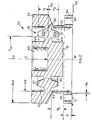
- Fig. 1 corresponds to Fig. 1 of U.S. Patent 4,811,610 (Gassmann) and shows a ring-shaped transducer or weighing cell 10 for measuring forces in a target range with an upper maximum limit of the permissible load.
- the transducer 10 has a ring housing 12, in which a load introduction body 11 is arranged centrally, a deformation-receiving sensor ring 13 with surfaces for receiving strain gauges concentrically between the ring housing 12 and the load introduction body 11 by a first radially inner force transmission web 14 and by a second radially outer power transmission web 14 'is held. So that the sensor ring 13 is held by the webs 14 and 14 'concentrically in the ring housing 12.
- the elements just described are worked out from a solid cylinder block.
- a central axis of rotation 21 ' extends vertically and centrally through the force introduction body 11.
- a neutral plane 21 extends perpendicular to the central axis 21 'and centrally through the webs 14, 14'.
- An axially upward-looking surface 19 of the sensor ring 13 carries the strain gauges 22.
- An axially downward-looking surface 20 of the sensor ring 13 carries the strain gauges 23.
- the force-transmitting webs 14, 14 ' are formed by two radially outer grooves 15 and 16 and by two radially inner grooves 17 and 18.
- the grooves 15 and 17 open upwards while the grooves 16 and 18 are open downwards.
- the radially outer grooves 15 and 16 are deep and narrow in order to achieve the desired decoupling effect.
- an axial thickness t is provided at least for the radially outer web 14 ', which is not more than a sixth of the height h of the sensor ring 13.
- the condition must also be fulfilled that the width b of the webs in the radial direction corresponds to at most one third of the width 1 of the sensor ring 13 in the radial direction.
- the radial width b of the webs corresponds in the radial direction to the width of the grooves 15 and 16.
- the invention is based on the knowledge that the decoupling of the sensor ring from the mounting base does not necessarily have to be achieved by special dimensions of the webs that connect the sensor ring to the housing. Rather, the inventor has found that a more effective decoupling with better efficiency can be achieved if the decoupler housing is decoupled from the mounting foot.
- the decoupling device 35 is preferably a ring cylinder which effectively connects the mounting foot 34 to the ring housing 33, but at the same time the transducer structure, including the housing 33, is decoupled from external influences, including and in particular assembly influences, if the mounting foot 33 is attached to a base 42, e.g. B. by threaded bolts, which are not shown, but go through the mounting holes 36 in the mounting base 34.
- the sensor ring 32 carries the strain gauge elements 37 on its axially upwardly and axially downwardly facing surfaces. Furthermore, the sensor ring 32 is connected to the ring housing 33 by a radially outer web 38. The sensor ring 32 is also connected to the force introduction body 31 by a radially inner web 39.
- the force introduction body 31 is, for. B. provided with a force introduction recess 40 which is arranged concentrically relative to the central axis of rotation 41. A force F is introduced into the force introduction body 31 with the aid of a rod, not shown, which engages in the recess 40.
- the body 31 can also be provided with a force introduction rod, which is arranged concentrically relative to the central axis of rotation 41.
- Such a rod can e.g. B. be provided with an outer thread to connect the rod with a force application device.
- the force F to be measured is introduced as coaxially as possible, relative to the central axis of rotation 41, in order to minimize effects caused by an eccentric force application to keep.
- the decoupling device 35 described above, the lower end of which is rigidly connected to the mounting foot 34 and the upper end of which is connected to the ring housing 33.
- the housing 33, the decoupling device 35 in the form of a ring cylinder, and the mounting foot 34 as well as the body 31, the sensor ring 32 and the webs 38 and 39 are machined as an integral structure from a corresponding cylindrical workpiece, with relatively simple machining operations on one lathe-like machine tool can be performed.
- the radially outer grooves 43, which form the web 38, and the radially inner grooves 44, which form the web 39, need not be particularly deep. Nor do these grooves need to be particularly narrow. This results in sufficient space for machining the radially inner surface of the decoupling ring cylinder 35.
- the radially outer surface of the cylinder 35 is similarly easily accessible for a corresponding machining tool.
- the decoupling ring cylinder 35 has an axial wall length W l and a radial cylinder wall thickness W t , which are selected so that the ratio of W l to W t lies within a range whose upper limit is sufficient to buckle the decoupling ring cylinder 35 Avoid if the maximum permissible load is initiated or if the target load capacity RC is used.
- W l and W t are also selected in such a way that the lower limit essentially keeps assembly influences and external forces away from the sensor ring.
- these dimensions W l and W t should also be selected such that the condition: F f ⁇ . RC is fulfilled, where F f represents a force which is sufficient to hold the mounting foot 34 on a base 42 against sliding, where ⁇ is a coefficient of friction between the Mounting foot and the base and where RC represents the maximum permissible target load or the permissible target capacity mentioned above. Compliance with this condition ensures that the mounting foot 34 cannot slide relative to the documents 42.
- the housing 33 has an outer housing ring diameter H od and an inner ring housing diameter H id , while the mounting foot 34 has a foot height B.
- the dimensions just mentioned and the above-mentioned axial cylinder wall length W l of the ring cylinder 35 are varied by the finite element method until the condition F f ⁇ -RC is fulfilled.
- the sensor ring 33 also has an inner ring diameter R id and an upper ring section 32a with an axial height H 1 and a lower ring section 32 b with an axial height H 2.
- the dimensions R id , H 1 and H 2 just mentioned are also based on the finite element method
- a neutral plane 45 separates the upper section 32a of the sensor ring from the lower ring section 32b, the neutral plane 45 being perpendicular to the central axis of rotation 41 and passing centrally through the webs 38 and 39.
- the force introduction recess 40 preferably extends to the neutral plane 45.
- the above-mentioned axial wall length W l and the radial wall thickness W t of the decoupling ring cylinder 35 are further selected so that S max ⁇ YP / 4 is met, where S max is the maximum stress in the decoupling ring cylinder 35 and where YP is the tear limit of the material, from which the ring cylinder 35 is made.
- S max is the maximum stress in the decoupling ring cylinder 35
- YP is the tear limit of the material, from which the ring cylinder 35 is made.
- FIG. 3 shows a ring receiver 46 of the same construction as was described above with reference to FIG. 2, including the decoupling ring cylinder 35.
- the embodiment according to FIG. 3 has a modified sensor ring 47 with surfaces 48 and 49 for fastening the strain gauges. These surfaces 48 and 49 have an angle of inclination ⁇ to the horizontal and are inclined inwards to the neutral plane 45, the transducer being less sensitive to eccentric force applications.
- This improved characteristic 50 is shown in Fig. 3a.
- FIG. 3a shows that the inclined surfaces 48, 49 make the transducer essentially insensitive to the position of the strain gauges along the inclined ring surfaces, in comparison to the characteristic 51 shown in broken lines, which relates to the radially and horizontally running surfaces for attaching the strain gauges .
- These horizontal and radial surfaces are shown in dashed lines in FIG. 3.
- the origin of the coordinate system shown in Fig. 3a lies in the radially outer edge of the inclined surfaces 48 or 49.
- These inclined surfaces 48, 49 improve the function of the transducer with respect to eccentrically introduced forces, and this is the case even when the The strain gauges 37 have not been completely completely placed on the surfaces 48, 49 concerned.
- the angle ⁇ is chosen so that the sensor sensitivity is essentially independent of the position of the strain gauges along the inclined ring surfaces mentioned above. It was found according to the invention that an angle in the range of approximately 15 to 25 ° has the desired result.
- FIG. 4 shows an embodiment of an annular sensor 52 with a deformation sensor ring 53, which has an upper ring section 54 and a lower ring section 55. Relative to the neutral plane 45, these ring sections have different axial heights H 1 and H 2.
Landscapes
- Physics & Mathematics (AREA)
- General Physics & Mathematics (AREA)
- Measurement Of Force In General (AREA)
- Force Measurement Appropriate To Specific Purposes (AREA)
- Steroid Compounds (AREA)
- Manipulator (AREA)
- Measuring Fluid Pressure (AREA)
- Pens And Brushes (AREA)
- Vehicle Body Suspensions (AREA)
- Surgical Instruments (AREA)
Applications Claiming Priority (2)
| Application Number | Priority Date | Filing Date | Title |
|---|---|---|---|
| US07/543,046 US5111702A (en) | 1990-06-22 | 1990-06-22 | Torsion ring transducer |
| US543046 | 1990-06-22 |
Publications (3)
| Publication Number | Publication Date |
|---|---|
| EP0465881A2 true EP0465881A2 (fr) | 1992-01-15 |
| EP0465881A3 EP0465881A3 (en) | 1992-09-23 |
| EP0465881B1 EP0465881B1 (fr) | 1995-08-16 |
Family
ID=24166364
Family Applications (1)
| Application Number | Title | Priority Date | Filing Date |
|---|---|---|---|
| EP91110008A Revoked EP0465881B1 (fr) | 1990-06-22 | 1991-06-19 | Capteur de force avec anneau de torsion |
Country Status (6)
| Country | Link |
|---|---|
| US (1) | US5111702A (fr) |
| EP (1) | EP0465881B1 (fr) |
| AT (1) | ATE126587T1 (fr) |
| CA (1) | CA2041049C (fr) |
| DE (1) | DE59106257D1 (fr) |
| ES (1) | ES2075916T3 (fr) |
Cited By (8)
| Publication number | Priority date | Publication date | Assignee | Title |
|---|---|---|---|---|
| GB2271185A (en) * | 1992-09-30 | 1994-04-06 | Ist Lab Ltd | Load cell |
| EP0798544A3 (fr) * | 1996-03-25 | 1998-08-26 | Schenck Process GmbH | Capteur de pesage |
| EP1793211A3 (fr) * | 2005-11-30 | 2009-08-19 | Schenck Process GmbH | Appareil et procédé de détermination des forces exercées sur un rail. |
| EP2187187A3 (fr) * | 2008-11-17 | 2011-05-18 | Schenck Process GmbH | Disque de balance |
| DE112007003595B4 (de) * | 2006-06-14 | 2017-08-17 | Atesteo Gmbh | Drehmomentmessflansch |
| EP3246673A1 (fr) * | 2016-05-20 | 2017-11-22 | Brosa AG | Cellule de charge |
| EP3507580B1 (fr) | 2016-08-31 | 2020-10-07 | SENSODRIVE GmbH | Capteur de couple à transmission de couple élastique radialement |
| DE102016118045B4 (de) | 2016-09-23 | 2024-08-14 | Minebea Intec GmbH | Querkraft-unempfindliche Messzelle |
Families Citing this family (12)
| Publication number | Priority date | Publication date | Assignee | Title |
|---|---|---|---|---|
| JP2515645B2 (ja) * | 1991-09-18 | 1996-07-10 | ティアック株式会社 | ロ―ドセル及びその加工方法 |
| US5322586A (en) * | 1992-05-11 | 1994-06-21 | Reynolds Metals Company | Computer controller heat-sealing machine |
| DE4430503C1 (de) * | 1994-08-27 | 1996-02-29 | Daimler Benz Ag | Drehmomentsensor mit Dehnmeßstreifenanordnung |
| US5703334A (en) * | 1996-03-08 | 1997-12-30 | Hbm, Inc. | Load measuring device with a load cell and method for introducing a load into the load cell |
| DE19917020C2 (de) * | 1999-04-15 | 2001-09-13 | Dieter Michael Krone | Meßbuchse zur Erfassung von radialen Lagerkräften |
| EP1181514B1 (fr) * | 1999-06-01 | 2006-10-04 | Sartorius Hamburg GmbH | Diaphragme ondule a symetrie de revolution pour cellule de pesee |
| DE19960786A1 (de) * | 1999-12-16 | 2001-06-21 | Schenck Process Gmbh | Radialkraftaufnehmer |
| CA2760149C (fr) | 2011-08-02 | 2017-04-11 | Plainsman Manufacturing Inc. | Mecanisme de cisaillement pour outils de fond de puits |
| EP3671141B1 (fr) * | 2018-12-20 | 2022-08-03 | Bizerba SE & Co. KG | Cellule de pesage et pied de pesage |
| US11821782B2 (en) * | 2020-09-17 | 2023-11-21 | Delta Electronics, Inc. | Load cell for measuring a loading force under a specific range with limitation element to prevent irreversible deformation |
| EP4163612A1 (fr) * | 2021-10-06 | 2023-04-12 | MEAS France | Membrane de détection pour capteur de couple et dispositif de capteur de couple |
| CN119290222A (zh) * | 2024-10-17 | 2025-01-10 | 广东润宇传感器股份有限公司 | 扭矩传感器 |
Family Cites Families (6)
| Publication number | Priority date | Publication date | Assignee | Title |
|---|---|---|---|---|
| DE1139668B (de) * | 1961-01-11 | 1962-11-15 | Berliner Industriewaagenfabrik | Messkoerper |
| JPS58169042A (ja) * | 1982-03-31 | 1983-10-05 | Yotaro Hatamura | 圧力変換器 |
| DE3714613A1 (de) * | 1987-05-01 | 1988-11-17 | Helmut Dr Ing Gassmann | Waegezelle |
| DE3736154A1 (de) * | 1987-10-26 | 1989-05-03 | Schenck Ag Carl | Kraftmessdose |
| DE3812860A1 (de) * | 1988-04-18 | 1989-10-26 | Siemens Ag | Ringtorsions-kraftmessvorrichtung |
| DE3823673A1 (de) * | 1988-07-13 | 1990-01-18 | Philips Patentverwaltung | Druck- bzw. kraftaufnehmer mit einer axialsymmetrischen, druck- bzw. kraftaufnehmenden kreisplattenfeder |
-
1990
- 1990-06-22 US US07/543,046 patent/US5111702A/en not_active Expired - Lifetime
-
1991
- 1991-04-23 CA CA002041049A patent/CA2041049C/fr not_active Expired - Lifetime
- 1991-06-19 AT AT91110008T patent/ATE126587T1/de not_active IP Right Cessation
- 1991-06-19 EP EP91110008A patent/EP0465881B1/fr not_active Revoked
- 1991-06-19 DE DE59106257T patent/DE59106257D1/de not_active Revoked
- 1991-06-19 ES ES91110008T patent/ES2075916T3/es not_active Expired - Lifetime
Cited By (8)
| Publication number | Priority date | Publication date | Assignee | Title |
|---|---|---|---|---|
| GB2271185A (en) * | 1992-09-30 | 1994-04-06 | Ist Lab Ltd | Load cell |
| EP0798544A3 (fr) * | 1996-03-25 | 1998-08-26 | Schenck Process GmbH | Capteur de pesage |
| EP1793211A3 (fr) * | 2005-11-30 | 2009-08-19 | Schenck Process GmbH | Appareil et procédé de détermination des forces exercées sur un rail. |
| DE112007003595B4 (de) * | 2006-06-14 | 2017-08-17 | Atesteo Gmbh | Drehmomentmessflansch |
| EP2187187A3 (fr) * | 2008-11-17 | 2011-05-18 | Schenck Process GmbH | Disque de balance |
| EP3246673A1 (fr) * | 2016-05-20 | 2017-11-22 | Brosa AG | Cellule de charge |
| EP3507580B1 (fr) | 2016-08-31 | 2020-10-07 | SENSODRIVE GmbH | Capteur de couple à transmission de couple élastique radialement |
| DE102016118045B4 (de) | 2016-09-23 | 2024-08-14 | Minebea Intec GmbH | Querkraft-unempfindliche Messzelle |
Also Published As
| Publication number | Publication date |
|---|---|
| CA2041049A1 (fr) | 1991-12-23 |
| DE59106257D1 (de) | 1995-09-21 |
| CA2041049C (fr) | 2002-03-26 |
| ES2075916T3 (es) | 1995-10-16 |
| EP0465881B1 (fr) | 1995-08-16 |
| EP0465881A3 (en) | 1992-09-23 |
| US5111702A (en) | 1992-05-12 |
| ATE126587T1 (de) | 1995-09-15 |
Similar Documents
| Publication | Publication Date | Title |
|---|---|---|
| EP0465881B1 (fr) | Capteur de force avec anneau de torsion | |
| DE69707795T2 (de) | Vorrichtung zum Anbringen einer Druckkraft auf eine Halbleiterscheibe | |
| DE112007003595B4 (de) | Drehmomentmessflansch | |
| EP0575634B1 (fr) | Palpeur de couple | |
| EP3507581B1 (fr) | Capteur de couple à rayon de dérivation | |
| EP3507580B1 (fr) | Capteur de couple à transmission de couple élastique radialement | |
| EP3507582B1 (fr) | Capteur de couple avec membrane d'étanchéité | |
| DE3414809A1 (de) | Verfahren zur herstellung von halteringen als abstuetzelemente an zylindrischen teilen | |
| DE2611494A1 (de) | Druck- oder kraftwandler | |
| DE102021208535A1 (de) | Einstellbarer Nivellierblock | |
| DE102021207060A1 (de) | Einstellbarer Nivellierbausatz und zugehöriges Montageverfahren | |
| DE3636581A1 (de) | Spannvorrichtung fuer werkstuecke oder werkzeuge mit hoher rundlaufgenauigkeit | |
| EP0459365A1 (fr) | Vis de fixation | |
| DE2905297A1 (de) | Schraubenmutter zum befestigen thermoplastischer werkstuecke | |
| DE1473689A1 (de) | Elektrischer Druck-Aufnehmer | |
| EP0288985A2 (fr) | Capteur de pesage de type anneau courbé | |
| DE3912218C2 (de) | Lastmeßvorrichtung | |
| DE69409684T2 (de) | Abstandhaltende Unterlegscheibe für Schraubverbindung | |
| EP0338325A1 (fr) | Dispositif de mesure de force du type d'anneau à torsion | |
| DE3241850C2 (de) | Kraftmeßvorrichtung | |
| DE102004033925B4 (de) | Drehmoment-Messaufnehmer | |
| DE102012001916A1 (de) | Messsystem zur Erfassung von Kräftebelastungen einer Stützstruktur | |
| DE4106442A1 (de) | Sensoranordnung in einer schwingungsisolierenden vorrichtung | |
| DE3103551A1 (de) | Dichtungsanordnung fuer flanschdichtungen | |
| DE3433738A1 (de) | Einrichtung zur lagemaessigen fixierung eines gewindebolzens |
Legal Events
| Date | Code | Title | Description |
|---|---|---|---|
| PUAI | Public reference made under article 153(3) epc to a published international application that has entered the european phase |
Free format text: ORIGINAL CODE: 0009012 |
|
| AK | Designated contracting states |
Kind code of ref document: A2 Designated state(s): AT CH DE ES FR GB IT LI NL |
|
| PUAL | Search report despatched |
Free format text: ORIGINAL CODE: 0009013 |
|
| AK | Designated contracting states |
Kind code of ref document: A3 Designated state(s): AT CH DE ES FR GB IT LI NL |
|
| 17P | Request for examination filed |
Effective date: 19930129 |
|
| 17Q | First examination report despatched |
Effective date: 19940426 |
|
| GRAA | (expected) grant |
Free format text: ORIGINAL CODE: 0009210 |
|
| AK | Designated contracting states |
Kind code of ref document: B1 Designated state(s): AT CH DE ES FR GB IT LI NL |
|
| REF | Corresponds to: |
Ref document number: 126587 Country of ref document: AT Date of ref document: 19950915 Kind code of ref document: T |
|
| GBT | Gb: translation of ep patent filed (gb section 77(6)(a)/1977) |
Effective date: 19950812 |
|
| REF | Corresponds to: |
Ref document number: 59106257 Country of ref document: DE Date of ref document: 19950921 |
|
| ET | Fr: translation filed | ||
| ITF | It: translation for a ep patent filed | ||
| REG | Reference to a national code |
Ref country code: ES Ref legal event code: FG2A Ref document number: 2075916 Country of ref document: ES Kind code of ref document: T3 |
|
| PGFP | Annual fee paid to national office [announced via postgrant information from national office to epo] |
Ref country code: FR Payment date: 19960510 Year of fee payment: 6 |
|
| PLBQ | Unpublished change to opponent data |
Free format text: ORIGINAL CODE: EPIDOS OPPO |
|
| PGFP | Annual fee paid to national office [announced via postgrant information from national office to epo] |
Ref country code: AT Payment date: 19960517 Year of fee payment: 6 |
|
| PLBI | Opposition filed |
Free format text: ORIGINAL CODE: 0009260 |
|
| PGFP | Annual fee paid to national office [announced via postgrant information from national office to epo] |
Ref country code: GB Payment date: 19960521 Year of fee payment: 6 |
|
| PGFP | Annual fee paid to national office [announced via postgrant information from national office to epo] |
Ref country code: NL Payment date: 19960529 Year of fee payment: 6 |
|
| PGFP | Annual fee paid to national office [announced via postgrant information from national office to epo] |
Ref country code: CH Payment date: 19960606 Year of fee payment: 6 |
|
| PGFP | Annual fee paid to national office [announced via postgrant information from national office to epo] |
Ref country code: ES Payment date: 19960613 Year of fee payment: 6 |
|
| PLBF | Reply of patent proprietor to notice(s) of opposition |
Free format text: ORIGINAL CODE: EPIDOS OBSO |
|
| PLBF | Reply of patent proprietor to notice(s) of opposition |
Free format text: ORIGINAL CODE: EPIDOS OBSO |
|
| 26 | Opposition filed |
Opponent name: GTM GASSMANN THEISS MESSTECHNIK GMBH Effective date: 19960514 |
|
| PGFP | Annual fee paid to national office [announced via postgrant information from national office to epo] |
Ref country code: DE Payment date: 19960813 Year of fee payment: 6 |
|
| NLR1 | Nl: opposition has been filed with the epo |
Opponent name: GTM GASSMANN THEISS MESSTECHNIK GMBH |
|
| PLBF | Reply of patent proprietor to notice(s) of opposition |
Free format text: ORIGINAL CODE: EPIDOS OBSO |
|
| PLBF | Reply of patent proprietor to notice(s) of opposition |
Free format text: ORIGINAL CODE: EPIDOS OBSO |
|
| RDAH | Patent revoked |
Free format text: ORIGINAL CODE: EPIDOS REVO |
|
| RDAG | Patent revoked |
Free format text: ORIGINAL CODE: 0009271 |
|
| STAA | Information on the status of an ep patent application or granted ep patent |
Free format text: STATUS: PATENT REVOKED |
|
| REG | Reference to a national code |
Ref country code: CH Ref legal event code: PL |
|
| 27W | Patent revoked |
Effective date: 19970616 |
|
| GBPR | Gb: patent revoked under art. 102 of the ep convention designating the uk as contracting state |
Free format text: 970616 |
|
| NLR2 | Nl: decision of opposition |