EP0465897A2 - Corps principal d'une caméra muni d'un objectif - Google Patents
Corps principal d'une caméra muni d'un objectif Download PDFInfo
- Publication number
- EP0465897A2 EP0465897A2 EP91110289A EP91110289A EP0465897A2 EP 0465897 A2 EP0465897 A2 EP 0465897A2 EP 91110289 A EP91110289 A EP 91110289A EP 91110289 A EP91110289 A EP 91110289A EP 0465897 A2 EP0465897 A2 EP 0465897A2
- Authority
- EP
- European Patent Office
- Prior art keywords
- lens
- film
- circuit board
- unit
- photographic film
- Prior art date
- Legal status (The legal status is an assumption and is not a legal conclusion. Google has not performed a legal analysis and makes no representation as to the accuracy of the status listed.)
- Granted
Links
Images



Classifications
-
- G—PHYSICS
- G03—PHOTOGRAPHY; CINEMATOGRAPHY; ANALOGOUS TECHNIQUES USING WAVES OTHER THAN OPTICAL WAVES; ELECTROGRAPHY; HOLOGRAPHY
- G03B—APPARATUS OR ARRANGEMENTS FOR TAKING PHOTOGRAPHS OR FOR PROJECTING OR VIEWING THEM; APPARATUS OR ARRANGEMENTS EMPLOYING ANALOGOUS TECHNIQUES USING WAVES OTHER THAN OPTICAL WAVES; ACCESSORIES THEREFOR
- G03B17/00—Details of cameras or camera bodies; Accessories therefor
- G03B17/02—Bodies
-
- G—PHYSICS
- G03—PHOTOGRAPHY; CINEMATOGRAPHY; ANALOGOUS TECHNIQUES USING WAVES OTHER THAN OPTICAL WAVES; ELECTROGRAPHY; HOLOGRAPHY
- G03B—APPARATUS OR ARRANGEMENTS FOR TAKING PHOTOGRAPHS OR FOR PROJECTING OR VIEWING THEM; APPARATUS OR ARRANGEMENTS EMPLOYING ANALOGOUS TECHNIQUES USING WAVES OTHER THAN OPTICAL WAVES; ACCESSORIES THEREFOR
- G03B19/00—Cameras
- G03B19/02—Still-picture cameras
- G03B19/04—Roll-film cameras
-
- G—PHYSICS
- G03—PHOTOGRAPHY; CINEMATOGRAPHY; ANALOGOUS TECHNIQUES USING WAVES OTHER THAN OPTICAL WAVES; ELECTROGRAPHY; HOLOGRAPHY
- G03B—APPARATUS OR ARRANGEMENTS FOR TAKING PHOTOGRAPHS OR FOR PROJECTING OR VIEWING THEM; APPARATUS OR ARRANGEMENTS EMPLOYING ANALOGOUS TECHNIQUES USING WAVES OTHER THAN OPTICAL WAVES; ACCESSORIES THEREFOR
- G03B2217/00—Details of cameras or camera bodies; Accessories therefor
- G03B2217/002—Details of arrangement of components in or on camera body
-
- G—PHYSICS
- G03—PHOTOGRAPHY; CINEMATOGRAPHY; ANALOGOUS TECHNIQUES USING WAVES OTHER THAN OPTICAL WAVES; ELECTROGRAPHY; HOLOGRAPHY
- G03B—APPARATUS OR ARRANGEMENTS FOR TAKING PHOTOGRAPHS OR FOR PROJECTING OR VIEWING THEM; APPARATUS OR ARRANGEMENTS EMPLOYING ANALOGOUS TECHNIQUES USING WAVES OTHER THAN OPTICAL WAVES; ACCESSORIES THEREFOR
- G03B2219/00—Cameras
- G03B2219/02—Still-picture cameras
- G03B2219/04—Roll-film cameras
- G03B2219/045—Roll-film cameras adapted for unloading the film in the processing laboratory, e.g. disposable, reusable or recyclable cameras
Definitions
- the present invention relates to a lens-fitted photographic film unit having a photograph taking function, more particularly to a lens-fitted film unit of which an incorporated component is easily removed at the time of disassembly.
- a lens-fitted photographic film unit is sold at a low cost, comparable to a conventional film, and is available wherever ordinary photographic films are sold. It is easy to get a new lens-fitted photographic film unit and to take photographs without a camera, if one who takes no camera along but wants to take photographs.
- the present applicant has already filed applications such as Japanese Patent Laid-open Application No. 64-544 disclosing a lens-fitted photographic film unit, and been providing a series of film units. Such a film unit as illustrated in Fig.
- the 9 has a main body 13 which is attached to a front cover 15 and a rear cover 16, in which a taking lens 5, a film advancing knob 9 of a film wind-up mechanism and a shutter mechanism 12 are incorporated, and which contains in a light-tight fashion a 135-type photographic film in a cassette as defined by ISO code 1007, 1979 version.
- the two covers 15 and 16 are provided with claws 23 and holes 25 which are coupled respectively with holes 21 and claws 19. The arrest of the claws 19 and 23 in the holes 21 and 25 prevents the main body 13 from being detached from the main body 13.
- the main body 13 is provided with a film supplying chamber 28 and a film take-up chamber 29 formed on both lateral sides of the taking lens 5.
- An unexposed film 30 is wound in a roll and contained in the film supplying chamber 28.
- a user who has purchased the film unit winds up the film 30 frame by frame at each exposure on a spool 31 in a cassette body 32 loaded in the film take-up chamber 29, and forwards the film unit in its entirety to a photolaboratory when the whole strip of the film is exposed.
- An operator of the laboratory unloads the cassette body 32 containing the exposed film 30 from the film unit and subjects it to a development and printing in accordance with the conventional photographic processing system.
- the user receives photoprints and a negative film but does not receive a film housing of the film unit for the reason of inconvenience in processing.
- the film housing after processing so far has been destroyed and thrown away as a waste product.
- problems of increase in waste products and the destruction of environment caused thereby are raised so that it is taken into consideration to recycle the film housing by withdrawing it after processing.
- the front and rear covers 15 and 16 have a construction inappropriate for recycling because they are involved with dirt deposits accumulated during the use of the film unit whereas the claws and holes are fragile enough to be damaged in disassembling the film housing.
- the main body 13 is usually free from dirt deposits or damage because protected by the two covers 15 and 16. It is highly profitable, if possible, to withdraw the main body 13 with the taking lens 5, the film wind-up mechanism and the shutter mechanism 12.
- the electronic flash device is produced at a low cost as well as the film housing in order to provide film units inexpensively. Its construction is improved for this purpose by supporting a light emitting section directly on a printed-circuit board constituting an electronic flash circuit, and by soldering an X contact or synchro switch to the printed-circuit board, which X contact actuates the electronic flash device to emit flashlight in synchronism with the time of fully opening a shutter blade mounted on the film housing.
- the electronic flash device has been disposed of as well as the film housing after processing in the laboratory, it is also taken into account to reuse it by withdrawal.
- the claws 19 and the holes 21 of the main body 13 attached to the front and rear covers 15 and 16 might be damaged in disassembly by use of a jig, because the claws 19 and 23 are arrested in the holes 21 and 25.
- Such a damaged film housing 13 causes a loosening in its attachment to front and rear covers newly provided, and a difficulty in assembling a new film unit because of deformation of the claws 19 and the holes 21. Improvement of the structure of the film housing is required.
- a lens-fitted photographic film unit comprises: a main body provided with the film wind-up mechanism, the taking lens and the shutter, having unexposed photographic film previously loaded therein; a front cover arranged in front of the main body; and a rear cover arranged behind the main body for being coupled with the front cover so as to fixedly hold the main body therebetween. It is possible to remove the main body without damage in disassmbling the film unit.
- a flash circuit board of a flash device causes a flash tube to emit light at the time of taking a photograph.
- a pair of contacts are provided on a surface of the flash circuit board.
- a pair of elongated metal contact plates are disposed side by side, supported on the photo-taking device section, one pair of ends of the respective contact plates serving for an X contact to be switched on/off in accordance with an operation of the shutter mechanism, an opposite pair of ends of the respective contact plates serving as terminals.
- Holding means holds the flash circuit board in a state of keeping the contacts of the flash circuit board in contact with the terminals of the contact plates when the flash circuit board is removably inserted on the photo-taking device section.
- the flash device can be also removed without damage.
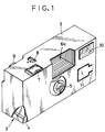
- a lens-fitted film unit 2 consists of a film housing 3 having a photograph taking mechanism and an external casing 4 for containing the film housing 3. Photographs are taken with the film housing 3 contained in the external casing 4.
- the external casing 4 is provided so that the lens-fitted film unit 2 looks agreeable, and is for example a paper box with the exterior surface printed.
- the external casing 4 has openings for exposing a taking lens 5, an object-side finder window 6a, an eye-side finder window 6b (see Fig. 2), a shutter release button 7, a film counter 8, a film advancing knob 9 and a light emitting section 10 containing a flash tube, and a cutting 11 for being pushed to operate a flash switch (not shown) easily.
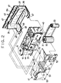
- the film housing 2 comprises a main body 40, a front cover 41 to be arranged in front thereof, and a rear cover 42 to be arranged behind the main body 4 after loading photographic film.
- the main body 40, the front cover 41 and the rear cover 42 are molded from plastics each integratedly.
- the main body 40 is provided with mechanisms necessary for taking a photograph, i.e. the taking lens 5, the film counter 8, a shutter mechanism 12, a film wind-up mechanism and an electronic flash device 43.
- Holes 44 are provided with the front side of the main body 40 for positioning it with respect to the front cover 41.
- the main body 40 is provided with a film take-up chamber 29 for containing a cassette body 32 of a 35 mm film cassette, a film supplying chamber 28 for containing a roll of unexposed film 30 e.g. negative film, and an exposure station defined between the two chambers 28 and 29. It is noted that a rotatable spool may be provided in the film supplying chamber 28, and that the roll of film 30 may be wound around it.
- the unexposed film 30 is contained in the cassette body 32 with a film trailer attached to a spool 31 of the cassette.
- the unexposed film 30 is drawn out of the cassette body 32 and wound in a roll.
- a plurality of arresting claws 47 and 48 are formed on the rear cover 42 on the top and the bottom for attaching the rear cover 42 to the front cover 41.
- a bottom surface 49 provided with the arresting claws 48 is in the shape of a lid downward openable so as to unload the cassette therefrom after completing exposure.
- Reference numerals 35 and 36 designate projections to be fitted on the chambers 28 and 29 in order to position the main body 40 on the rear cover 42.
- a groove 37 is formed around the projections 35 and 36 to be fitted on a ridge (not shown) formed behind the main body 40. The groove 37 with the ridge fitted therein forms a labyrinth seal to shield the two chambers 28 and 29 from light.
- An opening 50 is formed on the front cover 41 through which the taking lens 5 is directed to a view field.
- the rear surface of the front cover 41 around the opening 50 is provided with pins 51 to be fitted in the holes 44 of the main body 40.
- Arresting holes 52 and 53 are formed on the rear cover 41 on the top and the bottom in the positions corresponding to the arresting claws 47 and 48 formed on the rear cover 42. The arrest between the claws 47 and 48 and the holes 52 and 53 causes the front and rear covers 41 and 42 to hold the main body 40 fixedly therebetween in a fixed state.
- the main body 40 can be removed by disengaging the claws 47 and 48 without damaging the main body 4 when the used film cassette submitted to a laboratory is disassembled by applying a tool or a jig.
- a tool or a jig In order to disengage the claws 47 and 48 with ease, it is possible as disclosed in a prior Japanese application filed by the same applicant to apply a construction of forming a slit around the claws for making it easy to deform the claws in the disengaging direction.
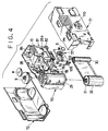
- FIG. 3 Another preferred embodiment of the inventive lens-fitted film unit is now described referring to Fig. 3.
- a rear cover 62 is attached to a film holder 61 including the two chambers 28 and 29, whereas a light-shielding tube 65 or exposure tunnel 65 is incorporated in a photo-taking device section 60, which is provided with the taking lens 5, the shutter mechanism 12 and the electronic flash device 43.
- a film containing unit 67 has the film holder 61 fixed on the rear cover 62 either by adhesion or by an arrest between claws and holes, is loaded with the unexposed film 30 therein, and has the film advancing knob 9 on the top of the film take-up chamber 29.
- An exposure station 63 is formed between the two chambers 28 and 29, and is provided with a peripheral groove 64 around it to be fitted on a rear peripheral edge 66 defined by the light-shielding tube 65.
- Insertion of the rear edge 66 in the peripheral groove 64 positions the film containing unit 67 on the photo-taking device section 60, whereas the inside of the exposure station 63 is shielded from light.
- the front cover 41 is positioned on the photo-taking device section 60 by inserting the pins 51 in the holes 44 in a manner similar to the embodiment illustrated in Fig. 2.
- the claws 47 and 48 formed on the rear cover 62 arrest the holes 52 and 53 formed on the front cover 41 to finish the assembly of the film housing 2.
- the film housing 2 consists of a main body 70, a front cover 71 and a rear cover 72 both attached to the main body 70 by use of claws, which covers are molded from plastics of a light-shielding characteristic each integratedly.
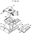
- the front side of the film supplying chamber 28 is provided with an arresting claw 28a for supporting a printed-circuit board later to be described.
- a lens board 77 for holding the taking lens 5 is mounted on a light-shielding tube 78, which is formed between the two chambers 28 and 29.
- a shutter blade 79 is provided on the front side of the light-shielding tube 78, biassed by a spring 79a, and covers an opening 80, indicated by the broken line, except for the photo-taking time for exposure.
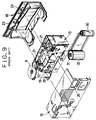
- a printed-circuit board 81 holding the light emitting section 10 is mounted on the right side of the light-shielding tube 78.
- a circuit pattern 82 is printed on the front surface of the printed-circuit board 81, to whose rear surface there are connected a terminal 83 for contact with a negative terminal of a battery and a capacitor 84. The circuit pattern 82 together with the capacitor 84 constitutes the electronic flash circuit 43.
- the supporting plate 90 and the supporting members 91 define a thin spacing therebetween in which the printed-circuit board 81 is inserted in the direction indicated by the arrow.
- the supporting plate 90 is provided with a pair of projections 92 for positioning the printed-circuit board 81 and an arresting hole 93 for positioning and supporting the lens board 77 on the light-shielding tube 78 by arresting a claw 101 of the lens board 77 later to be described.
- the projections 82 may be formed on the back surface of the supporting members 91 instead of the supporting plate 90.
- the construction of supporting the printed-circuit board 81 is not limited by the description herein, to which variations may be made.
- the circuit pattern 82 has lands 97 and 98 to be connected to the X contact.
- the lens board 77 is provided with a pair of recesses 100 and the arresting claw 101 formed thereon.
- the recesses 100 are fitted on the supporting members 91 to position the lens board 77.
- a pair of metal plates 102 and 103 constituting the above X contact are mounted on the lens board 77.
- Five ridges 77a to 77e are formed on the lens board 77.
- the ridges 77b, 77c and 77e are in contact with the metal plate 102 whereas the ridges 77a, 77b and 77d are in contact with the metal plate 103, which metal plates are kept in parallel thereby.
- a reference numeral 76 designates an opening for passing light coming through the taking lens 5.
- Ends of the metal plates 102 and 103 are bent vertically in the shape of a letter L along the widthwise direction, and form contact portions 102a and 103a to be in contact with the lands 97 and 98 as illustrated in Fig. 7.
- Middles 102b and 103b of the contact portions 102a and 103a project downward as compared with both lateral sides of the contact portions 102a and 103a, and are located to be lower than the upper surface of the printed-circuit board 81.
- Inclined surfaces 104 are formed to be connected to the middles 102b and 103b.
- the advancing edge of the printed-circuit board 81 is in contact with the inclined surfaces 104 to advance to the position under the contact portions 102a and 103a. Therefore, the contact portions 102a and 103a press the lands 97 and 98 in contact.
- the other end of the metal plate 103 is provided with a bent portion 103c, which is in contact with the metal plate 102 when the metal plate 103 is pressed by the shutter blade 79.
- the other end of the metal plate 102 is provided with a terminal 105 to be in contact with a positive terminal of the battery.
- the main body 70 is assembled by mounting the lens board 77 with the metal plates 102 and 103 on the light-shielding tube 78, whereas the light emitting section 10 is mounted on the printed-circuit board 81.
- the printed-circuit board 81 is mounted on the main body 70 after assembling the main body 70 and the printed-circuit board 81.
- the printed-circuit board 81 is slid on the supporting plate 90 in the direction of the arrow so as to insert the advancing end between the supporting plate 90 and the supporting members 91.
- the advancing end of the printed-circuit board 81 presses the contact portions 102a and 103a upward by contact with the inclined surfaces 104.
- a further slide brings the printed-circuit board 81 in contact with the projections 92.
- the printed-circuit board 81 is curved slightly in the shape of a letter U, and inserted by keeping the curved state until the advancing end is in contact with the light-shielding tube 78.
- the printed-circuit board 81 When the printed-circuit board 81 is released from the deforming force, the printed-circuit board 81 becomes plane so that the holes 95 are fitted on the projections 92 with the printed-circuit board 81 supported and positioned on the light-shielding tube 78. Because the lens board 77 is positioned on the light-shielding tube 78, the contact portions 102a and 103a are kept in reliable contact with the lands 97 and 98.
- both lateral edges of the printed-circuit board 81 are upward raised by deformation to release the projections 92 from the holes 95 so that the printed-circuit board 81 becomes slidable in the direction toward the right in Fig. 5.
- a slide of the printed-circuit board 81 releases its attachment to the light-shielding tube 78 with the metal plates 102 and 103 left on the main body 70.
- Fig. 8 illustrates a further preferred embodiment in which the contact portions 102a and 103a of the X contact are pressed with an additional pressure on the printed-circuit board 81 so as to improve the connection of the metal plates and the electronic flash circuit.
- the construction illustrated in Fig. 8 is of pressing one of the two contact portions, while both of the contact portions 102a and 103a are actually pressed.
- the printed-circuit board 81 is similarly mounted on the front side of the supporting plate 90.
- the metal plate 102 arranged on the front side of the printed-circuit board 81 is pressed by a projection 110 formed on the front cover 71, and held between the projection 110 and the land 97.
- the projection 110 is provided with a groove 112, which has guide surfaces 111, which correct the position of the metal plate 102 when the metal plate 102 is deviated in position.
- the top of the projection 110 is in contact with the metal plate 102. Even if the position of the metal plate 102 is deviated upward or downward, it is appropriately inserted in the groove 112 by assistance of the guide surfaces 111.
- the groove 112 presses the metal plate 102 to the right in Fig. 8 against the printed-circuit board 81.
- the contact portion 102a is pressed against the land 97 in a reliable contact.
- the front cover and the rear cover may be attached together by use of ultrasonic welding instead of arresting claws in holes in the same positions of the arrest.
- a lens-fitted photographic film unit according to the present invention may have a construction of requiring no cassette or containing two cassettes respectively in the film supplying chamber and the film take-up chamber.
- the above-described film housing in the inventive film unit consists of three components i.e. the front cover, the rear cover and the main body, it may consists of four components including an upper cover separated from the above front cover, so that each of the front and rear covers is attached to the upper cover so as to support the main body by/between the front and rear covers.
Landscapes
- Physics & Mathematics (AREA)
- General Physics & Mathematics (AREA)
- Structure And Mechanism Of Cameras (AREA)
- Camera Bodies And Camera Details Or Accessories (AREA)
Applications Claiming Priority (4)
| Application Number | Priority Date | Filing Date | Title |
|---|---|---|---|
| JP180994/90 | 1990-07-09 | ||
| JP18099490 | 1990-07-09 | ||
| JP83580/90U | 1990-08-07 | ||
| JP8358090 | 1990-08-07 |
Publications (3)
| Publication Number | Publication Date |
|---|---|
| EP0465897A2 true EP0465897A2 (fr) | 1992-01-15 |
| EP0465897A3 EP0465897A3 (en) | 1993-03-10 |
| EP0465897B1 EP0465897B1 (fr) | 1997-09-10 |
Family
ID=26424621
Family Applications (1)
| Application Number | Title | Priority Date | Filing Date |
|---|---|---|---|
| EP91110289A Expired - Lifetime EP0465897B1 (fr) | 1990-07-09 | 1991-06-21 | Corps principal d'une caméra muni d'un objectif |
Country Status (5)
| Country | Link |
|---|---|
| US (1) | US5170199A (fr) |
| EP (1) | EP0465897B1 (fr) |
| KR (1) | KR0154986B1 (fr) |
| CN (1) | CN1031478C (fr) |
| DE (1) | DE69127594T2 (fr) |
Cited By (5)
| Publication number | Priority date | Publication date | Assignee | Title |
|---|---|---|---|---|
| EP0560101A1 (fr) * | 1992-03-09 | 1993-09-15 | Eastman Kodak Company | Emballage de film photographique et caméra à usage unique |
| EP0596509A1 (fr) * | 1992-11-04 | 1994-05-11 | Fuji Photo Film Co., Ltd. | Méthode et dispositif de démontage et de montage d'un article |
| US5452033A (en) * | 1994-06-06 | 1995-09-19 | Eastman Kodak Company | Single use photographic film package and camera |
| EP0679929A1 (fr) * | 1994-04-28 | 1995-11-02 | Agfa-Gevaert AG | Emballage de film photographique avec une lentille d'objectif |
| DE4223117B4 (de) * | 1991-07-15 | 2006-11-30 | Fuji Photo Film Co., Ltd., Minami-Ashigara | Einwegkamera |
Families Citing this family (14)
| Publication number | Priority date | Publication date | Assignee | Title |
|---|---|---|---|---|
| US5368664A (en) * | 1991-11-01 | 1994-11-29 | Fuji Photo Film Co., Ltd. | Photographic film cassette and method of manufacturing the same |
| EP0565097B1 (fr) * | 1992-04-09 | 1997-07-02 | Fuji Photo Film Co., Ltd. | Emballage de film photographique muni d'un objectif |
| US5600391A (en) * | 1992-09-15 | 1997-02-04 | Eastman Kodak Company | One piece viewfinder and fabrication process |
| EP0599230B1 (fr) * | 1992-11-20 | 1998-02-04 | Fuji Photo Film Co., Ltd. | Méthode et dispositif de démontage d'une unité de film |
| US5615394A (en) * | 1994-06-23 | 1997-03-25 | Eastman Kodak Company | Anamorphic lens for a photographic flash assembly |
| US5574337A (en) * | 1994-06-30 | 1996-11-12 | Eastman Kodak Company | Single touch flash charger control |
| US5541687A (en) * | 1995-01-03 | 1996-07-30 | Eastman Kodak Company | Electronic flash assemblage with reflector to circuit board connection |
| US5870643A (en) * | 1995-12-28 | 1999-02-09 | Eastman Kodak Company | Single-use flash cameras with reflector or siren |
| GB2312050B (en) * | 1996-04-10 | 2001-04-04 | Eastman Kodak Co | Camera with smile sound |
| US5878283A (en) * | 1996-09-05 | 1999-03-02 | Eastman Kodak Company | Single-use camera with motion sensor |
| US5708876A (en) * | 1997-01-14 | 1998-01-13 | Eastman Kodak Company | One-time-use camera with combined shutter-flash synchronization contact and holder for flash capacitor and battery |
| US7126629B1 (en) | 2001-09-07 | 2006-10-24 | Pure Digital Technologies, Icn. | Recyclable, digital one time use camera |
| US6628896B2 (en) | 2001-12-04 | 2003-09-30 | Arc Design, Inc. | Motorized single use camera |
| EP1722681A4 (fr) * | 2004-03-06 | 2010-03-03 | Calisto Medical Inc | Procedes et dispositifs de mesure non invasive de donnees de quantitatives de substances d'organismes vivants |
Family Cites Families (6)
| Publication number | Priority date | Publication date | Assignee | Title |
|---|---|---|---|---|
| JPS4957833A (fr) * | 1972-09-30 | 1974-06-05 | ||
| US4041507A (en) * | 1975-07-02 | 1977-08-09 | W. Haking Industries, Ltd. | Camera for underwater and above water use |
| US4803504A (en) * | 1984-09-03 | 1989-02-07 | Canon Kabushiki Kaisha | Waterproof camera |
| US4801957A (en) * | 1988-02-18 | 1989-01-31 | Eastman Kodak Company | Disposable single-use camera and accessory re-usable electronic flash unit |
| DE3905310C2 (de) * | 1988-02-22 | 2003-02-27 | Fuji Photo Film Co Ltd | Einwegkamera |
| US4882600A (en) * | 1989-04-07 | 1989-11-21 | Eastman Kodak Company | Underwater disposable single-use camera |
-
1991
- 1991-06-21 DE DE69127594T patent/DE69127594T2/de not_active Expired - Fee Related
- 1991-06-21 EP EP91110289A patent/EP0465897B1/fr not_active Expired - Lifetime
- 1991-07-08 KR KR1019910011516A patent/KR0154986B1/ko not_active Expired - Fee Related
- 1991-07-08 CN CN91104519A patent/CN1031478C/zh not_active Expired - Fee Related
- 1991-07-09 US US07/727,243 patent/US5170199A/en not_active Expired - Lifetime
Cited By (7)
| Publication number | Priority date | Publication date | Assignee | Title |
|---|---|---|---|---|
| DE4223117B4 (de) * | 1991-07-15 | 2006-11-30 | Fuji Photo Film Co., Ltd., Minami-Ashigara | Einwegkamera |
| EP0560101A1 (fr) * | 1992-03-09 | 1993-09-15 | Eastman Kodak Company | Emballage de film photographique et caméra à usage unique |
| EP0596509A1 (fr) * | 1992-11-04 | 1994-05-11 | Fuji Photo Film Co., Ltd. | Méthode et dispositif de démontage et de montage d'un article |
| US5377399A (en) * | 1992-11-04 | 1995-01-03 | Fuji Photo Film Co., Ltd. | Method and apparatus for disassembling and reassembling an article |
| EP0679929A1 (fr) * | 1994-04-28 | 1995-11-02 | Agfa-Gevaert AG | Emballage de film photographique avec une lentille d'objectif |
| US5864717A (en) * | 1994-04-28 | 1999-01-26 | Agfa-Gevaert Ag | Photographic roll-film pack with a picture-taking lens |
| US5452033A (en) * | 1994-06-06 | 1995-09-19 | Eastman Kodak Company | Single use photographic film package and camera |
Also Published As
| Publication number | Publication date |
|---|---|
| KR0154986B1 (ko) | 1998-12-01 |
| KR920003095A (ko) | 1992-02-29 |
| US5170199A (en) | 1992-12-08 |
| CN1031478C (zh) | 1996-04-03 |
| DE69127594T2 (de) | 1998-01-22 |
| DE69127594D1 (de) | 1997-10-16 |
| EP0465897A3 (en) | 1993-03-10 |
| EP0465897B1 (fr) | 1997-09-10 |
| CN1058106A (zh) | 1992-01-22 |
Similar Documents
| Publication | Publication Date | Title |
|---|---|---|
| EP0465897B1 (fr) | Corps principal d'une caméra muni d'un objectif | |
| US5436685A (en) | Lens-fitted photographic film unit whose parts can be recycled easily | |
| US5235364A (en) | Lens-fitted photographic film package with flash unit | |
| US5126775A (en) | Lens-fitted photographic film package and method of film reloading therefor | |
| US4896178A (en) | Lens-fitted photographic film unit | |
| US5608486A (en) | Lens-fitted photographic film package | |
| GB2216278A (en) | Lens-fitted photographic film package | |
| US4766451A (en) | Photographic film package | |
| US3852780A (en) | Film pack adapter | |
| KR100570311B1 (ko) | 컴팩트 카메라 | |
| EP0527430B1 (fr) | Emballage de film photographique muni d'un objectif | |
| US5555062A (en) | Recyclable single-use camera with replaceable front lens element | |
| JP2942647B2 (ja) | レンズ付きフイルムユニット | |
| US6542701B2 (en) | Camera | |
| US6480682B1 (en) | Photometric device comprising a photo sensor mounted on a circuit board | |
| JP3310770B2 (ja) | レンズ付きフイルムユニット及びその製造方法 | |
| US6356711B1 (en) | Lens-fitted photo film unit and sprocket wheel for the same | |
| JP2847901B2 (ja) | 特殊画面撮影用の遮光部材および撮影範囲表示部材 | |
| GB2247755A (en) | Lens-fitted photographic film package | |
| JPS6148822A (ja) | フイルムパツクアダプタ | |
| KR100665725B1 (ko) | 보조 모듈을 갖는 렌즈 부착 사진 필름 유닛 | |
| JP2000066276A (ja) | レンズ付きフイルムユニット | |
| JPH0643591A (ja) | レンズ付きフイルムユニット | |
| JP2002344171A (ja) | 金属接片の取り付け構造 | |
| JPH0715545B2 (ja) | レンズ付きフイルムユニット |
Legal Events
| Date | Code | Title | Description |
|---|---|---|---|
| PUAI | Public reference made under article 153(3) epc to a published international application that has entered the european phase |
Free format text: ORIGINAL CODE: 0009012 |
|
| AK | Designated contracting states |
Kind code of ref document: A2 Designated state(s): DE FR GB |
|
| PUAL | Search report despatched |
Free format text: ORIGINAL CODE: 0009013 |
|
| AK | Designated contracting states |
Kind code of ref document: A3 Designated state(s): DE FR GB |
|
| 17P | Request for examination filed |
Effective date: 19930615 |
|
| 17Q | First examination report despatched |
Effective date: 19950320 |
|
| GRAG | Despatch of communication of intention to grant |
Free format text: ORIGINAL CODE: EPIDOS AGRA |
|
| GRAH | Despatch of communication of intention to grant a patent |
Free format text: ORIGINAL CODE: EPIDOS IGRA |
|
| GRAH | Despatch of communication of intention to grant a patent |
Free format text: ORIGINAL CODE: EPIDOS IGRA |
|
| GRAA | (expected) grant |
Free format text: ORIGINAL CODE: 0009210 |
|
| AK | Designated contracting states |
Kind code of ref document: B1 Designated state(s): DE FR GB |
|
| REF | Corresponds to: |
Ref document number: 69127594 Country of ref document: DE Date of ref document: 19971016 |
|
| ET | Fr: translation filed | ||
| PLBE | No opposition filed within time limit |
Free format text: ORIGINAL CODE: 0009261 |
|
| STAA | Information on the status of an ep patent application or granted ep patent |
Free format text: STATUS: NO OPPOSITION FILED WITHIN TIME LIMIT |
|
| 26N | No opposition filed | ||
| REG | Reference to a national code |
Ref country code: GB Ref legal event code: IF02 |
|
| REG | Reference to a national code |
Ref country code: FR Ref legal event code: CD Ref country code: FR Ref legal event code: TP |
|
| PGFP | Annual fee paid to national office [announced via postgrant information from national office to epo] |
Ref country code: DE Payment date: 20080626 Year of fee payment: 18 |
|
| PGFP | Annual fee paid to national office [announced via postgrant information from national office to epo] |
Ref country code: FR Payment date: 20080617 Year of fee payment: 18 |
|
| PGFP | Annual fee paid to national office [announced via postgrant information from national office to epo] |
Ref country code: GB Payment date: 20080625 Year of fee payment: 18 |
|
| GBPC | Gb: european patent ceased through non-payment of renewal fee |
Effective date: 20090621 |
|
| REG | Reference to a national code |
Ref country code: FR Ref legal event code: ST Effective date: 20100226 |
|
| PG25 | Lapsed in a contracting state [announced via postgrant information from national office to epo] |
Ref country code: FR Free format text: LAPSE BECAUSE OF NON-PAYMENT OF DUE FEES Effective date: 20090630 |
|
| PG25 | Lapsed in a contracting state [announced via postgrant information from national office to epo] |
Ref country code: GB Free format text: LAPSE BECAUSE OF NON-PAYMENT OF DUE FEES Effective date: 20090621 |
|
| PG25 | Lapsed in a contracting state [announced via postgrant information from national office to epo] |
Ref country code: DE Free format text: LAPSE BECAUSE OF NON-PAYMENT OF DUE FEES Effective date: 20100101 |