EP0465902A2 - Enceinte acoustique intégré de télévision - Google Patents
Enceinte acoustique intégré de télévision Download PDFInfo
- Publication number
- EP0465902A2 EP0465902A2 EP91110339A EP91110339A EP0465902A2 EP 0465902 A2 EP0465902 A2 EP 0465902A2 EP 91110339 A EP91110339 A EP 91110339A EP 91110339 A EP91110339 A EP 91110339A EP 0465902 A2 EP0465902 A2 EP 0465902A2
- Authority
- EP
- European Patent Office
- Prior art keywords
- housing
- bass
- loudspeaker
- mid
- sound pressure
- Prior art date
- Legal status (The legal status is an assumption and is not a legal conclusion. Google has not performed a legal analysis and makes no representation as to the accuracy of the status listed.)
- Withdrawn
Links
- 230000011514 reflex Effects 0.000 claims abstract description 9
- 238000001816 cooling Methods 0.000 claims abstract description 7
- 238000011161 development Methods 0.000 description 1
- 230000018109 developmental process Effects 0.000 description 1
Images
Classifications
-
- H—ELECTRICITY
- H04—ELECTRIC COMMUNICATION TECHNIQUE
- H04N—PICTORIAL COMMUNICATION, e.g. TELEVISION
- H04N5/00—Details of television systems
- H04N5/64—Constructional details of receivers, e.g. cabinets or dust covers
- H04N5/642—Disposition of sound reproducers
Definitions
- the invention relates to the loudspeaker arrangement, in particular of bass loudspeakers in television sets.
- Speakers are conventionally integrated in television sets in the front of the device or in the side of the device.
- this requires front surface cross sections which are relatively large in size in comparison to television sets whose loudspeakers are embedded in the side surfaces of the device.
- the latter applies in particular if, in addition to, for example, tweeters and midrange speakers, bass speakers are also to be used for improved sound reproduction. This is based on the fact that for a good bass reproduction the bass speakers require much larger cross-sections in comparison to the tweeters and mid-range speakers as well as to the mid-high speakers.
- the invention has for its object to provide a bass speaker assembly for televisions that do not require larger opening cross-sections in the front face of the device than tweeters and midrange speakers or mid-high speakers in large-dimension bass speakers and thus the guaranteed good sound behavior.
- bass speakers are inserted into an external opening of the speaker housing pointing towards the inside of the device, so that part of the sound pressure generated by the bass speaker through a bass reflex tube on the front and the other part of the sound pressure inside the device through the cooling openings in the screen are arranged facing away from the housing, is emitted and contributes to the diffuse sound field.
- the opening cross sections of the bass reflex tubes are made smaller / equal to the opening cross sections for the other speakers, very narrow side areas or head or bottom areas can be formed without the sound quality of the bass reproduction being reduced as a result. If, as claimed in claim 3, the outer openings in the loudspeaker housings either face the picture tube or the rear wall of the device housing, the bass loudspeakers used in these outer openings of the loudspeaker housing show their best sound behavior.
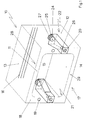
- Figure 1 shows a housing of a television set in perspective.
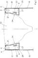
- Figure 2 shows a sectional view through a housing of a television set.
- FIG 1 is a device housing 10 of a television set shown.
- This device housing 10 is formed by the device front surface 11, the two device side surfaces 12, the roof surface 13 and the floor 14 and the rear front 15.
- the rear front 15 is provided with cooling openings 16.
- the cooling openings 16 can also be arranged in the roof surface 13 and in the device side surfaces 12.
- the front face 11 of the device has two openings 19, 20, one above the other, in the two side regions 18 of the front face 11 of the device.
- the openings 19 are provided for receiving mid-range speakers. When using tweeters and mid-range speakers, the openings 19 per side area 18 must be doubled.
- the loudspeaker housings 22 are attached to the rear 21 of the front face 11 of the device in the area of the openings 20, the sides of the loudspeaker housings 22 directly pointing to the front face 11 of the device and the side faces 12 of the device being formed by the front face 11 of the device and the respective side faces 12 of the device.
- the mutually facing surfaces of the two loudspeaker housings 22 run parallel to one another in the front region close to the device front surface 11 and then taper towards one another. This design of the loudspeaker housing 22 was therefore chosen in order to optimally use the space formed for the respective device side surface 12 when the picture tube is inserted, but not shown in this figure.
- any other shape of the loudspeaker housing 22 is also possible, provided that it is ensured that at least one of the housing surfaces of the loudspeaker housing 22 is designed such that it is sufficiently large for the interior of the device indicative outer opening 24 into which the bass speaker can be inserted. 1, these outer openings 24 are arranged on the side of the loudspeaker housing 22 facing the rear front 15 of the device housing 10, in FIG. 2 these outer openings 24 are located on the surface of the loudspeaker housing 22 which lies opposite the picture tube 22.
- the bass reflex tubes 26 are inserted at the openings 20, which - as is particularly emphasized in FIG. 1 - have the same opening cross section as the openings 19 and are guided into the loudspeaker housing 22.
- the bass loudspeakers 25 are inserted into the outer openings 24 of the loudspeaker housing 22, the voice coils 27 lying outside in FIG. 1 and inside the loudspeaker housing 22 in FIG. 2.
- the use of the bass loudspeaker 25 in the outer openings 24 ensures that the sound pressure emitted by the respective bass loudspeaker 25 is partly radiated through the bass reflex tube 26 at the front and partly through the cooling openings 16.
- the loudspeaker housing 22 can be equipped with materials (not shown) for influencing the sound.
- FIG. 2 which shows a section through a device housing 10 of a television set in the area of the loudspeaker housings 22, illustrates that the loudspeaker housings 22 adjacent to the picture tube 23 are partly formed by the front surface 11 and the side surfaces 12 of the device.
- the remaining part of the speaker housing 22 is formed as a molded part and on the edges K with the back 21 of the front face 11 and the Device housing side surfaces 12 glued.
- the molded part can also be fastened to the device front surface 11 and the device side surface 12 in a different manner, for example by screwing or clamping.
- the area of application of the loudspeaker boxes is not limited to the side areas 18 of the front face of the device. Rather, applications are also possible in which the loudspeaker housing 22 is arranged between the roof surface 13 and the picture tube 23 and the floor 14 and the picture tube 23. In the case of mono television sets, the application of the arrangement according to the invention can be restricted to a side area 18 and the head or bottom area 28, 29.
- loudspeaker housings 22 are not at least partially formed by the device housing 10, as shown in the figures, these loudspeaker housings 22 can be inserted and connected very quickly as a compact component in the device housing 10.
- the disadvantage here is the fact that the space between the picture tube 23 and the respective device side surface 12 is reduced by the thickness of the speaker wall pointing towards the device side surface.
Landscapes
- Engineering & Computer Science (AREA)
- Multimedia (AREA)
- Signal Processing (AREA)
- Details Of Audible-Bandwidth Transducers (AREA)
Applications Claiming Priority (2)
| Application Number | Priority Date | Filing Date | Title |
|---|---|---|---|
| DE4022370 | 1990-07-13 | ||
| DE19904022370 DE4022370A1 (de) | 1990-07-13 | 1990-07-13 | Integrierte fernsehlautsprecherbox |
Publications (2)
| Publication Number | Publication Date |
|---|---|
| EP0465902A2 true EP0465902A2 (fr) | 1992-01-15 |
| EP0465902A3 EP0465902A3 (en) | 1992-04-22 |
Family
ID=6410240
Family Applications (1)
| Application Number | Title | Priority Date | Filing Date |
|---|---|---|---|
| EP19910110339 Withdrawn EP0465902A3 (en) | 1990-07-13 | 1991-06-22 | Integrated television loudspeaker box |
Country Status (2)
| Country | Link |
|---|---|
| EP (1) | EP0465902A3 (fr) |
| DE (1) | DE4022370A1 (fr) |
Families Citing this family (3)
| Publication number | Priority date | Publication date | Assignee | Title |
|---|---|---|---|---|
| DE9307838U1 (de) * | 1993-05-25 | 1993-07-22 | Nokia (Deutschland) GmbH, 7530 Pforzheim | Fernsehgerät |
| DE19806509B4 (de) * | 1998-02-17 | 2007-12-13 | Harman Becker Automotive Systems Gmbh | Gerät zur Informationswiedergabe |
| CN114390402B (zh) * | 2022-01-04 | 2024-04-26 | 杭州老板电器股份有限公司 | 一种吸油烟机的音频注入控制方法、装置及吸油烟机 |
Family Cites Families (10)
| Publication number | Priority date | Publication date | Assignee | Title |
|---|---|---|---|---|
| GB624896A (en) * | 1947-02-20 | 1949-06-17 | Henry Ibbotson | Improvements in or relating to television receiving apparatus |
| DE7639267U1 (de) * | 1976-12-15 | 1977-05-12 | Graetz Gmbh & Co Ohg, 5990 Altena | Fernsehempfaengergehaeuse mit integrierter lautsprecherbox |
| DE3128462C2 (de) * | 1981-07-18 | 1983-07-07 | Standard Elektrik Lorenz Ag, 7000 Stuttgart | Fernsehempfangsgerät für stereophone Tonwiedergabe |
| DE8304832U1 (de) * | 1983-02-22 | 1983-06-09 | Deutsche Thomson-Brandt Gmbh, 7730 Villingen-Schwenningen | Fernsehgeraet mit internem tieftonlautsprecher |
| DE3405128A1 (de) * | 1984-02-14 | 1985-08-22 | Standard Elektrik Lorenz Ag, 7000 Stuttgart | Vorrichtung zur stereophonen tonwiedergabe in einem fernsehempfangsgeraet |
| FR2631195B1 (fr) * | 1988-05-06 | 1990-07-27 | Loire Electronique | Installation sonore, en particulier stereophonique pour televiseurs a haut-parleur integre de frequences basses de grandes dimensions |
| DE3819217A1 (de) * | 1988-06-06 | 1989-12-07 | Meggl Friedemann | Lautsprechersystem |
| DE3829278A1 (de) * | 1988-08-30 | 1990-03-01 | Telefunken Fernseh & Rundfunk | Lautsprecheranordnung fuer einen hdtv-fernsehempfaenger |
| DE3835539A1 (de) * | 1988-10-19 | 1990-04-26 | Thomson Brandt Gmbh | Lautsprecherbox fuer fernseh- und andere geraete |
| DE3842949A1 (de) * | 1988-12-21 | 1990-06-28 | Grundig Emv | Fernsehgeraet mit einem aus kunststoff gefertigten gehaeuse |
-
1990
- 1990-07-13 DE DE19904022370 patent/DE4022370A1/de not_active Withdrawn
-
1991
- 1991-06-22 EP EP19910110339 patent/EP0465902A3/de not_active Withdrawn
Also Published As
| Publication number | Publication date |
|---|---|
| EP0465902A3 (en) | 1992-04-22 |
| DE4022370A1 (de) | 1992-01-16 |
Similar Documents
| Publication | Publication Date | Title |
|---|---|---|
| DE4446690B4 (de) | Lautsprecheranordnung | |
| DE69431391T2 (de) | Lautsprechersystem für Fernsehgeräte | |
| DE3037496C2 (de) | Lautsprecheranlage zur Wiedergabe im Mittel- und/oder Tieftonbereich | |
| EP0480160B1 (fr) | Haut-parleur haute fréquence en forme de calotte | |
| DE68908766T2 (de) | Tonanlage, besonders zur stereophonen Tonwiedergabe in einem Fernsehempfangsgerät mit integriertem Tieftonlautsprecher grosser Dimensionen. | |
| DE8314251U1 (de) | Lautsprecherbox mit integriertem akustischem Bandpaßfilter | |
| DE3933170A1 (de) | Verfahren und vorrichtung zur stereophonen tonwiedergabe | |
| DE69110731T2 (de) | Audio- oder Videoapparat mit Einbaulautsprecher. | |
| DE69329925T2 (de) | Fernsehempfänger | |
| DE3818366A1 (de) | Lautsprecheranlage | |
| DE2839111A1 (de) | Lautsprechersystem | |
| DE3405128A1 (de) | Vorrichtung zur stereophonen tonwiedergabe in einem fernsehempfangsgeraet | |
| DE69902778T2 (de) | Lautsprecherapparat und fernsehgerät | |
| DE69430776T2 (de) | Lautsprecherapparat | |
| DE212013000301U1 (de) | Hornförmige Multipoint-Anregungslautsprecherbox | |
| DE4022370A1 (de) | Integrierte fernsehlautsprecherbox | |
| DE3144545A1 (de) | Lautsprechersystem | |
| DE102006059197A1 (de) | Ohrhörer | |
| DE202008017790U1 (de) | Lautsprecheranordnung | |
| EP0575895B1 (fr) | Arrangement de haut-parleurs pour téléspectateurs | |
| DE69125512T2 (de) | Tonausrüstung für einen Fernseher | |
| EP0372186B1 (fr) | Enceintes acoustiques pour téléviseur et autres appareils | |
| EP0692922A2 (fr) | Enceinte acoustique pour haut-parleur basse-fréquence | |
| DE3616563A1 (de) | Anordnung fuer basslautsprecher mit einem schalltrichter | |
| DE19908631C2 (de) | Anordnung von Lautsprechern zu Beschallungszwecken |
Legal Events
| Date | Code | Title | Description |
|---|---|---|---|
| PUAI | Public reference made under article 153(3) epc to a published international application that has entered the european phase |
Free format text: ORIGINAL CODE: 0009012 |
|
| AK | Designated contracting states |
Kind code of ref document: A2 Designated state(s): DE ES FR GB IT NL SE |
|
| PUAL | Search report despatched |
Free format text: ORIGINAL CODE: 0009013 |
|
| RAP1 | Party data changed (applicant data changed or rights of an application transferred) |
Owner name: NOKIA (DEUTSCHLAND) GMBH |
|
| AK | Designated contracting states |
Kind code of ref document: A3 Designated state(s): DE ES FR GB IT NL SE |
|
| 17P | Request for examination filed |
Effective date: 19920612 |
|
| 17Q | First examination report despatched |
Effective date: 19940317 |
|
| STAA | Information on the status of an ep patent application or granted ep patent |
Free format text: STATUS: THE APPLICATION IS DEEMED TO BE WITHDRAWN |
|
| 18D | Application deemed to be withdrawn |
Effective date: 19950607 |