EP0465941A2 - Torche à plasma à arc transféré - Google Patents
Torche à plasma à arc transféré Download PDFInfo
- Publication number
- EP0465941A2 EP0465941A2 EP91110640A EP91110640A EP0465941A2 EP 0465941 A2 EP0465941 A2 EP 0465941A2 EP 91110640 A EP91110640 A EP 91110640A EP 91110640 A EP91110640 A EP 91110640A EP 0465941 A2 EP0465941 A2 EP 0465941A2
- Authority
- EP
- European Patent Office
- Prior art keywords
- plasma torch
- end piece
- torch according
- jacket
- nozzle end
- Prior art date
- Legal status (The legal status is an assumption and is not a legal conclusion. Google has not performed a legal analysis and makes no representation as to the accuracy of the status listed.)
- Granted
Links
Images

Classifications
-
- H—ELECTRICITY
- H05—ELECTRIC TECHNIQUES NOT OTHERWISE PROVIDED FOR
- H05H—PLASMA TECHNIQUE; PRODUCTION OF ACCELERATED ELECTRICALLY-CHARGED PARTICLES OR OF NEUTRONS; PRODUCTION OR ACCELERATION OF NEUTRAL MOLECULAR OR ATOMIC BEAMS
- H05H1/00—Generating plasma; Handling plasma
- H05H1/24—Generating plasma
- H05H1/26—Plasma torches
- H05H1/32—Plasma torches using an arc
- H05H1/34—Details, e.g. electrodes, nozzles
- H05H1/3431—Coaxial cylindrical electrodes
-
- H—ELECTRICITY
- H05—ELECTRIC TECHNIQUES NOT OTHERWISE PROVIDED FOR
- H05H—PLASMA TECHNIQUE; PRODUCTION OF ACCELERATED ELECTRICALLY-CHARGED PARTICLES OR OF NEUTRONS; PRODUCTION OR ACCELERATION OF NEUTRAL MOLECULAR OR ATOMIC BEAMS
- H05H1/00—Generating plasma; Handling plasma
- H05H1/24—Generating plasma
- H05H1/26—Plasma torches
- H05H1/32—Plasma torches using an arc
- H05H1/34—Details, e.g. electrodes, nozzles
-
- H—ELECTRICITY
- H05—ELECTRIC TECHNIQUES NOT OTHERWISE PROVIDED FOR
- H05H—PLASMA TECHNIQUE; PRODUCTION OF ACCELERATED ELECTRICALLY-CHARGED PARTICLES OR OF NEUTRONS; PRODUCTION OR ACCELERATION OF NEUTRAL MOLECULAR OR ATOMIC BEAMS
- H05H1/00—Generating plasma; Handling plasma
- H05H1/24—Generating plasma
- H05H1/26—Plasma torches
- H05H1/28—Cooling arrangements
Definitions
- the invention relates to a plasma torch for transmitted arc with a central electrode, a concentric nozzle end piece, wherein an annular gap for the passage of plasma gas is present between the electrode and the nozzle end piece, and a concentric burner jacket with outer, middle and inner wall, between the nozzle end piece and an annular channel is present in the burner jacket, the inner wall of which is partially formed by an insulating tube that electrically separates both parts.
- Parasitic arches not only significantly impair the stability of the arc column and thus the efficiency and economy of a plasma torch or a system operated with plasma torches, they generally even lead to the complete destruction of plasma torches.
- the insulation provided in the end face of the nozzle be laid in an end groove.
- a plasma torch has also been carried out.
- the end groove is formed on the one hand by the outer wall of a nozzle socket or end piece and on the other hand by a burner jacket, the burner jacket having on its front side a flange pointing towards the axis of the burner, which offers the insulation piece lying behind a certain heat protection.
- this burner is in an atmosphere with electrically conductive particles, e.g. B. operated metal or steel dusts, the electrically conductive dusts can precipitate on the cooled insulating piece, so that an electrical bridge from the nozzle nozzle to the burner jacket form and parasitic arcs can now flow over the outer front edge of the burner jacket.
- the invention has for its object the risk of the formation of parasitic arcs, in particular when operating with alternating current, further. H. restrict with greater success.
- the annular channel between the nozzle end piece and the burner jacket is withdrawn at least up to the level of the coolant inlet and outlet of the burner jacket and has a line connection at its rear end with a source of a pressurized gaseous medium. Due to its length, the coaxial ring channel already represents a factor that increases the operational safety and service life, because of the lack of mechanical connections on which electrically conductive vapors or dusts could be deposited, which could lead to bridges between the nozzle socket and the nozzle jacket.
- the line connection to a source of a pressurized gaseous medium is equivalent to blowing a gaseous pressure medium into the ring channel.
- Blowing the ring channel with gas represents a further step in the direction of increasing operational safety and increasing the service life.
- the mouth or outlet area of the ring channel is additionally cooled by the gas. Any electrically conductive vapors or dusts that occur are prevented from entering the ring channel. Flashback plasma arc curls are prevented and melt and slag splashes that want to penetrate into the ring channel are rejected and cooled.
- oxidation-promoting gases are shielded, which are sucked in from the environment via the plasma arc and have a strong wear-promoting effect on refractory metals that are located outside the plasma gas area.
- the plasma torch is advantageously also suitable for transporting or carrying solid substances in powder or grain form by the additional gas.
- the entire plasma arc circumference and a certain distance in the direction of the plasma arc axis can be used for melting or evaporating the solid materials in the plasma torch according to the invention.
- the homogenization of the gas flow through the ring channel can be further improved in that the line connection has a tangential component at the rear end of the ring channel.
- the line connection has a tangential component at the rear end of the ring channel.
- the at least partially tangential direction of insertion into the ring channel and the leveling that can be achieved with it is particularly important in the case of the conveyance of solids.
- the electrode and the nozzle end piece require only a low coolant throughput, it is advantageous to assign a separate cooling circuit to the burner jacket so that the required coolant throughput can be adapted to the respective degree of stress.
- the nozzle jacket is connected to the jacket tube of the burner jacket via a simple threaded connection, possibly via a connecting part. It is therefore easy to remove and thus enables the electrode and the nozzle or the nozzle end piece to be exchanged quickly for other applications, which can also be easily assembled or exchanged by means of threaded connections.
- the annular channel in its mouth region is advantageously designed to be conically converging in the direction of the arc.
- the insulating tube electrically separating the nozzle end piece and the burner jacket is adjacent to the outside of the nozzle end piece. It is also used to form the conical inner surface in the mouth region of the ring channel.
- the surfaces of the conical mouth region of the ring channel can preferably have a coating of insulation material, in particular ceramic, which makes it possible to convey electrically conductive solids through the ring channel and to feed them to the arc.
- insulation material in particular ceramic
- the insulating tube surrounding the electrode lance is further set back into the ring channel up to the line connection.
- the clear diameter of the outer edge of the ring channel at the mouth is preferably smaller than the outer diameter of the inner wall of the ring channel before the conical course begins.
- the nozzle end piece is advantageously mechanically connected to the electrode via an annular body made of insulation material and combined with it to form a structural unit.
- This annular body has passages running parallel to the main axis of the plasma torch, through which the main plasma gas can reach the annular gap between the electrode and the nozzle end piece.
- a common coolant circuit is provided for the latter.
- displacement bodies can be arranged in the ring channel.
- spacers or supporting bodies are advantageously inserted into the ring channel.
- These support bodies are shaped as aerodynamically as possible, viewed in the longitudinal axis of the burner, offset from one another and advantageously fastened to the insulating tube assigned to the electrode and the nozzle end piece.
- the support bodies can be designed as hollow and solid bodies and run axially parallel or helically and thus make a contribution to the conveyance and guidance of additives in the ring channel.
- Hollow bodies parallel to the axis can be preferred be extended as a nozzle-shaped ceramic tube beyond the end face of the nozzle end piece, for example to supply powder locally and in a directed manner to the plasma arc.
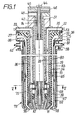
- the plasma torch essentially consists of an electrode lance and a torch jacket.
- the electrode lance again consists essentially of an electrode 10 and a nozzle nozzle or nozzle end piece 11 and the parts holding them.
- the electrode 10 has a weakly conical end surface and the nozzle nozzle 11 has a weakly conical inner surface and a more conical outer surface.
- the electrode 10 is fastened with its outer wall via a substantially sleeve-shaped connecting piece 12 to the current tube 13, a tube connected to the main voltage source, with a threaded connection or pairing in each case between the electrode 10 and the connecting piece 12 and between this and the current tube 13 consists.
- the inner wall of the electrode 10 is slidably guided on an inner tube 14 fastened in the rear end of the plasma torch. Between the flow tube 13 and the inner tube 14 there is a plastic center tube 15 for separating the partial circuits of the coolant for the electrode. In its lower area, the central tube 15 also serves to deflect the coolant flow.
- the inner wall of the nozzle end piece 11 is connected via a threaded connection to an annular body 16 made of insulation material, preferably ceramic, and this in turn is connected to the connecting piece 12 via a threaded connection.
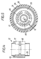
- the connecting piece 12 (cf. FIGS. 4 and 5) has upper and lower radial passages 17, 18 and passages 19 running parallel to the burner axis, distributed uniformly around its circumference.
- the passages 26 point downward into the annular gap 27 between the electrode 10 and the nozzle end piece 11.
- a plastic tube 28 Arranged around the flow tube 13 is a plastic tube 28 which has passages 29 running parallel to the axis of the burner, which pass into an annular cavity 31 in the lower region of the tube 28, which creates a connection to the passages 19 of the connecting piece 16.
- the tube 28 At its upper end, the tube 28 is provided with a flange 32 which has radial passages 33 which are connected to the axially parallel passages 29.
- the plastic tube 28 is surrounded by a steel tube 34 with a flange 35.
- the outside diameter of the steel tube 34 corresponds to the outside diameter of the nozzle end piece 11.
- An insulation tube 36 is arranged on the outside of the steel tube 34 and has a flange 37 at its upper end.
- a transition surface 38 is provided between the cylindrical outer surface of the insulation tube 36 and the underside of the flange 37.
- Another lower ceramic tube 39 lies with its inner surface on the outer surfaces of the steel tube 34 and the nozzle end piece 11 and is detachably connected to the upper insulation tube 36 via a screw or threaded connection. At its lower end, the outer surface of the lower ceramic tube 39 is continuously transferred into the conical outer surface of the nozzle end piece 11.
- An auxiliary electrode 42 is guided through the inner tube 14 of the electrode lance and is centered in a known manner by spacers. At its upper end, the auxiliary electrode 42 has a current connection 44 for the ignition current. In its upper region, the auxiliary electrode 42 is electrically separated from the inner tube 14 and the other parts of the electrode lance by a plastic disk 45.
- the plastic disk 45 has one or more radial passages 46 for supplying ignition gas, which can continue to flow through the annular channel formed by the ignition electrode 42 and the inner tube 14.
- the electrode 10 and the nozzle end piece 11 are cooled by a common, combined coolant circuit. From the coolant inlet 48, the coolant passes through the annular channel 49 formed by the inner tube 14 and the middle tube 15, is deflected at the bottom of the middle tube 15, flows through the radial passages 18, is deflected by the deflecting part 24 and flows through the passages 17 and through the flow tube 13 and the center tube 15 formed ring channel 50 to the coolant outlet 51st
- a housing part 54 is centered on the outside of the flange 37 and mechanically firmly connected to the flange 32 of the plastic tube 28.
- the housing part 54 has a connection for a tangential feed line 55, which is connected to a compressed gas source 56 for envelope gas.
- the housing part 54 On its inside, the housing part 54 has a cylindrical flange 57 directed downwards (cf. FIG. 3).
- a so-called pipe connector 58 is fastened under the housing part 54 and has a coolant inlet and outlet 61, 62.
- An outer jacket tube 63 is in turn attached to the pipe connector 58 via its flange 64.
- a connector 65 is releasably attached.
- An upper middle tube 66, an inner tube 72 and a lower middle and separating tube 67 are releasably attached to an internal thread of the intermediate piece 65 and a nozzle jacket 68 together with the inner wall 69 are detachably attached to an external thread of the intermediate piece 65.
- the intermediate piece 65 has passages 71 for the cooling medium of the burner jacket which are aligned parallel to the axis of the burner.
- the upper middle wall 66 is guided with the upper part of its outer surface in a pressure-tight sliding manner on an inner surface of the pipe connector 58.
- the inner wall of the nozzle jacket 68 is slidably guided on the inner tube 72.
- the upper end of the inner tube 72 of the burner jacket 73 is guided in a pressure-tight sliding manner on the cylindrical flange 57 of the housing 54.
- the entire outer surface of the burner jacket 73 is free of gaps and steps and thus creates good conditions for sealing in the vessel leadthrough, good cooling uniformity and also for preventing parasitic arcing.
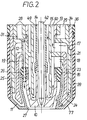
- annular channel 75 is formed, which runs over most of its length parallel to the main axis of the burner and has a conical shape 76 in the area in front of the end face of the nozzle end piece 11 .
- the conical course 76 of the ring channel 75 in the mouth area is formed by the outer surface of the nozzle end piece 11 and a conical inner surface of the nozzle jacket 68. Both conical surfaces have a coating 77 or 78 made of ceramic.
- the inside diameter of the nozzle jacket 68 on its end face is smaller than the outside diameter of the nozzle end piece 11, so that the end face of the cooled nozzle jacket 68 for the ceramic tube 39 provides heat protection against the hot atmosphere surrounding the plasma torch or the burner arc.
- spacer or support bodies 80 are attached to the insulation tube 36 comprising the electrode lance and extend as far as the inner tube 72 of the torch jacket.
- displacement body 81 (FIG. 3) can also be attached to the insulation tube 36.
Landscapes
- Physics & Mathematics (AREA)
- Engineering & Computer Science (AREA)
- Plasma & Fusion (AREA)
- Spectroscopy & Molecular Physics (AREA)
- Plasma Technology (AREA)
- Arc Welding In General (AREA)
- Pressure-Spray And Ultrasonic-Wave- Spray Burners (AREA)
- Manufacture And Refinement Of Metals (AREA)
- Discharge Heating (AREA)
- Manufacture, Treatment Of Glass Fibers (AREA)
- Macromolecular Compounds Obtained By Forming Nitrogen-Containing Linkages In General (AREA)
- Developing Agents For Electrophotography (AREA)
Applications Claiming Priority (2)
| Application Number | Priority Date | Filing Date | Title |
|---|---|---|---|
| DE4022111 | 1990-07-11 | ||
| DE4022111A DE4022111A1 (de) | 1990-07-11 | 1990-07-11 | Plasmabrenner fuer uebertragenen lichtbogen |
Publications (3)
| Publication Number | Publication Date |
|---|---|
| EP0465941A2 true EP0465941A2 (fr) | 1992-01-15 |
| EP0465941A3 EP0465941A3 (en) | 1992-07-01 |
| EP0465941B1 EP0465941B1 (fr) | 1997-04-23 |
Family
ID=6410097
Family Applications (1)
| Application Number | Title | Priority Date | Filing Date |
|---|---|---|---|
| EP91110640A Expired - Lifetime EP0465941B1 (fr) | 1990-07-11 | 1991-06-27 | Torche à plasma à arc transféré |
Country Status (11)
| Country | Link |
|---|---|
| US (1) | US5206481A (fr) |
| EP (1) | EP0465941B1 (fr) |
| JP (1) | JPH04229995A (fr) |
| KR (1) | KR100203089B1 (fr) |
| AT (1) | ATE152314T1 (fr) |
| CA (1) | CA2045844A1 (fr) |
| DE (2) | DE4022111A1 (fr) |
| ES (1) | ES2100184T3 (fr) |
| FI (1) | FI103250B (fr) |
| NO (1) | NO912474L (fr) |
| ZA (1) | ZA915358B (fr) |
Cited By (3)
| Publication number | Priority date | Publication date | Assignee | Title |
|---|---|---|---|---|
| EP0510816A3 (en) * | 1991-04-25 | 1993-01-07 | Tetronics Research & Development Company Limited | Process and apparatus for the production of fused silica |
| DE4440323A1 (de) * | 1994-11-11 | 1996-05-15 | Sulzer Metco Ag | Düse für einen Brennerkopf eines Plasmaspritzgeräts |
| EP0748149A1 (fr) * | 1995-06-05 | 1996-12-11 | The Esab Group, Inc. | Torche à plasma d'arc comportant un arrangement de buse avec injection d'eau |
Families Citing this family (24)
| Publication number | Priority date | Publication date | Assignee | Title |
|---|---|---|---|---|
| DE4034731A1 (de) * | 1990-10-30 | 1992-05-07 | Mannesmann Ag | Plasmabrenner zum schmelzen und warmhalten von in gefaessen zu behandelnden materialien |
| US5455401A (en) * | 1994-10-12 | 1995-10-03 | Aerojet General Corporation | Plasma torch electrode |
| FR2735939B1 (fr) * | 1995-06-20 | 1997-09-26 | Aerospatiale | Dispositif de refroidissement externe d'une torche a plasma |
| US6998566B2 (en) * | 2002-04-19 | 2006-02-14 | Thermal Dynamics Corporation | Plasma arc torch electrode |
| JP2005118816A (ja) * | 2003-10-16 | 2005-05-12 | Koike Sanso Kogyo Co Ltd | プラズマトーチ用のノズル |
| KR100886872B1 (ko) | 2007-06-22 | 2009-03-06 | 홍용철 | 플라즈마 버너 |
| US8257455B2 (en) * | 2007-07-30 | 2012-09-04 | Korea Institute Of Machinery & Materials | Plasma burner and diesel particulate filter trap |
| TWI352368B (en) * | 2007-09-21 | 2011-11-11 | Ind Tech Res Inst | Plasma head and plasma-discharging device using th |
| IT1392379B1 (it) * | 2008-12-24 | 2012-03-02 | Cebora Spa | Torcia al plasma ad elevate prestazioni. |
| DE102009009451A1 (de) * | 2009-02-13 | 2010-08-19 | Siemens Aktiengesellschaft | Schaltgeräteanordnung mit einer Schaltstrecke |
| DE102009031857C5 (de) * | 2009-07-03 | 2017-05-11 | Kjellberg Finsterwalde Plasma Und Maschinen Gmbh | Düse für einen flüssigkeitsgekühlten Plasmabrenner sowie Plasmabrennerkopf mit derselben |
| CA2765449C (fr) | 2009-07-03 | 2014-10-21 | Kjellberg Finsterwalde Plasma Und Maschinen Gmbh | Tuyere pour une torche a plasma refroidie par liquide ainsi que tete de torche a plasma munie de celle-ci |
| ITBO20120375A1 (it) * | 2012-07-11 | 2014-01-12 | Tec Mo S R L | Dispositivo a torcia al plasma raffreddato |
| DE102012213453A1 (de) * | 2012-07-31 | 2014-02-06 | Siemens Aktiengesellschaft | Brenner für das Wolfram-Inertgas-Schweißen |
| DE102013103508A1 (de) * | 2013-04-09 | 2014-10-09 | PLASMEQ GmbH | Plasmabrenner |
| US9144148B2 (en) | 2013-07-25 | 2015-09-22 | Hypertherm, Inc. | Devices for gas cooling plasma arc torches and related systems and methods |
| CA2956968A1 (fr) * | 2014-08-11 | 2016-02-18 | Best Theratronics Ltd. | Systeme et procede pour la separation d'isotope metallique par un processus de distillation thermique-sous vide combine |
| DE102014219275A1 (de) * | 2014-09-24 | 2016-03-24 | Siemens Aktiengesellschaft | Zündung von Flammen eines elektropositiven Metalls durch Plasmatisierung des Reaktionsgases |
| WO2017180551A1 (fr) * | 2016-04-11 | 2017-10-19 | Hypertherm, Inc. | Système de coupe à arc à plasma comprenant des anneaux de tourbillonnement, et autres consommables, et procédés de fonctionnement associés |
| GB2568106B (en) * | 2017-11-07 | 2022-09-21 | Tetronics Tech Limited | Plasma Torch Assembly |
| CN110056893A (zh) * | 2019-05-21 | 2019-07-26 | 成都高鑫焊割科技有限公司 | 一种有害气体焚烧裂解处理器 |
| US12484138B2 (en) | 2019-10-04 | 2025-11-25 | Kennametal Inc. | Coated nozzles for arc torches |
| JP7474676B2 (ja) * | 2020-10-19 | 2024-04-25 | コマツ産機株式会社 | プラズマトーチ及びプラズマトーチ用センタパイプ |
| CZ309391B6 (cs) * | 2021-09-24 | 2022-11-09 | Thermacut, K.S. | Směrovací dílec pro plazmový hořák, sestava a plazmový hořák |
Family Cites Families (16)
| Publication number | Priority date | Publication date | Assignee | Title |
|---|---|---|---|---|
| US3147329A (en) * | 1955-07-26 | 1964-09-01 | Union Carbide Corp | Method and apparatus for heating metal melting furnaces |
| DE1256816B (de) * | 1965-04-09 | 1967-12-21 | Inst Badan Jadrowych | Bogenplasmabrenner |
| US4082914A (en) * | 1973-05-14 | 1978-04-04 | Nikolai Iosifovich Bortnichuk | Method of stabilizing arc voltage in plasma arc furnace and apparatus for effecting same |
| CH593754A5 (fr) * | 1976-01-15 | 1977-12-15 | Castolin Sa | |
| DE2900330A1 (de) * | 1978-01-09 | 1979-07-12 | Inst Elektroswarki Patona | Verfahren zur plasmaerzeugung in einem plasma-lichtbogen-generator und vorrichtung zur durchfuehrung des verfahrens |
| SU766088A1 (ru) * | 1978-07-14 | 1982-06-23 | Всесоюзный Научно-Исследовательский Институт По Монтажным И Специальным Строительным Работам | Горелка дл дуговой обработки |
| CA1173784A (fr) * | 1981-07-30 | 1984-09-04 | William H. Gauvin | Reacteur a transport d'arc au plasma pour la chimie et la metallurgie |
| DE3328777A1 (de) * | 1983-08-10 | 1985-02-28 | Fried. Krupp Gmbh, 4300 Essen | Plasmabrenner und verfahren zu dessen betreiben |
| DE3426410A1 (de) * | 1984-07-18 | 1986-01-23 | Süddeutsche Kühlerfabrik Julius Fr. Behr GmbH & Co KG, 7000 Stuttgart | Schweissbrenner zum plasma-mig-schweissen |
| US4628177A (en) * | 1984-08-10 | 1986-12-09 | B & B Precision Machines, Inc. | Arc welding torch |
| DE3435680A1 (de) * | 1984-09-28 | 1986-04-03 | Fried. Krupp Gmbh, 4300 Essen | Plasmabrenner |
| JPH0658840B2 (ja) * | 1988-04-26 | 1994-08-03 | 新日本製鐵株式会社 | 移行形プラズマトーチ |
| US5132512A (en) * | 1988-06-07 | 1992-07-21 | Hypertherm, Inc. | Arc torch nozzle shield for plasma |
| JPH0220667A (ja) * | 1988-07-06 | 1990-01-24 | Origin Electric Co Ltd | プラズマトーチ |
| JPH082500B2 (ja) * | 1988-07-27 | 1996-01-17 | 松下電器産業株式会社 | プラズマ切断トーチ |
| US5124525A (en) * | 1991-08-27 | 1992-06-23 | Esab Welding Products, Inc. | Plasma arc torch having improved nozzle assembly |
-
1990
- 1990-07-11 DE DE4022111A patent/DE4022111A1/de not_active Withdrawn
-
1991
- 1991-06-20 FI FI913024A patent/FI103250B/fi active
- 1991-06-25 NO NO91912474A patent/NO912474L/no unknown
- 1991-06-27 EP EP91110640A patent/EP0465941B1/fr not_active Expired - Lifetime
- 1991-06-27 AT AT91110640T patent/ATE152314T1/de not_active IP Right Cessation
- 1991-06-27 DE DE59108674T patent/DE59108674D1/de not_active Expired - Fee Related
- 1991-06-27 CA CA002045844A patent/CA2045844A1/fr not_active Abandoned
- 1991-06-27 ES ES91110640T patent/ES2100184T3/es not_active Expired - Lifetime
- 1991-07-02 US US07/725,628 patent/US5206481A/en not_active Expired - Fee Related
- 1991-07-09 JP JP3168416A patent/JPH04229995A/ja active Pending
- 1991-07-10 ZA ZA915358A patent/ZA915358B/xx unknown
- 1991-07-11 KR KR1019910011761A patent/KR100203089B1/ko not_active Expired - Fee Related
Cited By (4)
| Publication number | Priority date | Publication date | Assignee | Title |
|---|---|---|---|---|
| EP0510816A3 (en) * | 1991-04-25 | 1993-01-07 | Tetronics Research & Development Company Limited | Process and apparatus for the production of fused silica |
| DE4440323A1 (de) * | 1994-11-11 | 1996-05-15 | Sulzer Metco Ag | Düse für einen Brennerkopf eines Plasmaspritzgeräts |
| EP0748149A1 (fr) * | 1995-06-05 | 1996-12-11 | The Esab Group, Inc. | Torche à plasma d'arc comportant un arrangement de buse avec injection d'eau |
| US5660743A (en) * | 1995-06-05 | 1997-08-26 | The Esab Group, Inc. | Plasma arc torch having water injection nozzle assembly |
Also Published As
| Publication number | Publication date |
|---|---|
| FI913024A0 (fi) | 1991-06-20 |
| EP0465941A3 (en) | 1992-07-01 |
| FI103250B1 (fi) | 1999-05-14 |
| FI913024A7 (fi) | 1992-01-12 |
| ZA915358B (en) | 1992-04-29 |
| ATE152314T1 (de) | 1997-05-15 |
| FI103250B (fi) | 1999-05-14 |
| DE4022111A1 (de) | 1992-01-23 |
| NO912474L (no) | 1992-01-13 |
| CA2045844A1 (fr) | 1992-01-12 |
| EP0465941B1 (fr) | 1997-04-23 |
| JPH04229995A (ja) | 1992-08-19 |
| ES2100184T3 (es) | 1997-06-16 |
| US5206481A (en) | 1993-04-27 |
| KR920003820A (ko) | 1992-02-29 |
| DE59108674D1 (de) | 1997-05-28 |
| NO912474D0 (no) | 1991-06-25 |
| KR100203089B1 (ko) | 1999-06-15 |
Similar Documents
| Publication | Publication Date | Title |
|---|---|---|
| EP0465941B1 (fr) | Torche à plasma à arc transféré | |
| DE4132850C2 (de) | Brenner für die Verbrennung von feinkörnigen bis staubförmigen festen Brennstoffen | |
| EP0538293B1 (fr) | Chalumeau a plasma a arc electrique transmis | |
| DD151401A1 (de) | Mittels gasgemischen betriebener plasmabrenner | |
| DE2912843A1 (de) | Plasmabrenner, plasmabrenneranordnung und verfahren zur plasmaerzeugung | |
| WO1985000991A1 (fr) | Installation de pulverisation thermique de materiaux de soudage d'apport | |
| DE2818304A1 (de) | Verfahren und vorrichtung zum plasmaspritzen eines ueberzugmaterials auf eine unterlage | |
| DE4030541C2 (de) | Brenner zur Beschichtung von Grundwerkstoffen mit pulverförmigen Zusatzwerkstoffen | |
| DE2839485A1 (de) | Brenner zum mikroplasmaschweissen | |
| DE2416422A1 (de) | Verfahren und vorrichtung zum lichtbogenschweissen | |
| DE3435680A1 (de) | Plasmabrenner | |
| DE2818303A1 (de) | Verfahren und vorrichtung zum plasmaspritzen eines ueberzugmaterials auf eine unterlage | |
| DE2633510B2 (de) | Plasmatron | |
| DE3426410A1 (de) | Schweissbrenner zum plasma-mig-schweissen | |
| DE3328777A1 (de) | Plasmabrenner und verfahren zu dessen betreiben | |
| DD292806A5 (de) | Fluessigkeitsgekuehlter plasmabrenner mit uebertragenem lichtbogen | |
| DE1764116B1 (de) | Lichtbogen plasmastrahlgenerator | |
| DE1546810A1 (de) | Vorrichtung zum Ausstoss von pulverfoermigem Material mittels eines ionisierten Gasstrahles | |
| DE102007041329B4 (de) | Plasmabrenner mit axialer Pulvereindüsung | |
| EP0115247B1 (fr) | Installation de brûleur pour fours de verrerie | |
| EP0094984A1 (fr) | Chalumeau soudeur ou coupeur à l'arc | |
| DE1075765B (de) | Lichtbogenbrenner mit nicht abschmelzender Elektrode und gasumhülltem, eingeschnürtem Lichtbogen | |
| WO2008000586A1 (fr) | Procédé et dispositif pour introduire des poussières dans un bain de fusion d'installation pyrométallurgique | |
| EP0183978A2 (fr) | Brûleur | |
| EP0411272A1 (fr) | Chalumeau soudeur en atmosphère gazeuse |
Legal Events
| Date | Code | Title | Description |
|---|---|---|---|
| PUAI | Public reference made under article 153(3) epc to a published international application that has entered the european phase |
Free format text: ORIGINAL CODE: 0009012 |
|
| AK | Designated contracting states |
Kind code of ref document: A2 Designated state(s): AT BE DE ES FR GB IT LU NL SE |
|
| PUAL | Search report despatched |
Free format text: ORIGINAL CODE: 0009013 |
|
| AK | Designated contracting states |
Kind code of ref document: A3 Designated state(s): AT BE DE ES FR GB IT LU NL SE |
|
| 17P | Request for examination filed |
Effective date: 19921208 |
|
| 17Q | First examination report despatched |
Effective date: 19950210 |
|
| RAP1 | Party data changed (applicant data changed or rights of an application transferred) |
Owner name: FRIED. KRUPP AG HOESCH-KRUPP |
|
| GRAG | Despatch of communication of intention to grant |
Free format text: ORIGINAL CODE: EPIDOS AGRA |
|
| GRAH | Despatch of communication of intention to grant a patent |
Free format text: ORIGINAL CODE: EPIDOS IGRA |
|
| GRAH | Despatch of communication of intention to grant a patent |
Free format text: ORIGINAL CODE: EPIDOS IGRA |
|
| GRAA | (expected) grant |
Free format text: ORIGINAL CODE: 0009210 |
|
| AK | Designated contracting states |
Kind code of ref document: B1 Designated state(s): AT BE DE ES FR GB IT LU NL SE |
|
| REF | Corresponds to: |
Ref document number: 152314 Country of ref document: AT Date of ref document: 19970515 Kind code of ref document: T |
|
| GBT | Gb: translation of ep patent filed (gb section 77(6)(a)/1977) |
Effective date: 19970424 |
|
| REF | Corresponds to: |
Ref document number: 59108674 Country of ref document: DE Date of ref document: 19970528 |
|
| REG | Reference to a national code |
Ref country code: ES Ref legal event code: FG2A Ref document number: 2100184 Country of ref document: ES Kind code of ref document: T3 |
|
| ET | Fr: translation filed | ||
| PLBE | No opposition filed within time limit |
Free format text: ORIGINAL CODE: 0009261 |
|
| STAA | Information on the status of an ep patent application or granted ep patent |
Free format text: STATUS: NO OPPOSITION FILED WITHIN TIME LIMIT |
|
| 26N | No opposition filed | ||
| PGFP | Annual fee paid to national office [announced via postgrant information from national office to epo] |
Ref country code: GB Payment date: 19980514 Year of fee payment: 8 |
|
| PGFP | Annual fee paid to national office [announced via postgrant information from national office to epo] |
Ref country code: NL Payment date: 19980518 Year of fee payment: 8 Ref country code: FR Payment date: 19980518 Year of fee payment: 8 |
|
| PGFP | Annual fee paid to national office [announced via postgrant information from national office to epo] |
Ref country code: SE Payment date: 19980525 Year of fee payment: 8 |
|
| PGFP | Annual fee paid to national office [announced via postgrant information from national office to epo] |
Ref country code: AT Payment date: 19980527 Year of fee payment: 8 |
|
| PGFP | Annual fee paid to national office [announced via postgrant information from national office to epo] |
Ref country code: BE Payment date: 19980615 Year of fee payment: 8 |
|
| PGFP | Annual fee paid to national office [announced via postgrant information from national office to epo] |
Ref country code: ES Payment date: 19980616 Year of fee payment: 8 |
|
| PGFP | Annual fee paid to national office [announced via postgrant information from national office to epo] |
Ref country code: LU Payment date: 19980922 Year of fee payment: 8 |
|
| PG25 | Lapsed in a contracting state [announced via postgrant information from national office to epo] |
Ref country code: LU Free format text: LAPSE BECAUSE OF NON-PAYMENT OF DUE FEES Effective date: 19990627 Ref country code: GB Free format text: LAPSE BECAUSE OF NON-PAYMENT OF DUE FEES Effective date: 19990627 Ref country code: AT Free format text: LAPSE BECAUSE OF NON-PAYMENT OF DUE FEES Effective date: 19990627 |
|
| PG25 | Lapsed in a contracting state [announced via postgrant information from national office to epo] |
Ref country code: ES Free format text: LAPSE BECAUSE OF EXPIRATION OF PROTECTION Effective date: 19990628 |
|
| PG25 | Lapsed in a contracting state [announced via postgrant information from national office to epo] |
Ref country code: SE Free format text: THE PATENT HAS BEEN ANNULLED BY A DECISION OF A NATIONAL AUTHORITY Effective date: 19990629 |
|
| PG25 | Lapsed in a contracting state [announced via postgrant information from national office to epo] |
Ref country code: FR Free format text: THE PATENT HAS BEEN ANNULLED BY A DECISION OF A NATIONAL AUTHORITY Effective date: 19990630 Ref country code: BE Free format text: LAPSE BECAUSE OF NON-PAYMENT OF DUE FEES Effective date: 19990630 |
|
| PGFP | Annual fee paid to national office [announced via postgrant information from national office to epo] |
Ref country code: DE Payment date: 19990804 Year of fee payment: 9 |
|
| BERE | Be: lapsed |
Owner name: FRIED. KRUPP A.G. HOESCH-KRUPP Effective date: 19990630 |
|
| PG25 | Lapsed in a contracting state [announced via postgrant information from national office to epo] |
Ref country code: NL Free format text: LAPSE BECAUSE OF NON-PAYMENT OF DUE FEES Effective date: 20000101 |
|
| GBPC | Gb: european patent ceased through non-payment of renewal fee |
Effective date: 19990627 |
|
| EUG | Se: european patent has lapsed |
Ref document number: 91110640.9 |
|
| NLV4 | Nl: lapsed or anulled due to non-payment of the annual fee |
Effective date: 20000101 |
|
| REG | Reference to a national code |
Ref country code: FR Ref legal event code: ST |
|
| PG25 | Lapsed in a contracting state [announced via postgrant information from national office to epo] |
Ref country code: DE Free format text: LAPSE BECAUSE OF NON-PAYMENT OF DUE FEES Effective date: 20010403 |
|
| REG | Reference to a national code |
Ref country code: ES Ref legal event code: FD2A Effective date: 20010601 |
|
| PG25 | Lapsed in a contracting state [announced via postgrant information from national office to epo] |
Ref country code: IT Free format text: LAPSE BECAUSE OF NON-PAYMENT OF DUE FEES;WARNING: LAPSES OF ITALIAN PATENTS WITH EFFECTIVE DATE BEFORE 2007 MAY HAVE OCCURRED AT ANY TIME BEFORE 2007. THE CORRECT EFFECTIVE DATE MAY BE DIFFERENT FROM THE ONE RECORDED. Effective date: 20050627 |