EP0465966B1 - Echelle de mesure - Google Patents
Echelle de mesure Download PDFInfo
- Publication number
- EP0465966B1 EP0465966B1 EP91110826A EP91110826A EP0465966B1 EP 0465966 B1 EP0465966 B1 EP 0465966B1 EP 91110826 A EP91110826 A EP 91110826A EP 91110826 A EP91110826 A EP 91110826A EP 0465966 B1 EP0465966 B1 EP 0465966B1
- Authority
- EP
- European Patent Office
- Prior art keywords
- adhesive layer
- base body
- graduation
- adhesive
- graduation carrier
- Prior art date
- Legal status (The legal status is an assumption and is not a legal conclusion. Google has not performed a legal analysis and makes no representation as to the accuracy of the status listed.)
- Expired - Lifetime
Links
Images
Classifications
-
- G—PHYSICS
- G01—MEASURING; TESTING
- G01D—MEASURING NOT SPECIALLY ADAPTED FOR A SPECIFIC VARIABLE; ARRANGEMENTS FOR MEASURING TWO OR MORE VARIABLES NOT COVERED IN A SINGLE OTHER SUBCLASS; TARIFF METERING APPARATUS; MEASURING OR TESTING NOT OTHERWISE PROVIDED FOR
- G01D5/00—Mechanical means for transferring the output of a sensing member; Means for converting the output of a sensing member to another variable where the form or nature of the sensing member does not constrain the means for converting; Transducers not specially adapted for a specific variable
- G01D5/26—Mechanical means for transferring the output of a sensing member; Means for converting the output of a sensing member to another variable where the form or nature of the sensing member does not constrain the means for converting; Transducers not specially adapted for a specific variable characterised by optical transfer means, i.e. using infrared, visible, or ultraviolet light
- G01D5/32—Mechanical means for transferring the output of a sensing member; Means for converting the output of a sensing member to another variable where the form or nature of the sensing member does not constrain the means for converting; Transducers not specially adapted for a specific variable characterised by optical transfer means, i.e. using infrared, visible, or ultraviolet light with attenuation or whole or partial obturation of beams of light
- G01D5/34—Mechanical means for transferring the output of a sensing member; Means for converting the output of a sensing member to another variable where the form or nature of the sensing member does not constrain the means for converting; Transducers not specially adapted for a specific variable characterised by optical transfer means, i.e. using infrared, visible, or ultraviolet light with attenuation or whole or partial obturation of beams of light the beams of light being detected by photocells
- G01D5/347—Mechanical means for transferring the output of a sensing member; Means for converting the output of a sensing member to another variable where the form or nature of the sensing member does not constrain the means for converting; Transducers not specially adapted for a specific variable characterised by optical transfer means, i.e. using infrared, visible, or ultraviolet light with attenuation or whole or partial obturation of beams of light the beams of light being detected by photocells using displacement encoding scales
- G01D5/34707—Scales; Discs, e.g. fixation, fabrication, compensation
Definitions
- the invention relates to a material measure according to the preamble of claim 1.
- Such a material measure is used in particular in a position measuring device for measuring the relative position of two objects, for example two machine parts of a processing machine.
- a length measuring device in which a graduation carrier is fastened to a housing as a base body without direct contact by means of an elastic adhesive layer in order to avoid measurement inaccuracies in the case of different coefficients of thermal expansion of the base body and the graduation carrier.
- DE-GM 89 11 313 shows a material measure in which a graduation carrier made of glass on a base made of steel by means of a thin inelastic Adhesive layer is attached from a hard adhesive in order to force the temperature behavior of the base body made of steel over the thin hard adhesive layer on the graduation carrier made of glass so that the material measure approximately corresponds to the temperature behavior of the machine part made of steel to which it is attached.
- depressions are provided in the adhesive surface of the base body and / or in the adhesive surface of the graduation carrier for receiving the excess hard adhesive during the gluing process.
- DE-AS 26 43 304 describes a length measuring device in which a graduation carrier rests as a base body on the edges of a rectangular groove of a housing running in the measuring direction.
- the graduation carrier is connected in the middle by means of an inelastic adhesive in the groove and on both sides by means of a highly elastic adhesive in the groove to the base body in order to achieve a thermal expansion which is independent of the base body and uniformly from its center, so that the center of the graduation carrier maintains its position with respect to the base body unchanged.
- the adhesion of the adhesive layer to the adhesive surfaces of the base body and / or the division carrier is more or less good, depending on their surface properties, depending on the cleaning, so that at least partial detachment of the adhesive layer from the adhesive surfaces of the base body and / or the division carrier can occur , whereby the flatness of the graduation area of the graduation carrier is impaired and the scanning distance between this graduation area and the scanning graduation area of the Scanning unit are changed, which can lead to measurement inaccuracies as well as malfunctions.
- the invention has for its object to ensure reliable adhesion of the adhesive layer to the adhesive surfaces of the base body and / or the graduation carrier in a material measure of the type mentioned.
- the advantages achieved by the invention are, in particular, that their detachment is reliably avoided by the proposed form-fitting attachment of the adhesive layer to the adhesive surfaces of the base body and / or the division carrier, so that no measurement inaccuracies resulting therefrom can occur.
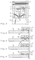
- FIG. 1 shows a cross section of an encapsulated length measuring device for measuring the relative position of two objects, the housing 1 of which is connected as a base body to the one object 2 by means of screws 3.
- a division carrier 5 is fastened to a contact surface 4 by means of an adhesive layer 6 in a known manner.
- a scanning unit 7 for scanning the division of the graduation carrier 5 is guided on its division level by means of rollers 8 and connected via a coupling (not shown) to a driver 9 which is fastened to the second object 11 via a mounting element 10.
- the housing 1 has a longitudinal slot 12 in the measuring direction, which is closed by two roof-shaped inclined sealing lips 13, through which the driver 9 engages with its double-sword-shaped part 9a.
- the two objects 2, 11 can be formed by two machine parts of a processing machine, not shown.
- the adhesive layer 6 is positively attached to the base body 1 and / or to the graduation carrier 5.
- Figure 2 shows a first enlarged scale of the length measuring device according to Figure 1 in cross section.
- the division carrier 5a with the division is attached to the contact surface 4a of the base body 1a in the form of the housing by means of the adhesive layer 6a.
- the base body 1a is made of aluminum and the graduation carrier 5a is made of glass. While the adhesion of the adhesive layer 6a to the adhesive surface 14a of the dividing support 5a made of glass is sufficient for a secure attachment, the base body 1a made of aluminum can at least partially detach the adhesive layer 6a from the adhesive surface 15a of the base body 1a.
- the adhesive layer 6a engages in a recess Na in the form of a dovetail-shaped groove in the adhesive surface 15a of the base body 1a by means of a projection Va; this projection Va fills the entire groove Na, so that a secure adhesion of the adhesive layer 6a to the adhesive surface 15a of the base body 1a is ensured.
- FIG. 3 shows a second measuring standard in cross section, in which the graduation carrier 5b is fastened with the graduation on the contact surface 4b of the base body 1b in the form of the housing by means of the adhesive layer 6b.
- the adhesive layer 6b engages by means of two projections Vb in two recesses Nb in the form of dovetail-shaped grooves in the adhesive surface 15b of the base body 1b and by means of a projection Vb in a recess Nb in the form of a dovetail-shaped groove in the adhesive surface 14b of the graduation carrier 5b; these projections Vb fill the entire grooves, so that a secure adhesion of the adhesive layer 6b to the adhesive surface 15b of the base body 1b and to the adhesive surface 14b of the graduation carrier 5b is ensured.
- Figure 4 shows a third measuring standard in cross section, in which the graduation carrier 5c with the graduation is attached to the contact surface 4c of the base body 1c in the form of the housing by means of the adhesive layer 6c.
- the adhesive layer 6c engages by means of a projection Vc in a recess Nc in the form of a T-shaped groove in the adhesive surface 15c of the base body 1c; this projection Vc fills the entire groove Nc, so that a secure adhesion of the adhesive layer 6c to the adhesive surface 15c of the base body 1c is ensured.
- FIG. 5 shows a fourth measuring standard in cross section, in which the division carrier 5d is fastened with the division on the contact surface 4d of the base body 1d in the form of the housing by means of the adhesive layer 6d.
- the adhesive layer 6d encompasses a dovetail-shaped projection P on the adhesive surface 15d of the base body 1d, so that secure adhesion of the adhesive layer 6d to the adhesive surface 15d of the base body 1d is ensured.
- the adhesive layer 6 preferably consists of an elastic adhesive, for example of silicone rubber.
- the at least one groove N can run continuously or partially in the area of the adhesive surface 14, 15 and extend in the measuring direction and / or transverse to the measuring direction.
- the cross sections of the depressions N or the projections P of the base body 1 and / or the graduation carrier 5 can of course be of any type; It is essential that an undercut results in a form-fitting attachment of the adhesive layer 6 on the adhesive surfaces 15, 14 of the base body 1 and / or of the division carrier 5.
- the invention can also be used with an angle measuring device, as described for example in DE-AS 28 41 501.
- the invention can also be used with an open, that is to say unencapsulated, measuring device.
- any combination of depressions and projections can also be provided in the adhesive surfaces of the base body and / or of the division carrier.
Landscapes
- Physics & Mathematics (AREA)
- General Physics & Mathematics (AREA)
- Transmission And Conversion Of Sensor Element Output (AREA)
- Length-Measuring Instruments Using Mechanical Means (AREA)
- Length Measuring Devices With Unspecified Measuring Means (AREA)
- Glass Compositions (AREA)
- Analysing Materials By The Use Of Radiation (AREA)
- Crystals, And After-Treatments Of Crystals (AREA)
- Semiconductor Lasers (AREA)
Claims (8)
- Mesure matérialisée, en particulier pour un dispositif de mesure de position, dans laquelle un support de graduation portant une graduation est fixé au moyen d'une couche d'adhésif sur un corps de base, caractérisée par le fait que le corps de base (1) et/ou le support de graduation (5) présente au moins une rainure (N) et/ou une saillie (P) continue ou partielle de type contre-dépouille et par le fait que la couche d'adhésif (6) disposée entre le corps de base (1) et le support de graduation (5), aux fins d'éviter un décollement de ceux-ci, remplit la rainure (N) ou entoure la saillie (P) en réalisant une liaison par obstacle.
- Mesure matérialisée selon la revendication 1, caractérisée par le fait que la rainure (Na) présente une section transversale en queue d'aronde.
- Mesure matérialisée selon la revendication 1, caractérisée par le fait que la rainure (Nc) présente une section transversale en T.
- Mesure matérialisée selon la revendication 1, caractérisée par le fait que la saillie (P) présente une section transversale en queue d'aronde.
- Mesure matérialisée selon la revendication 1, caractérisée par le fait que la couche d'adhésif (6) se compose d'une colle élastique.
- Mesure matérialisée selon les revendications 1 à 4, caractérisée par le fait que la rainure (N) et/ou la saillie (P) s'étendent dans la direction de mesure et/ou transversalement à celle-ci.
- Mesure matérialisée selon la revendication 1 en tant que partie d'un dispositif de mesure de longueur étanche, caractérisée par le fait que le corps de base (1) constitue simultanément le boîtier pour le support de graduation (5) et pour une unité de lecture (7) qui lit la graduation du support de graduation (5), par le fait que le support de graduation (5) est fixé sur une surface (4) du corps de base (1) au moyen de la couche (6) élastique d'adhésif et par le fait que la couche d'adhésif (6) pénètre en réalisant une liaison par obstacle par au moins une saillie (V) dans au moins une dépression (N) dans la surface (15) de collage du boîtier (1).
- Mesure matérialisée selon la revendication 7, caractérisée par le fait que le boîtier (1) est en aluminium et que le support de graduation (5) est en verre.
Applications Claiming Priority (2)
| Application Number | Priority Date | Filing Date | Title |
|---|---|---|---|
| DE4021919 | 1990-07-10 | ||
| DE4021919A DE4021919C2 (de) | 1990-07-10 | 1990-07-10 | Maßverkörperung |
Publications (3)
| Publication Number | Publication Date |
|---|---|
| EP0465966A2 EP0465966A2 (fr) | 1992-01-15 |
| EP0465966A3 EP0465966A3 (en) | 1992-08-05 |
| EP0465966B1 true EP0465966B1 (fr) | 1995-05-31 |
Family
ID=6410005
Family Applications (1)
| Application Number | Title | Priority Date | Filing Date |
|---|---|---|---|
| EP91110826A Expired - Lifetime EP0465966B1 (fr) | 1990-07-10 | 1991-06-29 | Echelle de mesure |
Country Status (5)
| Country | Link |
|---|---|
| US (1) | US5157846A (fr) |
| EP (1) | EP0465966B1 (fr) |
| JP (1) | JPH0820244B2 (fr) |
| AT (1) | ATE123336T1 (fr) |
| DE (2) | DE4021919C2 (fr) |
Families Citing this family (12)
| Publication number | Priority date | Publication date | Assignee | Title |
|---|---|---|---|---|
| DE4320728C2 (de) * | 1993-06-23 | 2001-08-02 | Heidenhain Gmbh Dr Johannes | Lagemeßeinrichtung |
| DE4406797C2 (de) * | 1994-03-02 | 1997-11-27 | Heidenhain Gmbh Dr Johannes | Positionsmeßeinrichtung |
| DE4406799C2 (de) * | 1994-03-02 | 1997-11-06 | Heidenhain Gmbh Dr Johannes | Positionsmeßeinrichtung |
| DE4424649C2 (de) * | 1994-07-13 | 1997-11-20 | Heidenhain Gmbh Dr Johannes | Positionsmeßeinrichtung |
| DE19543647C2 (de) * | 1995-11-23 | 2000-05-04 | Heidenhain Gmbh Dr Johannes | Längenmeßeinrichtung zur Messung der Relativlage zweier Objekte |
| JPH11190601A (ja) * | 1997-12-26 | 1999-07-13 | Mitsutoyo Corp | マイクロメータ |
| DE19912310B4 (de) * | 1999-03-19 | 2007-11-29 | Dr. Johannes Heidenhain Gmbh | Positionsmeßeinrichtung |
| JP4477442B2 (ja) * | 2004-07-20 | 2010-06-09 | 株式会社ミツトヨ | リニアスケール固定装置及び固定方法 |
| DE102009001212A1 (de) * | 2009-02-27 | 2010-09-02 | Dr. Johannes Heidenhain Gmbh | Baueinheit für eine Winkelmesseinrichtung und entsprechende Winkelmesseinrichtung |
| JP2012147203A (ja) * | 2011-01-11 | 2012-08-02 | Smk Corp | センサモジュール |
| JP6482394B2 (ja) * | 2015-06-15 | 2019-03-13 | 三菱電機株式会社 | 光学式エンコーダ |
| WO2017154938A1 (fr) | 2016-03-09 | 2017-09-14 | 株式会社糖鎖工学研究所 | Procédé de production de sucre contenant un groupe sulfate et/ou un groupe phosphate |
Family Cites Families (18)
| Publication number | Priority date | Publication date | Assignee | Title |
|---|---|---|---|---|
| US1148584A (en) * | 1914-04-06 | 1915-08-03 | Edward W Gerrish | Method of utilizing scrap pieces of material. |
| JPS519772Y2 (fr) * | 1971-03-05 | 1976-03-16 | ||
| DE2505587C3 (de) * | 1975-02-11 | 1980-10-09 | Dr. Johannes Heidenhain Gmbh, 8225 Traunreut | Längenmeßeinrichtung |
| CH594875A5 (fr) * | 1975-02-11 | 1978-01-31 | Heidenhain Gmbh Dr Johannes | |
| DE2643304B2 (de) * | 1976-09-25 | 1980-01-31 | Fagor Electrotecnica, Sdad.Coop., Mondragon, Guipuzcoa (Spanien) | Photoelektrische Einrichtung zum Messen der relativen Lage von Gegenständen |
| US4086382A (en) * | 1977-01-05 | 1978-04-25 | American Door Company Of Michigan, Inc. | Method of producing fire resistant wood products and product thereof |
| DE2841501B2 (de) * | 1978-09-23 | 1980-12-18 | Dr. Johannes Heidenhain Gmbh, 8225 Traunreut | Gekapselte Winkelmefieinrichtung |
| DE3016908C2 (de) * | 1980-05-02 | 1982-04-15 | Dr. Johannes Heidenhain Gmbh, 8225 Traunreut | Präzisionslängenmeßeinrichtung |
| JPS5866001A (ja) * | 1981-10-15 | 1983-04-20 | Sony Magnescale Inc | 磁気スケ−ル装置 |
| DE3335784A1 (de) * | 1983-10-01 | 1985-04-11 | Schott Glaswerke, 6500 Mainz | Verfahren zur herstellung einer klebverbindung mit mechanisch wirkender hinterfangung |
| DE3410944C1 (de) * | 1984-03-24 | 1985-05-09 | Dr. Johannes Heidenhain Gmbh, 8225 Traunreut | Gekapselte Meßeinrichtung |
| US4586760A (en) * | 1984-06-01 | 1986-05-06 | Bausch & Lomb Incorporated | Measuring scale casing and mounting spar |
| JPS6135734U (ja) * | 1984-08-02 | 1986-03-05 | 株式会社 測機舎 | 磁気スケール装置の取付け機構 |
| DE3519679A1 (de) * | 1985-06-01 | 1986-12-04 | Beitz, Wolfgang, Prof.Dr.-Ing. | Verfahren zur herstellung loesbarer verbindungen (schrauben-, formschluessige welle-nabe- und linienhafte formschlussverbindungen) durch formelemente aus klebstoff |
| DE8601636U1 (de) * | 1986-01-23 | 1990-02-01 | Dr. Johannes Heidenhain Gmbh, 83301 Traunreut | Längenmeßeinrichtung |
| DE8616206U1 (de) * | 1986-06-16 | 1986-07-31 | RSF-Elektronik Gesellschaft m.b.H., Tarsdorf | Gekapselte Längenmeßeinrichtung |
| JPS63103909A (ja) * | 1986-10-20 | 1988-05-09 | Mitsutoyo Corp | 変位検出用スケ−ル |
| DE8911313U1 (de) * | 1989-09-22 | 1989-11-16 | Dr. Johannes Heidenhain Gmbh, 8225 Traunreut | Maßverkörperung |
-
1990
- 1990-07-10 DE DE4021919A patent/DE4021919C2/de not_active Expired - Fee Related
-
1991
- 1991-06-29 EP EP91110826A patent/EP0465966B1/fr not_active Expired - Lifetime
- 1991-06-29 DE DE59105612T patent/DE59105612D1/de not_active Expired - Fee Related
- 1991-06-29 AT AT91110826T patent/ATE123336T1/de not_active IP Right Cessation
- 1991-07-08 JP JP3167170A patent/JPH0820244B2/ja not_active Expired - Fee Related
- 1991-07-10 US US07/728,106 patent/US5157846A/en not_active Expired - Lifetime
Also Published As
| Publication number | Publication date |
|---|---|
| DE59105612D1 (de) | 1995-07-06 |
| EP0465966A2 (fr) | 1992-01-15 |
| EP0465966A3 (en) | 1992-08-05 |
| DE4021919C2 (de) | 1995-06-08 |
| JPH0820244B2 (ja) | 1996-03-04 |
| US5157846A (en) | 1992-10-27 |
| DE4021919A1 (de) | 1992-01-23 |
| JPH04232804A (ja) | 1992-08-21 |
| ATE123336T1 (de) | 1995-06-15 |
Similar Documents
| Publication | Publication Date | Title |
|---|---|---|
| DE3625795C2 (fr) | ||
| DE19912310B4 (de) | Positionsmeßeinrichtung | |
| EP0110059B1 (fr) | Dispositif de mesure de longueurs | |
| EP0120205B1 (fr) | Dispositif optoélectronique de mesure en capsule | |
| EP0513406B1 (fr) | Dispositif de mesure de position | |
| EP0671606B1 (fr) | Dispositif de mesure de positions | |
| EP0092651B1 (fr) | Dispositif de mesure à capot protecteur | |
| EP0465966A2 (fr) | Echelle de mesure | |
| EP0114972B1 (fr) | Dispositif pour mesurer la longueur | |
| DE69006609T2 (de) | Keramischer Deckel zum Verschliessen eines Halbleiterelements und Verfahren zum Verschliessen eines Halbleiterelements in einer keramischen Packung. | |
| DE4212970A1 (de) | Längenmeßeinrichtung | |
| EP0158050B1 (fr) | Dispositif de mesure capsulé | |
| DE19700367C2 (de) | Verfahren und Montagevorrichtung zum gerichteten Anbringen eines Maßbandes | |
| DE69106351T2 (de) | Werkzeugabnützungsdetektor. | |
| EP0681159B1 (fr) | Dispositif de mesure de position à compensation de température | |
| EP0671607B1 (fr) | Dispositif de mesure de positions | |
| EP0506649A2 (fr) | Dispositif de mesure de longueurs | |
| DE9007756U1 (de) | Maßverkörperung | |
| EP0459294A2 (fr) | Dispositif pour mesurer une position | |
| EP0163857A2 (fr) | Dispositif de mesure d'une position | |
| DE3215336C1 (de) | Gekapselte Messeinrichtung | |
| DE3431852C2 (fr) | ||
| EP0462425A1 (fr) | Dispositif de mesure blindé | |
| EP0635707B1 (fr) | Dispositif de mesure de force utilisant une résistance à couche épaisse | |
| DE8233342U1 (de) | Längenmeßeinrichtung |
Legal Events
| Date | Code | Title | Description |
|---|---|---|---|
| PUAI | Public reference made under article 153(3) epc to a published international application that has entered the european phase |
Free format text: ORIGINAL CODE: 0009012 |
|
| 17P | Request for examination filed |
Effective date: 19910713 |
|
| AK | Designated contracting states |
Kind code of ref document: A2 Designated state(s): AT CH DE ES FR GB IT LI NL SE |
|
| PUAL | Search report despatched |
Free format text: ORIGINAL CODE: 0009013 |
|
| AK | Designated contracting states |
Kind code of ref document: A3 Designated state(s): AT CH DE ES FR GB IT LI NL SE |
|
| 17Q | First examination report despatched |
Effective date: 19931129 |
|
| ITF | It: translation for a ep patent filed | ||
| GRAA | (expected) grant |
Free format text: ORIGINAL CODE: 0009210 |
|
| AK | Designated contracting states |
Kind code of ref document: B1 Designated state(s): AT CH DE ES FR GB IT LI NL SE |
|
| PG25 | Lapsed in a contracting state [announced via postgrant information from national office to epo] |
Ref country code: NL Free format text: LAPSE BECAUSE OF NON-PAYMENT OF DUE FEES Effective date: 19950531 Ref country code: ES Free format text: THE PATENT HAS BEEN ANNULLED BY A DECISION OF A NATIONAL AUTHORITY Effective date: 19950531 |
|
| REF | Corresponds to: |
Ref document number: 123336 Country of ref document: AT Date of ref document: 19950615 Kind code of ref document: T |
|
| ET | Fr: translation filed | ||
| GBT | Gb: translation of ep patent filed (gb section 77(6)(a)/1977) |
Effective date: 19950605 |
|
| REF | Corresponds to: |
Ref document number: 59105612 Country of ref document: DE Date of ref document: 19950706 |
|
| PG25 | Lapsed in a contracting state [announced via postgrant information from national office to epo] |
Ref country code: SE Effective date: 19950831 |
|
| NLV1 | Nl: lapsed or annulled due to failure to fulfill the requirements of art. 29p and 29m of the patents act | ||
| PLBE | No opposition filed within time limit |
Free format text: ORIGINAL CODE: 0009261 |
|
| STAA | Information on the status of an ep patent application or granted ep patent |
Free format text: STATUS: NO OPPOSITION FILED WITHIN TIME LIMIT |
|
| 26N | No opposition filed | ||
| REG | Reference to a national code |
Ref country code: GB Ref legal event code: IF02 |
|
| PGFP | Annual fee paid to national office [announced via postgrant information from national office to epo] |
Ref country code: CH Payment date: 20020517 Year of fee payment: 12 |
|
| PGFP | Annual fee paid to national office [announced via postgrant information from national office to epo] |
Ref country code: AT Payment date: 20020531 Year of fee payment: 12 |
|
| PGFP | Annual fee paid to national office [announced via postgrant information from national office to epo] |
Ref country code: GB Payment date: 20020605 Year of fee payment: 12 |
|
| PGFP | Annual fee paid to national office [announced via postgrant information from national office to epo] |
Ref country code: FR Payment date: 20020611 Year of fee payment: 12 |
|
| PG25 | Lapsed in a contracting state [announced via postgrant information from national office to epo] |
Ref country code: GB Free format text: LAPSE BECAUSE OF NON-PAYMENT OF DUE FEES Effective date: 20030629 Ref country code: AT Free format text: LAPSE BECAUSE OF NON-PAYMENT OF DUE FEES Effective date: 20030629 |
|
| PG25 | Lapsed in a contracting state [announced via postgrant information from national office to epo] |
Ref country code: LI Free format text: LAPSE BECAUSE OF NON-PAYMENT OF DUE FEES Effective date: 20030630 Ref country code: CH Free format text: LAPSE BECAUSE OF NON-PAYMENT OF DUE FEES Effective date: 20030630 |
|
| REG | Reference to a national code |
Ref country code: CH Ref legal event code: PL |
|
| GBPC | Gb: european patent ceased through non-payment of renewal fee |
Effective date: 20030629 |
|
| PG25 | Lapsed in a contracting state [announced via postgrant information from national office to epo] |
Ref country code: FR Free format text: LAPSE BECAUSE OF NON-PAYMENT OF DUE FEES Effective date: 20040227 |
|
| REG | Reference to a national code |
Ref country code: FR Ref legal event code: ST |
|
| PG25 | Lapsed in a contracting state [announced via postgrant information from national office to epo] |
Ref country code: IT Free format text: LAPSE BECAUSE OF NON-PAYMENT OF DUE FEES;WARNING: LAPSES OF ITALIAN PATENTS WITH EFFECTIVE DATE BEFORE 2007 MAY HAVE OCCURRED AT ANY TIME BEFORE 2007. THE CORRECT EFFECTIVE DATE MAY BE DIFFERENT FROM THE ONE RECORDED. Effective date: 20050629 |
|
| PGFP | Annual fee paid to national office [announced via postgrant information from national office to epo] |
Ref country code: DE Payment date: 20060616 Year of fee payment: 16 |
|
| PG25 | Lapsed in a contracting state [announced via postgrant information from national office to epo] |
Ref country code: DE Free format text: LAPSE BECAUSE OF NON-PAYMENT OF DUE FEES Effective date: 20080101 |