EP0465975B1 - Vorrichtung zur Abgabe einer Substanz in eine WC-Schüssel - Google Patents
Vorrichtung zur Abgabe einer Substanz in eine WC-Schüssel Download PDFInfo
- Publication number
- EP0465975B1 EP0465975B1 EP91110854A EP91110854A EP0465975B1 EP 0465975 B1 EP0465975 B1 EP 0465975B1 EP 91110854 A EP91110854 A EP 91110854A EP 91110854 A EP91110854 A EP 91110854A EP 0465975 B1 EP0465975 B1 EP 0465975B1
- Authority
- EP
- European Patent Office
- Prior art keywords
- shell body
- container
- lid
- distance
- designed
- Prior art date
- Legal status (The legal status is an assumption and is not a legal conclusion. Google has not performed a legal analysis and makes no representation as to the accuracy of the status listed.)
- Expired - Lifetime
Links
Images

Classifications
-
- E—FIXED CONSTRUCTIONS
- E03—WATER SUPPLY; SEWERAGE
- E03D—WATER-CLOSETS OR URINALS WITH FLUSHING DEVICES; FLUSHING VALVES THEREFOR
- E03D9/00—Sanitary or other accessories for lavatories ; Devices for cleaning or disinfecting the toilet room or the toilet bowl; Devices for eliminating smells
- E03D9/02—Devices adding a disinfecting, deodorising, or cleaning agent to the water while flushing
- E03D9/03—Devices adding a disinfecting, deodorising, or cleaning agent to the water while flushing consisting of a separate container with an outlet through which the agent is introduced into the flushing water, e.g. by suction ; Devices for agents in direct contact with flushing water
- E03D9/032—Devices connected to or dispensing into the bowl
-
- E—FIXED CONSTRUCTIONS
- E03—WATER SUPPLY; SEWERAGE
- E03D—WATER-CLOSETS OR URINALS WITH FLUSHING DEVICES; FLUSHING VALVES THEREFOR
- E03D9/00—Sanitary or other accessories for lavatories ; Devices for cleaning or disinfecting the toilet room or the toilet bowl; Devices for eliminating smells
- E03D9/02—Devices adding a disinfecting, deodorising, or cleaning agent to the water while flushing
- E03D2009/024—Devices adding a disinfecting, deodorising, or cleaning agent to the water while flushing using a solid substance
Definitions
- the invention relates to a device in the form of a container formed from a plurality of wall elements and which can be suspended by means of a hook for dispensing a liquid into a toilet bowl and which has a shell body designed to receive a water-soluble block which is completely flowed around during the flushing process and has a shut-off element arranged on its end wall as well as a closure lid which is articulated on the shell body and is designed for the entry of water, which has a closure plug when the container is closed with the shut-off element acting siphon-like and which can be sealingly engaged via an opening with the interior of the shell body and by means of at least one snap-acting locking element on Shell body is attachable.
- Such a device is known from EP-A-0 349 409. It describes a device provided with a hook for hanging in a toilet bowl and for receiving a water-soluble block, in which device the container essentially has a first one Shell body with a laterally formed, siphon-like shut-off device and a second shell body hinged to the first shell body by means of an articulated joint and provided with slots for water ingress on its top, the second shell body in the assembled state with a molded-on and laterally protruding lid on the the end wall and back wall and the shut-off member formed thereon and is connected in a snap-like manner to the first shell body by means of the articulation point of opposing closure elements.
- a device designed to hold a water-soluble block and essentially designed as a cylinder body for hanging in a toilet bowl which essentially has a first, basket-like body, a body connected to it by a first film hinge, includes a second body formed like a trough and connectable to the first body, as well as an outflow stop that is operatively connected to it and can be closed by a stopper, and a hook that is arranged on the second body with a second film hinge.
- a further device designed to hold a water-soluble block and which can be hung in a toilet bowl which has a first bowl body, a second bowl body connected to it via an articulation point and provided with a siphon-like shut-off element, and one Includes hook connected to the second shell body via a further articulation point, the shut-off element being closed by a pivotable plug in the assembled state of the device, and the two shell bodies being connected in a snap-like manner by correspondingly arranged latching elements.
- the invention has for its object to improve a device according to the type specified in the preamble of claim so that a good seal of the siphon-like shut-off element and thus a uniformly metered delivery of the substance is guaranteed even after multiple opening and closing of the container for refilling.
- the device according to the invention is characterized in that the siphon-like shut-off element between two latching devices arranged on a first end wall section of the shell body, arranged parallel to the rear wall, at a distance from one another and provided with chamber-like recesses, and the sealing plug which can be sealingly engaged with the shut-off element between two the end wall of the closure cover is arranged at a distance from each other latching elements, and that the two are designed to be resiliently deflectable
- locking elements can be inserted into the respectively assigned recess provided with a shoulder and can be locked and unlocked on the shoulder by means of molded-on locking cams.
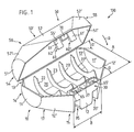
- FIG. 1 shows a perspective view and in a largely open position of a container designated as a whole by 100, which is designed to interchangeably accommodate an odor or disinfection body (color stick), not shown.
- the container 100 essentially comprises a shell body 10 and a closure lid 50 articulated thereon in a manner not shown in detail.
- a hanging or hanging hook 75 is arranged on the closure lid 50, by means of which the container 100, as in FIG 9 schematically shown, can be hung in a toilet bowl 150.
- the design of the individual elements 10, 50 and 75 is described below.
- the shell body 10 designed as a receiving element has an inner space 20 and essentially comprises two side walls 11, 11 ', a rear wall 14, a bottom 17 and an end wall 15.
- the two side walls 11, 11 ' are formed approximately as a semicircular disk, onto which the bottom 17 and the end wall 15 are formed on the bottom 17.
- the end wall 15 has an end wall section 12 arranged at a distance A parallel to the rear wall 14, and two end wall sections 12 ', 12''formed thereon and widening conically.
- the individual end wall section 12 'or 12'' is connected to the correspondingly assigned side wall 11 or 11'.
- In the interior 20 of the shell body 10 at least two, but in the illustrated embodiment four, spaced-apart support ribs 22, 22 'and 23, 23' are provided.
- the ribs 22, 22 'and 23, 23' are formed on the inside of the rear wall 14 and on the inside of the base 17 and thus form a unit. Furthermore, a shut-off device 30 can be seen in FIG. 1, which is arranged on the inside of the first end wall section 12 oriented parallel to the rear wall 14 and will be described in detail later.
- the cover part 50 ′ essentially comprises a rear wall 54, a basket part 56 arranged thereon and an end wall 55 arranged on the basket part 56.
- the two side walls 51, 51 ' are formed approximately as a semicircular disk, to which, as shown in FIG. 6, the rear wall 54, which is designed in the form of a profile cross section, and the basket lid part 56 and the end wall 55 are connected.
- the end wall 55 has a front wall section 52 which is oriented and inclined at a distance and essentially parallel to the rear wall 54, and two end wall sections 52 'and 52''which are integrally formed thereon and widen conically.
- the individual end wall section 52 'or 52'' is connected to the correspondingly assigned side wall 51 or 51'.
- the two approximately hook-shaped latching elements 60, 60 'each have a correspondingly designed latching device 65, 65' arranged on the inside of the shell body 10 and at the same time the closure plug 70 seals brought into engagement with the appropriately designed, siphon-like shut-off element 30.
- the distance A on the shell body 10 in FIG. 1 from the rear wall 14 to the front edge (not shown in more detail) of the end wall section 12 arranged at a parallel distance therefrom, and the width of the section 12 designated B are dimensioned such that the individual, end wall section 12 'or 12' 'which widens conically and adjoins the respective side wall 11 or 11' and is angled at an angle ⁇ with respect to the end wall section 12, the angle ⁇ being of the order of magnitude between 25 ° and Is 45 °.
- section 12 which is not described in any more detail, can be used to affix (emboss) a corresponding company logo (not shown).
- the basket part 56 is essentially made up of several at intervals 41 and 41' Longitudinal ribs 45, 45 'arranged to each other are formed, which are formed in the angled corner region 53, 53' as rib sections 44, 44 'on the corresponding side wall 51, 51'. In the central region, the longitudinal ribs 45, 45 'are formed by a web 46 oriented approximately transversely thereto divided.
- the web 46 connects the rear wall 54 to the central section 52 of the front wall 55 and serves on the one hand to fasten the hanging or hanging hook 75 and on the other hand to stabilize the entire basket part 56.
- the shell body 10 is shown in the middle area for better illustration of the shut-off member 30 in a partially broken-open state and two recesses 35, 35 ', which are arranged approximately at a distance from one another and can be seen, for the two latching elements 60, 60' which are partially visible in FIG.
- two chambers 33 and 34 essentially formed by wall parts 31, 31 ', 31'', 32, can be seen.
- One chamber 33 serves as a dilution chamber and communicates with the interior 20 of the shell body 10 via an opening 32'.
- the other chamber 34 serves as an overflow channel through which the liquid is dispensed in the direction of arrow Z after the upper edge (level height) of the central wall part 31 ′′, which has not been identified.
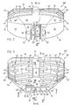
- FIG. 3 shows the container 100 in plan view and one can see the closure lid 50 designed as a basket part 56 with the longitudinal ribs 45, 45 'arranged at intervals 41, 41' to one another and formed on the web 46 in the central region, which with the lateral rib parts 44, 44 'are integrally formed on the correspondingly assigned side wall 51, 51'.
- Between the individual longitudinal ribs 45, 45 'are spaced-apart webs 42, 43 and 42', 43 ' which connect the longitudinal ribs 45, 45' to one another, by means of which a further stiffening of the basket part 56 is achieved.
- the closure cover 50 is shown partially broken open to better show the shut-off member 30 and the end wall section 12 can be seen with the conically widening parts arranged thereon Sections 12 'and 12''.
- the recesses 35, 35 'for the latching elements 60 and 60' and the chambers 33, 34 which are essentially separated from one another by correspondingly designed wall parts 31, 31 'and 31''are arranged between the two wall parts 19, 19' arranged at a distance from one another.
- the one chamber 33 designed as a dilution chamber is separated by the wall 31 ′′ from the chamber 34 designed as an overflow channel and preferably circular in cross section.
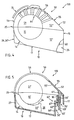
- FIG. 4 shows the container 100 shown in the closed position and in a side view and one recognizes the end wall 15, the bottom 17, the rear wall 14 of the shell body 10, the closure lid 50 articulated thereon with a schematically illustrated joint element 25 and the opening or opening arranged thereon Hooks 75. Furthermore, the rear wall 54, the basket part 56 with the rib sections 44 and the end wall 55 formed from the sections 52, 52 ', 52''can be seen. On the approximately circular arc-shaped rear wall 14 of the shell body 10, at least one contact part 26, but preferably two, in the longitudinal direction of the cup body 10 at a distance from one another (not shown) are provided, which are designed in profile cross section [-shaped and on the Back wall 14 are formed.
- FIG. 5 shows the container 100 along the line V - V in FIG. 3 in a sectional view and one recognizes it partially shown rib 22 ', the with the bottom 17 inclined with respect to the wall 27 of the bearing part 26', the locking device 65 'and the locking element 60' engaged therewith.
- the latching device 65 with the individual elements and the latching element 60 with the individual elements are designed analogously to the latching element 60 'described above and the latching device 65', with the cut profile (line V - V in FIG. 3), the details of a locking device 60 'have been described.
- the latching device 65 'formed on the bottom 17 of the shell body 10 has a wall 66' oriented approximately perpendicularly thereto and a shoulder 67 'connecting the two walls 66' and 18 to one another.
- the locking element 60 'arranged on the inside 55' of the end wall 55 has a first web 61 ', a locking cam 62' formed thereon and provided with an oblique edge (not designated), a second web 63 'and a stiffening rib 64'.
- the two latching elements 60, 60 ' are deflected accordingly when the latching cams 62, 62' contact the wall part 18 and then by the resilient restoring force of the latching element 60, 60 ', as in FIG 5, positively engaged with the shoulder 67, 67 'of the respective latching device 65, 65'.
- the two recesses 35, 35 'and the latching elements 60, 60' are designed such that the two latching elements 60, 60 'can be released with the finger (not shown) without further aids.
- the finger is inserted into the gap 36 'between the wall 66' and the second web 63 '.
- the detent elements 60, 60 ' can be released individually or together (both detent elements simultaneously).
- FIG. 6 shows the container 100 shown in a sectional view along the line VI-VI in FIG. 2 and the closure cover 50 and the shell body 10 can be seen.
- the closure cover 50 articulated with the joint element 25 on the shell body 10 comprises the rear wall 54, which is of approximately circular arc shape, the basket part 56 adjoining it and formed from the longitudinal ribs 45 'arranged at intervals 41' from one another, and the end wall 55 adjoining it.
- On the inside 55 'of the End wall section 52 of the closure plug 70 is provided with a recess 71, which is arranged sealingly in the upper opening part 37 (FIG. 1) formed essentially from the chamber 33 and the overflow channel 34.
- FIG. 6 shows an arcuate section 14 'of the rear wall 14 and the base 17 formed thereon.
- the floor 17 has a first base section 17' which is inclined with respect to the rear wall section 14 'and a second, adjoining bottom section 17 ′′, which is formed at the other end orthogonally on the end wall section 12.
- the wall 18 is arranged with the latching devices 65, 65 'arranged at a distance from one another.
- the opening 32 ′ is provided in the wall 18, through which the overflow chamber 33 is connected to the interior 20 of the shell body 10.
- FIG. 7 shows a section of the container 100 according to the line VII-VII in FIG. 3 in a sectional view, and the sealing cover 50, the shell body 10 and the overflow channel 34 of the shut-off element 30 can be seen.
- the overflow channel 34 is extended in the lower region Outlet spout 34 'provided.
- the ribs 22, 22 'and 23, 23 '(FIG. 1) are each provided with a support surface which is designed in accordance with the odor or disinfection block (not shown) to be stored thereon. 5, 6 and 7, the ribs 22 'and 23' are shown partially broken off, which in this exemplary embodiment are each provided with an arc-shaped support surface 24.
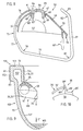
- the closure cover 50 shows the closure cover 50 shown in a sectional view as well as the hanging and hanging hook 75 arranged thereon and one recognizes the web 46 of the closure cover 50, which is partially circular in shape and shown in section.
- the recess 47 is arranged in the upper region of the web 46, to which two inwardly directed webs 48 and 48 'are formed.
- The, for example, one-piece hook-on and hook-in hook 75 comprises a clamping element 85 and a plurality of sections 76, 77, 79, 81 and 83, which are connected to one another by curved parts 78, 80 and 82, which are designed as articulated points (not shown), the clamping element 85 being connected via a recess 84 is connected to the section 76.
- the recess 84 and the individual arc parts 78, 80 and 82 are designed such that the individual sections 76, 77, 79, 81 and 83, as shown schematically in FIG. 9, optimally fit the respective plant part of the correspondingly designed toilet bowl rim 155 adjust.
- the clamping element 85 formed on the hanging and hanging hook 75 has two latching cams 87, 87 'which are connected to one another by a web 86 and which, with correspondingly integrally formed latching cams 88, 88', can be brought into spring-elastic engagement with the webs 48, 48 '.
- FIG. 10 shows, as a further exemplary embodiment, the portion of a suspension hook 75 ′ designated by a circle K in FIG.
- the suspension hook 75 ' is essentially constructed analogously to the suspension hook 75 and the first section 76' and a snap on the closure cover 50 can be seen attached clamping element 85 '.
- an articulation point 90 is provided between the first section 76 'and the clamping element 85'.
- This predetermined articulation point 90 has a web 89 which is integrally formed on the clamping element 85 'and is directed approximately radially outwards, and an arch piece 89' which connects the first section 76 'to the web 89.
- the transition 89 ′′ from the first section 76 ′ to the web 89 is formed on the inside of the arch section 89 ′ in such a way that the unspecified wall of the arch section 89 ′ is smaller than the wall thickness of the first section 76 ′ and the web 89. This ensures optimal adaptation to the toilet bowl profile.
- FIG. 9 shows a section of a toilet bowl, shown schematically and in section, of a toilet bowl designated as a whole by 150, and a bowl section 151 and a bowl rim 155 formed from the sections 152, 153 and 154 with the flushing water channel 155 'can be seen.
- the container 100 suspended on the bowl edge 155 with the correspondingly designed sections of the hanging and hanging hook 75 is supported with the two contact parts 26, 26 'on the inside 151' of the toilet bowl 150.
- the container 100 is designed and arranged on the rim of the toilet bowl 155 in such a way that the water emerging from the nozzle 34 'of the overflow channel 34 in the direction of the arrow Z' and colored by the color stick (not shown) is led to the water level WS at a distance from the toilet bowl body .
Landscapes
- Public Health (AREA)
- Health & Medical Sciences (AREA)
- Epidemiology (AREA)
- Life Sciences & Earth Sciences (AREA)
- Engineering & Computer Science (AREA)
- Hydrology & Water Resources (AREA)
- Water Supply & Treatment (AREA)
- Closures For Containers (AREA)
- Bidet-Like Cleaning Device And Other Flush Toilet Accessories (AREA)
- Non-Flushing Toilets (AREA)
- Absorbent Articles And Supports Therefor (AREA)
- Details Of Rigid Or Semi-Rigid Containers (AREA)
- Chairs For Special Purposes, Such As Reclining Chairs (AREA)
- Stored Programmes (AREA)
- Percussion Or Vibration Massage (AREA)
- Carbon And Carbon Compounds (AREA)
- Sanitary Device For Flush Toilet (AREA)
Applications Claiming Priority (2)
| Application Number | Priority Date | Filing Date | Title |
|---|---|---|---|
| CH233090 | 1990-07-12 | ||
| CH2330/90 | 1990-07-12 |
Publications (2)
| Publication Number | Publication Date |
|---|---|
| EP0465975A1 EP0465975A1 (de) | 1992-01-15 |
| EP0465975B1 true EP0465975B1 (de) | 1994-09-28 |
Family
ID=4231295
Family Applications (1)
| Application Number | Title | Priority Date | Filing Date |
|---|---|---|---|
| EP91110854A Expired - Lifetime EP0465975B1 (de) | 1990-07-12 | 1991-07-01 | Vorrichtung zur Abgabe einer Substanz in eine WC-Schüssel |
Country Status (8)
| Country | Link |
|---|---|
| EP (1) | EP0465975B1 (da) |
| AT (1) | ATE112348T1 (da) |
| DE (1) | DE59103088D1 (da) |
| DK (1) | DK0465975T3 (da) |
| ES (1) | ES2063410T3 (da) |
| FI (1) | FI94979C (da) |
| NO (1) | NO912724L (da) |
| PT (1) | PT8754U (da) |
Cited By (1)
| Publication number | Priority date | Publication date | Assignee | Title |
|---|---|---|---|---|
| USD464107S1 (en) | 2002-01-17 | 2002-10-08 | S. C. Johnson & Son, Inc. | Dispenser housing |
Families Citing this family (3)
| Publication number | Priority date | Publication date | Assignee | Title |
|---|---|---|---|---|
| DE4428970A1 (de) * | 1994-08-16 | 1996-02-22 | Buck Chemie Gmbh | WC-Körbchen |
| US6311340B1 (en) * | 1997-11-11 | 2001-11-06 | S. C. Johnson & Son, Inc. | Dispensing device |
| DE102011001049A1 (de) * | 2011-03-03 | 2012-09-06 | Buck-Chemie Gmbh | Vorrichtung zur Abgabe von Toilettenmittel an das Spülwasser |
Family Cites Families (7)
| Publication number | Priority date | Publication date | Assignee | Title |
|---|---|---|---|---|
| GB2098253B (en) * | 1981-05-08 | 1985-07-03 | Oreal | Disinfecting water closet pans |
| CH651611A5 (en) * | 1981-06-03 | 1985-09-30 | Schwanden Kunststoff | Carrier, intended for introduction into a WC bowl, for substances to be added to the flushing water |
| EP0092283B1 (en) * | 1982-04-20 | 1988-03-16 | Unilever N.V. | Device for cleaning and/or colouring lavatory flush water |
| IT206983Z2 (it) * | 1986-01-29 | 1987-10-26 | Golden Arrow Co Zug | Gabbietta componibile per prodotti igienici per apparecchi sanitari. |
| GB2194258B (en) * | 1986-08-15 | 1990-11-21 | Jeyes Group Ltd | Lavatory cleansing devices |
| US4777670A (en) * | 1988-01-13 | 1988-10-18 | S. C. Johnson & Son, Inc. | Under-the-rim dispensing unit |
| FR2633259B1 (fr) * | 1988-06-28 | 1993-03-12 | Oreal | Support de produit, notamment colorant, destine a etre accroche sur le rebord d'une cuvette de toilettes |
-
1991
- 1991-07-01 DK DK91110854.6T patent/DK0465975T3/da not_active Application Discontinuation
- 1991-07-01 AT AT91110854T patent/ATE112348T1/de not_active IP Right Cessation
- 1991-07-01 ES ES91110854T patent/ES2063410T3/es not_active Expired - Lifetime
- 1991-07-01 EP EP91110854A patent/EP0465975B1/de not_active Expired - Lifetime
- 1991-07-01 DE DE59103088T patent/DE59103088D1/de not_active Expired - Fee Related
- 1991-07-10 FI FI913342A patent/FI94979C/fi active IP Right Grant
- 1991-07-11 NO NO91912724A patent/NO912724L/no not_active Application Discontinuation
-
1993
- 1993-04-23 PT PT8754U patent/PT8754U/pt not_active IP Right Cessation
Cited By (1)
| Publication number | Priority date | Publication date | Assignee | Title |
|---|---|---|---|---|
| USD464107S1 (en) | 2002-01-17 | 2002-10-08 | S. C. Johnson & Son, Inc. | Dispenser housing |
Also Published As
| Publication number | Publication date |
|---|---|
| DK0465975T3 (da) | 1995-03-13 |
| ATE112348T1 (de) | 1994-10-15 |
| FI94979C (fi) | 1995-11-27 |
| FI913342A0 (fi) | 1991-07-10 |
| PT8754T (pt) | 1994-01-31 |
| FI94979B (fi) | 1995-08-15 |
| ES2063410T3 (es) | 1995-01-01 |
| PT8754U (pt) | 1996-01-31 |
| DE59103088D1 (de) | 1994-11-03 |
| NO912724L (no) | 1992-01-13 |
| NO912724D0 (no) | 1991-07-11 |
| EP0465975A1 (de) | 1992-01-15 |
| FI913342A7 (fi) | 1992-01-13 |
Similar Documents
| Publication | Publication Date | Title |
|---|---|---|
| DE4023423C2 (de) | Verschlußanordnung für einen Behälter | |
| DE60026590T2 (de) | Flüssigkeitsspender | |
| CH662259A5 (de) | Streueinrichtung fuer aufnahme und abgabe einer wuerze. | |
| DE4221533A1 (de) | Gewuerzstreuer | |
| DE3217286C2 (da) | ||
| DE2104787B2 (de) | Scharnierteil | |
| DE3639537C2 (da) | ||
| DE2529169C2 (de) | Vorrichtung zur Verteilung von Spülwasser in einer Klosettschüssel | |
| DE2618151A1 (de) | Hebelverschluss | |
| DE69720764T2 (de) | Abgabevorrichtung | |
| EP0850762A1 (de) | Einsatz für einen Keilfarbkasten von Druckmaschinen | |
| DE2542038C2 (de) | Vorratsbehälter für ein streifenförmiges Abreißtuch | |
| DE3228415A1 (de) | Wischblatt aus kunststoff | |
| EP0154289B1 (de) | Vorrichtung zum Züchten von Pflanzen mit abnormalem Wachstum in einem Behälter | |
| DE3804894A1 (de) | Etikettenleiste | |
| EP0465975A1 (de) | Vorrichtung zur Abgabe einer Substanz in eine WC-Schüssel | |
| DE19540112A1 (de) | Gehäuse zur Installation, Isolierung und Einkapselung elektrischer, elektronischer und pneumatischer Geräte und Vorrichtungen | |
| DE69807087T2 (de) | Reinigungs- und erfrischungsvorrichtung zum einhängen am rand eines toilettenbeckens | |
| DE3490325T1 (de) | Scheibenwischer mit Wischergelenkachse am Arm mit Querverriegelung | |
| DE2721348C2 (de) | Halterung für WC-Desodorantien | |
| EP3716758B1 (de) | Tiertränke, insbesondere für schnabeltiere | |
| DE60114106T2 (de) | Säuberungs- und Deodorierungsvorrichtung für eine Toilettenschüssel | |
| DE29607073U1 (de) | Gutaufnahmebehälter | |
| DE3014061C2 (da) | ||
| DE2742657C2 (da) |
Legal Events
| Date | Code | Title | Description |
|---|---|---|---|
| PUAI | Public reference made under article 153(3) epc to a published international application that has entered the european phase |
Free format text: ORIGINAL CODE: 0009012 |
|
| AK | Designated contracting states |
Kind code of ref document: A1 Designated state(s): AT BE CH DE DK ES FR GB IT LI NL SE |
|
| 17P | Request for examination filed |
Effective date: 19920619 |
|
| 17Q | First examination report despatched |
Effective date: 19921014 |
|
| RAP3 | Party data changed (applicant data changed or rights of an application transferred) |
Owner name: UNILEVER PLC Owner name: UNILEVER N.V. |
|
| GRAA | (expected) grant |
Free format text: ORIGINAL CODE: 0009210 |
|
| AK | Designated contracting states |
Kind code of ref document: B1 Designated state(s): AT BE CH DE DK ES FR GB IT LI NL SE |
|
| REF | Corresponds to: |
Ref document number: 112348 Country of ref document: AT Date of ref document: 19941015 Kind code of ref document: T |
|
| REF | Corresponds to: |
Ref document number: 59103088 Country of ref document: DE Date of ref document: 19941103 |
|
| GBT | Gb: translation of ep patent filed (gb section 77(6)(a)/1977) |
Effective date: 19941019 |
|
| ET | Fr: translation filed | ||
| ITF | It: translation for a ep patent filed | ||
| REG | Reference to a national code |
Ref country code: ES Ref legal event code: FG2A Ref document number: 2063410 Country of ref document: ES Kind code of ref document: T3 |
|
| EAL | Se: european patent in force in sweden |
Ref document number: 91110854.6 |
|
| REG | Reference to a national code |
Ref country code: DK Ref legal event code: T3 |
|
| PLBE | No opposition filed within time limit |
Free format text: ORIGINAL CODE: 0009261 |
|
| 26N | No opposition filed | ||
| PGFP | Annual fee paid to national office [announced via postgrant information from national office to epo] |
Ref country code: CH Payment date: 19960702 Year of fee payment: 6 |
|
| PG25 | Lapsed in a contracting state [announced via postgrant information from national office to epo] |
Ref country code: LI Free format text: LAPSE BECAUSE OF NON-PAYMENT OF DUE FEES Effective date: 19970731 Ref country code: CH Free format text: LAPSE BECAUSE OF NON-PAYMENT OF DUE FEES Effective date: 19970731 |
|
| REG | Reference to a national code |
Ref country code: CH Ref legal event code: PL |
|
| PGFP | Annual fee paid to national office [announced via postgrant information from national office to epo] |
Ref country code: AT Payment date: 20000612 Year of fee payment: 10 |
|
| PGFP | Annual fee paid to national office [announced via postgrant information from national office to epo] |
Ref country code: DK Payment date: 20000613 Year of fee payment: 10 |
|
| PGFP | Annual fee paid to national office [announced via postgrant information from national office to epo] |
Ref country code: SE Payment date: 20000620 Year of fee payment: 10 |
|
| PGFP | Annual fee paid to national office [announced via postgrant information from national office to epo] |
Ref country code: FR Payment date: 20000621 Year of fee payment: 10 |
|
| PGFP | Annual fee paid to national office [announced via postgrant information from national office to epo] |
Ref country code: GB Payment date: 20000627 Year of fee payment: 10 |
|
| PGFP | Annual fee paid to national office [announced via postgrant information from national office to epo] |
Ref country code: DE Payment date: 20000629 Year of fee payment: 10 |
|
| PGFP | Annual fee paid to national office [announced via postgrant information from national office to epo] |
Ref country code: BE Payment date: 20000704 Year of fee payment: 10 |
|
| PGFP | Annual fee paid to national office [announced via postgrant information from national office to epo] |
Ref country code: NL Payment date: 20000713 Year of fee payment: 10 |
|
| PGFP | Annual fee paid to national office [announced via postgrant information from national office to epo] |
Ref country code: ES Payment date: 20000721 Year of fee payment: 10 |
|
| PG25 | Lapsed in a contracting state [announced via postgrant information from national office to epo] |
Ref country code: GB Free format text: LAPSE BECAUSE OF NON-PAYMENT OF DUE FEES Effective date: 20010701 Ref country code: DK Free format text: LAPSE BECAUSE OF NON-PAYMENT OF DUE FEES Effective date: 20010701 Ref country code: AT Free format text: LAPSE BECAUSE OF NON-PAYMENT OF DUE FEES Effective date: 20010701 |
|
| PG25 | Lapsed in a contracting state [announced via postgrant information from national office to epo] |
Ref country code: SE Free format text: LAPSE BECAUSE OF NON-PAYMENT OF DUE FEES Effective date: 20010702 Ref country code: ES Free format text: LAPSE BECAUSE OF NON-PAYMENT OF DUE FEES Effective date: 20010702 |
|
| PG25 | Lapsed in a contracting state [announced via postgrant information from national office to epo] |
Ref country code: BE Free format text: LAPSE BECAUSE OF NON-PAYMENT OF DUE FEES Effective date: 20010731 |
|
| BERE | Be: lapsed |
Owner name: UNILEVER N.V. Effective date: 20010731 |
|
| PG25 | Lapsed in a contracting state [announced via postgrant information from national office to epo] |
Ref country code: NL Free format text: LAPSE BECAUSE OF NON-PAYMENT OF DUE FEES Effective date: 20020201 |
|
| GBPC | Gb: european patent ceased through non-payment of renewal fee |
Effective date: 20010701 |
|
| EUG | Se: european patent has lapsed |
Ref document number: 91110854.6 |
|
| REG | Reference to a national code |
Ref country code: DK Ref legal event code: EBP |
|
| PG25 | Lapsed in a contracting state [announced via postgrant information from national office to epo] |
Ref country code: FR Free format text: LAPSE BECAUSE OF NON-PAYMENT OF DUE FEES Effective date: 20020329 |
|
| NLV4 | Nl: lapsed or anulled due to non-payment of the annual fee |
Effective date: 20020201 |
|
| PG25 | Lapsed in a contracting state [announced via postgrant information from national office to epo] |
Ref country code: DE Free format text: LAPSE BECAUSE OF NON-PAYMENT OF DUE FEES Effective date: 20020501 |
|
| REG | Reference to a national code |
Ref country code: FR Ref legal event code: ST |
|
| REG | Reference to a national code |
Ref country code: ES Ref legal event code: FD2A Effective date: 20020810 |
|
| PG25 | Lapsed in a contracting state [announced via postgrant information from national office to epo] |
Ref country code: IT Free format text: LAPSE BECAUSE OF NON-PAYMENT OF DUE FEES;WARNING: LAPSES OF ITALIAN PATENTS WITH EFFECTIVE DATE BEFORE 2007 MAY HAVE OCCURRED AT ANY TIME BEFORE 2007. THE CORRECT EFFECTIVE DATE MAY BE DIFFERENT FROM THE ONE RECORDED. Effective date: 20050701 |