EP0465995A1 - Spring catch with triggering member - Google Patents
Spring catch with triggering member Download PDFInfo
- Publication number
- EP0465995A1 EP0465995A1 EP91110949A EP91110949A EP0465995A1 EP 0465995 A1 EP0465995 A1 EP 0465995A1 EP 91110949 A EP91110949 A EP 91110949A EP 91110949 A EP91110949 A EP 91110949A EP 0465995 A1 EP0465995 A1 EP 0465995A1
- Authority
- EP
- European Patent Office
- Prior art keywords
- spring catch
- triggering
- spring
- catch
- lever
- Prior art date
- Legal status (The legal status is an assumption and is not a legal conclusion. Google has not performed a legal analysis and makes no representation as to the accuracy of the status listed.)
- Withdrawn
Links
Images

Classifications
-
- F—MECHANICAL ENGINEERING; LIGHTING; HEATING; WEAPONS; BLASTING
- F16—ENGINEERING ELEMENTS AND UNITS; GENERAL MEASURES FOR PRODUCING AND MAINTAINING EFFECTIVE FUNCTIONING OF MACHINES OR INSTALLATIONS; THERMAL INSULATION IN GENERAL
- F16B—DEVICES FOR FASTENING OR SECURING CONSTRUCTIONAL ELEMENTS OR MACHINE PARTS TOGETHER, e.g. NAILS, BOLTS, CIRCLIPS, CLAMPS, CLIPS OR WEDGES; JOINTS OR JOINTING
- F16B45/00—Hooks; Eyes
- F16B45/04—Hooks with sliding closing member
- F16B45/049—Hooks with sliding closing member provided with means biasing the closing member
Definitions
- the present invention relates to a spring catch having a new design in which the position of a closing member is controlled by the action of a triggering member which is actuated upon the insertion of a rigid element to which the catch is to be coupled.
- Spring catches conventionally consist of a body in the form of a C-shaped bar, having a closing lever pivotably hinged at one end of the C-shaped body; the lever is biased by a spring so as to engage with the other end of the abovemen- tioned body.
- conventional catches may be provided with locking or securing device which prevent accidental or undesired opening of the closing lever.
- Spring catches of this kind are described for example in European Patent Application No. 318742 of the Applicant and in European Patent No. 289490; other examples may be found in US Patent No. 4401333 and in French Patent Application No. 2476249.
- Spring catches are also known, in which the closing element is in the form of a sliding member which is biased in the closed position by a spring and which must be manually pulled with a finger in order to open the catch.
- the object of the present invention is to provide a spring catch with a completely new design which overcomes the drawbacks or the applicational limitations of conventional spring catches, in that it allows the frontal insertion of the spring catch into the eyelet of a nail or the engagement to an outer member to which the catch must be coupled, using the same insertion movement in order to trigger a closing member.
- a further object of the present invention is to provide a spring catch as referred to above, whereby it is no longer necessary to use the hand to keep the catch open, thus enabling the catch to be held more firmly and more securely during use.
- a spring catch which is characterized by comprising a slidable closing member controlled by triggering member which is opposite to the inlet aperture of the catch and is actuated by the frontal insertion of an outer member through the inlet aperture of the catch itself.
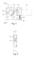
- the spring catch according to the invention substantially comprises a rigid body 10 in the general shape of a C body, having a central opening 11 which communicates with a front inlet aperture 12 across which there passes a pin or other slidable closing member 13.
- a pin or other slidable closing member 13 On the side of the body 10 opposite to the inlet aperture 12 there is an eyelet 14 or transverse opening suitable for receiving a strap, cord or other element 15 designed for coupling or supporting a load as well as for manual gripping, as shown.
- the closing pin 13 for the inlet aperture 12 of the spring catch slides transversely with respect to the inlet itself inside a guide hole 16 formed transversely with respect to the opposed front ends of the C-shaped body of the spring catch, which, as shown, are provided with the slanted guiding surfaces converging in the direction of the aperture 12.
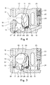
- the pin 13 has at its bottom end in Figure 3 an elongated eyelet 17 by means of which said pin is linked to a spigot 18 protruding from a manually operable control member in the form of a lever 19 pivotably hinged to the body 10 at the point 20.
- the lever 19 is provided inside a cavity or seat 21 which opens out both on the outer side and on the inner side towards the central opening 11 of the spring catch.
- the control lever 19 with its rear end protrudes a short distance from the body 10 of the spring catch and is subject to the biasing action of an elastic counter-force exerted by a spring 22 situated inside a seating 23; the counter spring 22 acts indirectly on the end of the lever 19 via a sliding pin 24 which projects from the seating 23, parallel to the closing pin 13 of the spring catch, extending so as to make contact against the ab- ovementioned lever 19.
- a plug 25 is screwed into the seat 23 of the spring so as to form a rear abutment for the spring 22.
- the hand lever 19 and hence the position of the closing pin 13 is controlled by a triggering member 26 able to engage with and disengage from the operating lever 19 by rotation.
- This triggering member 26 is in the form of a lever or trigger pivotably hinged at 27 to the body 10 and on one side extends inside the central opening 11 of the spring catch, being positioned opposite to the front inlet aperture 12, while on the other side it extends inside the seat 21, towards the lever 19, so as to engage with the latter.
- the bottom end of the trigger 26 has a step shaped projection 28 by means of which it engage a corresponding projection or step portion 29 of the control lever 19 as clearly shown in Figure 4.
- a spring 30 acts on the trigger 26 so as to keep it in the engaged condition of Figure 4 where it prevents rotation of the control lever 19, in the open position of the spring catch shown in Figure 4.
- the mode of operation of the spring catch described is as follows: by pressing the lever 19, acting with a finger on the protruding end to rotate the same in the counterclock direction, the spring catch is opened, by simultaneously tensioning the spring 22 and cocking the trigger 26 which, as a result of the action of the spring 30, rotates from the position shown in Figure 3 in which the lower end of the trigger protrudes into a cavity of the lever 19, to the position in Figure 4, in which the stepped end 28 of the trigger 26 engages the lever 19 preventing its rotation to keep the catch in the open condition shown.
- the spring catch is held between two finger, that is the thumb and the forefinger of a hand holding fast with the palm the gripping element 15 which, can be held firmly such that the maximum grip can be exerted with the hand, the spring catch already being open and ready to snap into the closed position.
- Figure 5 shows a further embodiment of the triggering member of the spring catch.
- parts which are similar or operationally equivalent to those shown in the previous figures have been denoted by the same reference numbers.
- the trigger 26 is elastically biased by a coil spring 30 inside the seat 21 housing the lever 19 and the trigger 26.
- the trigger 26 engages moreover with the sliding member 13 by means of a strip or spigot 32 linked with the trigger 26 at 32'.
- the strip or spigot 32 slides inside a bore 33 perpendicular to the hole 16, engaging with its front end in a transverse slot 34 in the closing member 13.
Landscapes
- Engineering & Computer Science (AREA)
- General Engineering & Computer Science (AREA)
- Mechanical Engineering (AREA)
- Hooks, Suction Cups, And Attachment By Adhesive Means (AREA)
- Load-Engaging Elements For Cranes (AREA)
- Manufacturing Of Micro-Capsules (AREA)
- Agricultural Chemicals And Associated Chemicals (AREA)
- Pharmaceuticals Containing Other Organic And Inorganic Compounds (AREA)
Applications Claiming Priority (2)
| Application Number | Priority Date | Filing Date | Title |
|---|---|---|---|
| IT2092290 | 1990-07-12 | ||
| IT02092290A IT1246765B (it) | 1990-07-12 | 1990-07-12 | Moschettone con organo di chiusura a scatto. |
Publications (1)
| Publication Number | Publication Date |
|---|---|
| EP0465995A1 true EP0465995A1 (en) | 1992-01-15 |
Family
ID=11174125
Family Applications (1)
| Application Number | Title | Priority Date | Filing Date |
|---|---|---|---|
| EP91110949A Withdrawn EP0465995A1 (en) | 1990-07-12 | 1991-07-02 | Spring catch with triggering member |
Country Status (3)
| Country | Link |
|---|---|
| EP (1) | EP0465995A1 (it) |
| JP (1) | JPH04249611A (it) |
| IT (1) | IT1246765B (it) |
Cited By (2)
| Publication number | Priority date | Publication date | Assignee | Title |
|---|---|---|---|---|
| EP0974760A1 (en) * | 1998-07-22 | 2000-01-26 | KONG S.p.A. | Connector with snap closure |
| GB2541364A (en) * | 2015-07-06 | 2017-02-22 | Pickersgill Frank | Quick release shackle |
Families Citing this family (1)
| Publication number | Priority date | Publication date | Assignee | Title |
|---|---|---|---|---|
| JP5149563B2 (ja) * | 2006-08-25 | 2013-02-20 | 株式会社イング | 吊り具 |
Citations (3)
| Publication number | Priority date | Publication date | Assignee | Title |
|---|---|---|---|---|
| US2577790A (en) * | 1946-06-28 | 1951-12-11 | William E Mccormick | Positive-locking hook |
| GB1328849A (en) * | 1970-12-30 | 1973-09-05 | Access Quipment Ltd | Connecting means |
| GB2001384A (en) * | 1977-07-21 | 1979-01-31 | Henssgen Karabinerhaken Gmbh | Spring safety hooks |
-
1990
- 1990-07-12 IT IT02092290A patent/IT1246765B/it active IP Right Grant
-
1991
- 1991-07-02 EP EP91110949A patent/EP0465995A1/en not_active Withdrawn
- 1991-07-12 JP JP3172637A patent/JPH04249611A/ja active Pending
Patent Citations (3)
| Publication number | Priority date | Publication date | Assignee | Title |
|---|---|---|---|---|
| US2577790A (en) * | 1946-06-28 | 1951-12-11 | William E Mccormick | Positive-locking hook |
| GB1328849A (en) * | 1970-12-30 | 1973-09-05 | Access Quipment Ltd | Connecting means |
| GB2001384A (en) * | 1977-07-21 | 1979-01-31 | Henssgen Karabinerhaken Gmbh | Spring safety hooks |
Cited By (3)
| Publication number | Priority date | Publication date | Assignee | Title |
|---|---|---|---|---|
| EP0974760A1 (en) * | 1998-07-22 | 2000-01-26 | KONG S.p.A. | Connector with snap closure |
| US6237201B1 (en) | 1998-07-22 | 2001-05-29 | Kong S.P.A. | Connector with snap closure |
| GB2541364A (en) * | 2015-07-06 | 2017-02-22 | Pickersgill Frank | Quick release shackle |
Also Published As
| Publication number | Publication date |
|---|---|
| IT9020922A1 (it) | 1992-01-12 |
| IT9020922A0 (it) | 1990-07-12 |
| JPH04249611A (ja) | 1992-09-04 |
| IT1246765B (it) | 1994-11-26 |
Similar Documents
| Publication | Publication Date | Title |
|---|---|---|
| US2551913A (en) | Retainer latch for pistol holsters | |
| US6161290A (en) | Utility knife | |
| US6941661B2 (en) | Folding knife | |
| KR100208304B1 (ko) | 두개의 부품을 위한 이중 분배 카트리지용 수동 조작 분배 장치 | |
| CA2027784C (en) | Double locking snap hook | |
| US7160138B2 (en) | Package with lock mechanism | |
| US5832573A (en) | Quick release buckle assembly | |
| US4164225A (en) | Surgical suturing instrument | |
| US6553672B2 (en) | Folding knife with compression locking mechanism | |
| US20120159789A9 (en) | Folding knife | |
| JPH0763406B2 (ja) | バックルのばね負荷される摺動バーウェブコネクタ組立体 | |
| EP0093458B1 (fr) | Dispositif de fermeture d'une chaussure de sport | |
| US9078604B2 (en) | Lancing devices | |
| EP0465995A1 (en) | Spring catch with triggering member | |
| US4612907A (en) | Archery release aid | |
| US7360285B2 (en) | Automatic slider for a slide fastener | |
| US7093330B2 (en) | Snap-hook tether | |
| US5690665A (en) | Rotatable ear piercing cartridge assembly | |
| JP3652766B2 (ja) | バックル | |
| CA2201450C (en) | A fishing lure retriever | |
| US2470941A (en) | Fish stringer | |
| US3427103A (en) | Shutter release device for moving picture cameras | |
| GB2189287A (en) | Connecting means for scaffolding components and the like | |
| WO1998020761A1 (en) | A quick release buckle assembly | |
| JP3774004B2 (ja) | ドアガード |
Legal Events
| Date | Code | Title | Description |
|---|---|---|---|
| PUAI | Public reference made under article 153(3) epc to a published international application that has entered the european phase |
Free format text: ORIGINAL CODE: 0009012 |
|
| AK | Designated contracting states |
Kind code of ref document: A1 Designated state(s): AT CH DE ES FR GB LI |
|
| STAA | Information on the status of an ep patent application or granted ep patent |
Free format text: STATUS: THE APPLICATION IS DEEMED TO BE WITHDRAWN |
|
| 18D | Application deemed to be withdrawn |
Effective date: 19920716 |