EP0466058A1 - Appareil de reproduction et d'enregistrement optique de données - Google Patents
Appareil de reproduction et d'enregistrement optique de données Download PDFInfo
- Publication number
- EP0466058A1 EP0466058A1 EP91111253A EP91111253A EP0466058A1 EP 0466058 A1 EP0466058 A1 EP 0466058A1 EP 91111253 A EP91111253 A EP 91111253A EP 91111253 A EP91111253 A EP 91111253A EP 0466058 A1 EP0466058 A1 EP 0466058A1
- Authority
- EP
- European Patent Office
- Prior art keywords
- optical arrangement
- sit
- photodetector
- light
- photodetectors
- Prior art date
- Legal status (The legal status is an assumption and is not a legal conclusion. Google has not performed a legal analysis and makes no representation as to the accuracy of the status listed.)
- Withdrawn
Links
- 230000003287 optical effect Effects 0.000 title claims abstract description 26
- 230000000694 effects Effects 0.000 claims abstract description 9
- 230000035945 sensitivity Effects 0.000 claims description 3
- 230000003595 spectral effect Effects 0.000 claims description 3
- 230000007704 transition Effects 0.000 abstract description 6
- 150000003623 transition metal compounds Chemical class 0.000 abstract description 3
- 230000001678 irradiating effect Effects 0.000 abstract 1
- 230000037430 deletion Effects 0.000 description 2
- 238000012217 deletion Methods 0.000 description 2
- 230000003760 hair shine Effects 0.000 description 1
Images



Classifications
-
- G—PHYSICS
- G11—INFORMATION STORAGE
- G11B—INFORMATION STORAGE BASED ON RELATIVE MOVEMENT BETWEEN RECORD CARRIER AND TRANSDUCER
- G11B7/00—Recording or reproducing by optical means, e.g. recording using a thermal beam of optical radiation by modifying optical properties or the physical structure, reproducing using an optical beam at lower power by sensing optical properties; Record carriers therefor
-
- G—PHYSICS
- G11—INFORMATION STORAGE
- G11B—INFORMATION STORAGE BASED ON RELATIVE MOVEMENT BETWEEN RECORD CARRIER AND TRANSDUCER
- G11B7/00—Recording or reproducing by optical means, e.g. recording using a thermal beam of optical radiation by modifying optical properties or the physical structure, reproducing using an optical beam at lower power by sensing optical properties; Record carriers therefor
- G11B7/12—Heads, e.g. forming of the optical beam spot or modulation of the optical beam
- G11B7/125—Optical beam sources therefor, e.g. laser control circuitry specially adapted for optical storage devices; Modulators, e.g. means for controlling the size or intensity of optical spots or optical traces
- G11B7/127—Lasers; Multiple laser arrays
-
- G—PHYSICS
- G11—INFORMATION STORAGE
- G11B—INFORMATION STORAGE BASED ON RELATIVE MOVEMENT BETWEEN RECORD CARRIER AND TRANSDUCER
- G11B7/00—Recording or reproducing by optical means, e.g. recording using a thermal beam of optical radiation by modifying optical properties or the physical structure, reproducing using an optical beam at lower power by sensing optical properties; Record carriers therefor
- G11B7/004—Recording, reproducing or erasing methods; Read, write or erase circuits therefor
-
- G—PHYSICS
- G11—INFORMATION STORAGE
- G11B—INFORMATION STORAGE BASED ON RELATIVE MOVEMENT BETWEEN RECORD CARRIER AND TRANSDUCER
- G11B7/00—Recording or reproducing by optical means, e.g. recording using a thermal beam of optical radiation by modifying optical properties or the physical structure, reproducing using an optical beam at lower power by sensing optical properties; Record carriers therefor
- G11B7/12—Heads, e.g. forming of the optical beam spot or modulation of the optical beam
- G11B7/13—Optical detectors therefor
- G11B7/131—Arrangement of detectors in a multiple array
Definitions
- the invention relates to a device for optically reading and recording data using the Liesst effect, in which a light beam from a light source which is provided at the input of an optical arrangement focuses on a recording medium by means of the optical arrangement and from the recording medium to one at the output the optical arrangement provided photodetector is reflected.
- the Liesst effect - the abbreviation for Light Induced Excited Spin State Trapping - that is observed for transition metal compounds means the change in the spin state depending on the temperature. During the transition from low temperature to high temperature, the low spin state changes to the high spin state at a critical temperature, which is associated with a sudden characteristic color change in many transition metal compounds.
- this change in the spin state associated with a color change can also be achieved by irradiation with light.
- the color change can also be reversed by irradiation with light of a suitable wavelength.
- the object of the invention is to provide a simple device for optically recording and reading data for a recording medium, which shows the Liesst effect.
- the invention solves this problem in that one of several light sources of different wavelengths can optionally be positioned in front of the input of the optical arrangement so that light of different wavelengths can be emitted onto the recording medium for reading, recording or deleting data.
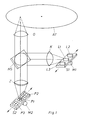
- the light beam from a light source L1 radiates through a collimator lens K onto a semitransparent mirror HS, which deflects the light beam at right angles to an objective lens O, which focuses it on a recording medium AT. From the recording medium AT, which shows the Liesst effect mentioned at the outset, the light beam is reflected back through the objective lens O to the semi-transparent mirror HS, which it shines through in a straight line in order to be focused by a cylindrical lens Z on a photodetector.
- a rail S1 is provided, on which three lasers L1, L2 and L3 are seated as light sources, the light of different wavelengths produce.
- the rail S1 can be moved in the direction of the arrow by means of a stepping motor M1, so that each of the three lasers L1, L2 and L3 can be positioned at the focal point of the collimator lens K.
- three photodetectors P1, P2 and P3 of different spectral sensitivity are arranged on a rail S2, which can be displaced in the direction of the arrow by a stepping motor M2, so that each photodetector can be positioned in the focal point of the cylindrical lens Z.
- the laser L1 and the photodetector P1 serve e.g. for reading the data.
- the laser L2 is shifted into the focal point of the collimator lens K and the photodetector P2 is shifted into the focal point of the cylindrical lens Z.
- the deletion of the data can be monitored by means of the photodetector P2.
- the laser L2 causes a transition from a spin state in the record carrier AT, e.g. the high spin state, in the other spin state, the low spin state.
- the laser L3 is pushed into the focal point of the collimator lens K by means of the rail S1 and the stepping motor M1, while at the same time the photodetector P3 is positioned at the focal point of the cylindrical lens Z by means of the rail S2 and the stepping motor F2.
- the recording of the data can be monitored with the aid of the photodetector P3.
- the spectral sensitivity of the three photodetectors P1, P2 and P3 is matched to the wavelengths of the three lasers L1, L2 and L3. If the deletion and recording of data is not monitored, a photodetector is sufficient.
- one of the two stepper motors is omitted because the rail S1 is mechanically coupled to the rail S2 by means of an angle W. Therefore, if one rail is moved, the other rail is also moved.
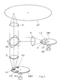
- the lasers L1, L2 and L3 can, as a third exemplary embodiment in FIG. 3 shows, be arranged on a disk SB1.
- the photodetectors P1, P2 and P3 can sit on a disc SB2.
- Each disc can e.g. are driven by a stepper motor M1 and M2.
- the two discs can also be mechanically e.g. be coupled to each other by means of a belt so that rotation of one disc also causes rotation of the other disc.
- the lasers L1, L2 and L3 and the photodetectors P1, P2 and P3 can be attached to a common drum TR, as is provided in a fourth exemplary embodiment, which is shown in FIG. 4.
- a common drum TR By rotating the drum TR, e.g. by means of a stepping motor M1, the lasers and the photodetectors are positioned in the focal point of the collimator lens K and the cylindrical lens Z.
- each laser L1, L2 and L3 is attached to the end of a swivel arm S1, S2 and S3.
- Each photodetector P1, P2 and P3 is also arranged at the end of a swivel arm S4, S5 and S6.
- Each swivel arm can be swiveled so that the laser or photodetector sitting on it can be swiveled into the focal point of the collimator or cylinder lens.
- the lasers L1, L2 and L3 sit on a disc SB1, while the photodetectors P1, P2 and P3 are on the inside of a cut-open drum TR which is mechanically connected to the disc SB1.
- a stepping motor M1 By rotating the disc SB1 by means of a stepping motor M1, both the lasers and the photodetectors are therefore simultaneously positioned in the focal points.
- This sixth exemplary embodiment is shown in FIG. 6.
- the invention is suitable for recording and reproducing devices which, using the Liesst effect, optically read data from a recording medium and record it on the recording medium.
Landscapes
- Physics & Mathematics (AREA)
- Optics & Photonics (AREA)
- Optical Head (AREA)
- Optical Recording Or Reproduction (AREA)
Applications Claiming Priority (2)
| Application Number | Priority Date | Filing Date | Title |
|---|---|---|---|
| DE4022095A DE4022095A1 (de) | 1990-07-11 | 1990-07-11 | Vorrichtung zum optischen lesen und aufzeichnen von daten |
| DE4022095 | 1990-07-11 |
Publications (1)
| Publication Number | Publication Date |
|---|---|
| EP0466058A1 true EP0466058A1 (fr) | 1992-01-15 |
Family
ID=6410087
Family Applications (1)
| Application Number | Title | Priority Date | Filing Date |
|---|---|---|---|
| EP91111253A Withdrawn EP0466058A1 (fr) | 1990-07-11 | 1991-07-05 | Appareil de reproduction et d'enregistrement optique de données |
Country Status (5)
| Country | Link |
|---|---|
| EP (1) | EP0466058A1 (fr) |
| JP (1) | JP2846151B2 (fr) |
| KR (1) | KR100246512B1 (fr) |
| DE (1) | DE4022095A1 (fr) |
| HU (1) | HUT60057A (fr) |
Cited By (1)
| Publication number | Priority date | Publication date | Assignee | Title |
|---|---|---|---|---|
| CN108181239A (zh) * | 2018-02-07 | 2018-06-19 | 张哲夫 | 一种多通道荧光定量pcr仪的光学系统 |
Families Citing this family (2)
| Publication number | Priority date | Publication date | Assignee | Title |
|---|---|---|---|---|
| US5971704A (en) * | 1997-04-23 | 1999-10-26 | Toyo Pumps North America Corporation | Device for adjusting the running clearance of an impeller |
| DE202010011975U1 (de) | 2010-08-30 | 2011-12-01 | MAE Maschinen- u. Apparatebau Götzen GmbH | Greifkopf für Erfassungseinrichtungen zum Manipulieren von langen Werkstücken, Zu- und Abführvorrichtung für lange Werkstücke in eine und aus einer Bearbeitungsmaschine |
Citations (3)
| Publication number | Priority date | Publication date | Assignee | Title |
|---|---|---|---|---|
| US4720825A (en) * | 1984-02-06 | 1988-01-19 | Asahi Kogaku Kogyo Kabushiki Kaisha | Optical data reproducing devices having improved trick play capability |
| DE3741910A1 (de) * | 1986-12-10 | 1988-06-23 | Hitachi Ltd | Im wellenlaengen-multiplexbetrieb arbeitendes optisches aufzeichnungsgeraet |
| EP0353078A2 (fr) * | 1988-07-29 | 1990-01-31 | Quantex Corporation | Système de tourne-disque optique |
-
1990
- 1990-07-11 DE DE4022095A patent/DE4022095A1/de not_active Withdrawn
-
1991
- 1991-07-05 EP EP91111253A patent/EP0466058A1/fr not_active Withdrawn
- 1991-07-05 HU HU912276A patent/HUT60057A/hu unknown
- 1991-07-09 JP JP3167893A patent/JP2846151B2/ja not_active Expired - Fee Related
- 1991-07-11 KR KR1019910011747A patent/KR100246512B1/ko not_active Expired - Fee Related
Patent Citations (3)
| Publication number | Priority date | Publication date | Assignee | Title |
|---|---|---|---|---|
| US4720825A (en) * | 1984-02-06 | 1988-01-19 | Asahi Kogaku Kogyo Kabushiki Kaisha | Optical data reproducing devices having improved trick play capability |
| DE3741910A1 (de) * | 1986-12-10 | 1988-06-23 | Hitachi Ltd | Im wellenlaengen-multiplexbetrieb arbeitendes optisches aufzeichnungsgeraet |
| EP0353078A2 (fr) * | 1988-07-29 | 1990-01-31 | Quantex Corporation | Système de tourne-disque optique |
Cited By (2)
| Publication number | Priority date | Publication date | Assignee | Title |
|---|---|---|---|---|
| CN108181239A (zh) * | 2018-02-07 | 2018-06-19 | 张哲夫 | 一种多通道荧光定量pcr仪的光学系统 |
| CN108181239B (zh) * | 2018-02-07 | 2023-09-12 | 张哲夫 | 一种多通道荧光定量pcr仪的光学系统 |
Also Published As
| Publication number | Publication date |
|---|---|
| JPH04229426A (ja) | 1992-08-18 |
| HUT60057A (en) | 1992-07-28 |
| KR920003269A (ko) | 1992-02-29 |
| JP2846151B2 (ja) | 1999-01-13 |
| DE4022095A1 (de) | 1992-01-16 |
| KR100246512B1 (ko) | 2000-03-15 |
| HU912276D0 (en) | 1991-12-30 |
Similar Documents
| Publication | Publication Date | Title |
|---|---|---|
| DE4235348C2 (de) | Aufnahme/Wiedergabe-Vorrichtung für ein optisches Band | |
| DE69110534T2 (de) | Verfahren zur Regelung eines Aufzeichnungslaserstrahls. | |
| DE69632493T2 (de) | Optisches Abtastgerät und Identifizierungsgerät zum Identifizieren des Typs eines optischen Aufzeichnungsmediums | |
| DE69125543T2 (de) | Gerät für optische Platten | |
| DE3687274T2 (de) | Spurnachlaufverfahren fuer optische speicherplatte. | |
| DE69609902T2 (de) | Optische Abtastvorrichtung | |
| DE69630930T2 (de) | Optisches Plattengerät und optischer Kopf dafür | |
| DE69026958T2 (de) | Dreilaser optisches scheibensystem | |
| DE3731862C2 (fr) | ||
| DE69125533T2 (de) | Erhöhung der Speicherdichte von Informationsspeichermedien | |
| DE69110533T2 (de) | Optisches Plattenaufzeichnungsgerät. | |
| DE69132426T2 (de) | System zur Aufzeichnung/Wiedergabe von Information auf/von eine(r) aufzeichnungsfähige(n) optische(n) Platte | |
| DE2625359A1 (de) | Informationswiedergabegeraet | |
| DE69312527T2 (de) | Optischer Abtastkopf für optisches Wiedergabegerät | |
| DE3445751A1 (de) | Einrichtung zum halten mehrerer lichtstrahlen in vorbestimmten relativen lagen | |
| DE2503952C2 (de) | Vorrichtung zum Auslesen eines Aufzeichnungsträgers, auf dem Information in einer optisch auslesbaren Struktur angebracht ist | |
| DE2607705C3 (de) | Vorrichtung zur optischen Wiedergabe von auf einer Platte aufgezeichneten Informationen | |
| DE68917965T2 (de) | Fehlerdetektorvorrichtung für einen optischen Abtastkopf. | |
| DE69123192T2 (de) | Optischer Kopf für magnetooptisches Informationswiedergabegerät | |
| DE3546718C2 (fr) | ||
| CH678122A5 (fr) | ||
| DE3704630C2 (fr) | ||
| DE3887228T2 (de) | Verfahren und Gerät für optische Aufnahme und Wiedergabe. | |
| DE10210237A1 (de) | Objektivlinse für einen optischen Abnehmer | |
| DE69817893T2 (de) | Objektivlinse, Wiedergabegerät und Wiedergabemethode |
Legal Events
| Date | Code | Title | Description |
|---|---|---|---|
| PUAI | Public reference made under article 153(3) epc to a published international application that has entered the european phase |
Free format text: ORIGINAL CODE: 0009012 |
|
| AK | Designated contracting states |
Kind code of ref document: A1 Designated state(s): AT BE CH DE DK ES FR GB GR IT LI LU NL SE |
|
| 17P | Request for examination filed |
Effective date: 19920622 |
|
| STAA | Information on the status of an ep patent application or granted ep patent |
Free format text: STATUS: THE APPLICATION IS DEEMED TO BE WITHDRAWN |
|
| 18D | Application deemed to be withdrawn |
Effective date: 19940201 |