EP0466076A2 - Spiral groove face seal - Google Patents
Spiral groove face seal Download PDFInfo
- Publication number
- EP0466076A2 EP0466076A2 EP91111347A EP91111347A EP0466076A2 EP 0466076 A2 EP0466076 A2 EP 0466076A2 EP 91111347 A EP91111347 A EP 91111347A EP 91111347 A EP91111347 A EP 91111347A EP 0466076 A2 EP0466076 A2 EP 0466076A2
- Authority
- EP
- European Patent Office
- Prior art keywords
- sealing ring
- face seal
- sealing
- rotating
- recess
- Prior art date
- Legal status (The legal status is an assumption and is not a legal conclusion. Google has not performed a legal analysis and makes no representation as to the accuracy of the status listed.)
- Granted
Links
- 238000007789 sealing Methods 0.000 claims abstract description 162
- 239000012530 fluid Substances 0.000 claims abstract description 58
- 230000006872 improvement Effects 0.000 claims description 2
- 239000007787 solid Substances 0.000 description 15
- 230000009471 action Effects 0.000 description 8
- 230000002706 hydrostatic effect Effects 0.000 description 8
- 238000005086 pumping Methods 0.000 description 6
- 230000003247 decreasing effect Effects 0.000 description 4
- 230000000694 effects Effects 0.000 description 4
- 230000009467 reduction Effects 0.000 description 3
- 230000001771 impaired effect Effects 0.000 description 2
- 230000002411 adverse Effects 0.000 description 1
- 238000000034 method Methods 0.000 description 1
- 230000004048 modification Effects 0.000 description 1
- 238000012986 modification Methods 0.000 description 1
- 230000008569 process Effects 0.000 description 1
- 230000003746 surface roughness Effects 0.000 description 1
Images








Classifications
-
- F—MECHANICAL ENGINEERING; LIGHTING; HEATING; WEAPONS; BLASTING
- F16—ENGINEERING ELEMENTS AND UNITS; GENERAL MEASURES FOR PRODUCING AND MAINTAINING EFFECTIVE FUNCTIONING OF MACHINES OR INSTALLATIONS; THERMAL INSULATION IN GENERAL
- F16J—PISTONS; CYLINDERS; SEALINGS
- F16J15/00—Sealings
- F16J15/16—Sealings between relatively-moving surfaces
- F16J15/34—Sealings between relatively-moving surfaces with slip-ring pressed against a more or less radial face on one member
- F16J15/3404—Sealings between relatively-moving surfaces with slip-ring pressed against a more or less radial face on one member and characterised by parts or details relating to lubrication, cooling or venting of the seal
- F16J15/3408—Sealings between relatively-moving surfaces with slip-ring pressed against a more or less radial face on one member and characterised by parts or details relating to lubrication, cooling or venting of the seal at least one ring having an uneven slipping surface
- F16J15/3412—Sealings between relatively-moving surfaces with slip-ring pressed against a more or less radial face on one member and characterised by parts or details relating to lubrication, cooling or venting of the seal at least one ring having an uneven slipping surface with cavities
Definitions
- the present invention relates to a spiral groove face seal, and more particularly to a spiral groove face seal in which an end face of a rotating sealing ring rotatable with a rotating shaft and an end face of a stationary sealing ring facing the rotating sealing ring form sealing surfaces for restricting a fluid flow from a high pressure side to a low pressure side.
- a spiral groove face seal is used for sealing the space between a rotating shaft and housing thereof.
- the spiral groove face seal is incorporated in, for example, gas turbines or compressors which generate high pressure.
- the end face seal comprises two annular sealing rings facing with each other, one of which includes a spiral groove area having a plurality of spiral grooves and a dam area extending from the spiral groove area and having a flat surface, the other of which has a flat surface.
- the rotating sealing ring 3 includes a spiral groove area 35 having a plurality of spiral grooves 33 and a dam area 34 extending from the spiral groove area 35 and having a flat surface.
- the spiral grooves 33 serves to pump fluid (gas) inwardly
- the dam area 34 serves to restrict fluid flow pumped by the spiral grooves 33.
- the end face seal disclosed in U.S. Pat. No. 3,499,653 is a hydrostatic mechanical seal of the gap type so that the sealing surfaces become noncontact by hydrostatic forces from fluid pressure. Therefore, there is no problem in starting resistance at the time of starting. However, since the sealing surfaces become noncontact by hydrostatic force from fluid, fluid is leaked from the sealing surfaces having a certain gap when the machine incorporating the seal face is stopped.
- a spiral groove face seal having a stationary sealing ring and a rotating sealing ring with opposed radially extending sealing surfaces, the rotating sealing ring being in contact with the stationary sealing ring at at least a part of the sealing surfaces when the rotating sealing ring is stopped, the rotating ring being brought out of contact with the stationary sealing ring when the rotating sealing ring is rotated, the improvement comprising: spiral grooves formed in one of the sealing surfaces and extending from one circumference of the sealing surface in a radial direction and from a high pressure fluid side to a low pressure fluid side so as to pump fluid in the high pressure fluid side towards the low pressure fluid side; and a recess formed in one of the sealing surfaces, the recess being located in an area of the spiral grooves or a part of the spiral grooves.
- fluid can enter into the sealing surfaces through the recess in such a state that the rotating sealing ring is in contact with the stationary sealing ring at at least a part of the sealing surfaces, the starting resistance can be remarkably reduced and the starting torque required to start the machine is reduced under high pressure, thus meeting the needs of saving energy.
- the depth of the recess is large, there is a possibility that pumping action generated by the spiral grooves is affected by the recess to thereby impair the noncontacting function.
- adverse influences on pumping action is not caused because the depth of the recess is not large.
- the depth of recess is preferably not more than 3 /1.m in consideration of surface roughness caused by working and unevenness of surface.
- a sleeve 2 is fixedly secured to a rotating shaft 1 accommodated in a housing 9.
- a rotating sealing ring 3 is connected to the sleeve 2 through a pin 20.
- the rotating sealing ring 3 faces a stationary ring 4, and when starting, the rotating sealing ring 3 contacts the stationary ring 4 at the dam area 32 in a state of solid contact.
- the rotating sealing ring 3 comprises an annular body defining annular surfaces on the opposite sides thereof. Incidentally, the rotating sealing ring 3 is fixedly secured to the sleeve 2 by a sleeve 7 and a retaining nut 8.
- a stationary sealing ring 4 is pressed against the rotating sealing ring 3 by urging force of coiled springs 10 interposed between a sealing ring retainer 5 and a spring retainer 6.
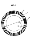
- the rotating sealing ring 3 includes a spiral groove area 38 having a plurality of spiral grooves 31 which are directed from the high pressure fluid side H to the low pressure fluid side L as shown in Fig. 2.
- the rotating sealing ring 3 also has a dam area 32 extending from the spiral groove area 38.
- Fig. 3 is an enlarged cross-sectional view showing the rotating sealing ring 3 and the stationary sealing ring 4.
- the rotating sealing ring 3 is provided with a recess in the spiral groove area 38.
- the height of the ridge portion of the spiral groove area 38 is lower than that of the dam area 32 by the recess h t . That is, there is provided a gap between the ridge portion of the spiral groove area 38 of the rotating sealing ring 3 and the surface of the stationary sealing ring 4 when the machine is stopped.
- Reference numerals 42, 44, 46 and 48 are sealing members such as O ring in Fig. 1. With the above structure, the face seal prevents fluid having high pressure at the high pressure fluid side H from leaking out towards the low pressure fluid side L to the utmost extent.
- Relative motion of the rotating sealing ring 3 and the stationary sealing ring 4 is caused by rotating the rotating shaft 1.
- the face seal will be exposed to hydrostatic forces from fluid pressure and hydrodynamic forces from the spiral grooves.
- the spiral groove pattern pumps fluid (gas) inward to thereby form fluid film on the sealing surfaces.
- the rotating sealing ring 3 is brought out of contact with the stationary sealing ring 4, thus forming the gap h between the sealing surfaces of the rotating sealing ring 3 and the stationary sealing ring 4. That is, the dam area 32 of the rotating sealing ring 3 is brought out of contact with the surface 50 of the stationary sealing ring 4.
- the leakage of fluid is restricted by keeping the gap h between two sealing surfaces small.
- the load applied to the solid contact portion of the sealing surfaces is reduced by ⁇ (r 2 2 - rg 2 )P 2 /2.
- the starting resistance is decreased by the quantity corresponding to the reduced load when starting the machine.
- the recess h t In the case where the recess h t is large, pumping action by the spiral grooves is decreased. Therefore, there is a possibility that function of avoiding the solid contact of the sealing surfaces is impaired, it is desirable to make the recess h t small. Taking into consideration unevenness of surface condition of the sealing ring caused by working such as lapping (not more than 1 /1.m), deformation caused by heat or pressure, it is desirable to make the recess h t small under the condition that high pressure fluid can be sufficiently entered into the recess. That is, the recess of not more than 3 ⁇ m is preferably selected.
- the end face seal of the present invention is provided with the recess h t unlike the conventional end face seal for the purpose of reducing the starting resistance.
- the end face seal includes a sealing ring which has a step on the surface extending radially outwardly. That is, the sealing ring has two surfaces, one of which is formed with spiral grooves on the spiral groove area for pumping action to pump fluid of the high pressure side to the low pressure side, the other of which has a flat surface on the dam area for restricting the fluid flow from the high pressure side to the low pressure side and performing sealing action.
- the sealing ring has the spiral groove area for pumping action and the dam area for sealing action.
- the end face seal of the present invention is provided with the recess h t for the purpose of reduction of the starting resistance.
- Figs. 5 through 8 characteristics of the end face seal of the present invention is shown in Figs. 5 through 8 on condition of table 1.
- the spiral groove angle is defined as an angle between velocity vector at a point of the spiral groove and tangent of the point of the spiral groove.
- Fig. 5 shows the effect of reduction of load of the sealing surfaces by forming the recess h t .
- the horizontal axis represents the dam width ratio (DW)
- the vertical axis represents the load ratio (Fi/F 2 ) of the end face seal having the recess h t relative to the end face seal having no recess, wherein the former (F 1 ) is obtained using the formula (2) and the latter (F 2 ) is obtained using the formula (1).
- the gap of the sealing surface (h), the leakage rate (Q) and the film stiffness (dW/dh) having 1 ⁇ m in thickness are shown in Figs. 6 through 8.
- the gap of the sealing surfaces of 1 ⁇ m is chosen because there is a fair chance to occur the solid contact.
- the sealing surfaces having the recess is shown using the solid lines, the sealing surfaces having no recess is shown using broken lines.
- the film stiffness is remarkably decreased by forming the recess h t as shown in Fig. 8.
- the film stiffness is decreased, especially, at the range of shallow groove depth (ho).
- the gap of the sealing surfaces (h) and the leakage rate (Q) are not affected so much by the recess in the range of small dam width ratio of 0.3 or thereabouts.
- the starting resistance can be greatly reduced by forming the recess as shown in Fig. 5, however, the film stiffness is lowered as shown in Fig. 8.
- the decrease of the film stiffness is disadvantageous because there develops a tendency to cause the solid contact and to prevent normal operation. Therefore, the film stiffness must be improved.
- the groove depth (ho) and the dam width ratio (DW) are closely connected with the film stiffness among the above three factors as shown in Fig. 8. To be more specific, when the groove depth ho is becoming smaller, the film stiffness is becoming higher. On the contrary, when the groove depth ho is becoming smaller, the gap of the sealing surfaces is becoming narrower as shown in Fig. 6 and the leakage rate smaller as shown in Fig. 7.
- the lower limit of the groove depth ho is preferably 3 /1.m.
- the upper limit of the groove depth is expanded up to 15 ⁇ m in consideration of rough sealing effect which is applicable to a relatively low pressure fluid.
- the dam width ratio is becoming smaller, the film stiffness is becoming higher as shown in Fig. 8. Therefore, as far as the film stiffness is concerned, it is desirable to make the dam width ratio small.
- the dam width ratio small, the leakage rate increases as shown in Fig. 7.
- the lower limit of the dam width ratio is preferably 0.2.
- the upper limit of the dam width ratio is preferably 0.4 so that the film stiffness does not become excessively small.
- Figs. 9 through 12 Those parts and components in Figs. 9 through 12 which are structurally and functionally identical to those shown in Figs. 1 through 4 are denoted using the same reference numerals.
- Fig. 9 is a cross-sectional view showing a spiral groove face seal according to a second embodiment of the present invention.
- the recess h t is provided on the stationary ring 4.
- the area where the recess h t is formed is the same area as the spiral groove area 38.
- the second embodiment has the same function and effect as the first embodiment in Fig.s 1 through 4.
- Fig. 10 is a cross-sectional view showing a spiral groove face seal according to a third embodiment of the present invention.
- the recess h t extends in the dam area 32.
- the recess h t is formed on the rotating sealing ring 3 in Fig. 10(a), and the recess h t is formed on the stationary sealing ring 4 in Fig. 10(b).
- the load applied to the solid contact portion of the sealing surfaces is expressed by the following formula. where 2r t is inside diameter of the recess h t .
- the load of this embodiment is smaller than that of the first embodiment in Fig.s 1 through 4.
- Fig. 11 is a cross-sectional view showing a spiral groove face seal according to a fourth embodiment of the present invention.
- the recess h t is located inside the spiral groove area 38.
- the recess h t is formed on the rotating sealing ring 3 in Fig. 11 (a), and the recess h t is formed on the stationary sealing ring 4 in Fig. 11 (b).
- the load applied to the solid contact portion of the sealing surfaces is expressed by the following formula. where 2r t is inside diameter of the recess h t .
- the load of this embodiment is larger than that of the first embodiment in Figs. 1 through 4.
- the outside of the spiral groove area is high pressure side and the inside of the spiral groove is low pressure side, the fluid flows inwardly at the sealing surfaces.
- a fifth embodiment in Fig. 12 the outside of the spiral groove area is low pressure side and the inside of the spiral groove area is high pressure side, the fluid flows outwardly at the sealing surfaces.
- the fifth embodiment has the same function and effect as the embodiments in Fig.s 1 through 11.
- the spiral groove face seal of the present invention since fluid can enter into the sealing surfaces through the recess in such a state that the rotating sealing ring is in contact with the stationary sealing ring at at least a part of the sealing surfaces, the starting resistance can be remarkably reduced and the starting torque required to start the machine are reduced under high pressure, thus avoiding a failure in starting the machine and preventing the sealing surfaces from being damaged.
- the recess is provided on one of the sealing rings, so that pumping action generated by the spiral grooves is affected by the recess.
- a desirable performance is obtained by selecting the range of the groove depth (ho), the dam width ratio (DW) and the balance (BR), thereby preventing noncontacting function of the sealing surfaces from being impaired.
- the rotating sealing ring contacts the stationary sealing ring at the dam area, leakage of fluid from the high pressure side to the low pressure side can be prevented when the machine is stopped.
Landscapes
- Engineering & Computer Science (AREA)
- General Engineering & Computer Science (AREA)
- Mechanical Engineering (AREA)
- Mechanical Sealing (AREA)
Abstract
Description
- The present invention relates to a spiral groove face seal, and more particularly to a spiral groove face seal in which an end face of a rotating sealing ring rotatable with a rotating shaft and an end face of a stationary sealing ring facing the rotating sealing ring form sealing surfaces for restricting a fluid flow from a high pressure side to a low pressure side.
- In general, a spiral groove face seal is used for sealing the space between a rotating shaft and housing thereof. The spiral groove face seal is incorporated in, for example, gas turbines or compressors which generate high pressure.
- Conventionally, the end face seal comprises two annular sealing rings facing with each other, one of which includes a spiral groove area having a plurality of spiral grooves and a dam area extending from the spiral groove area and having a flat surface, the other of which has a flat surface.
- The end face seal of this type is disclosed in, for example, U.S. Pat. No. 4,212,475. In U.S. Pat. No. 4,212,475 spiral grooves are formed on a rotating sealing ring as shown in Figs. 13 through 15. In Figs. 13 through 15, a rotating
shaft 1 accommodated in ahousing 9 is provided with asleeve 2. Thesleeve 2 is connected to a rotating sealingring 3 through a pin. Astationary sealing ring 4 is pressed against the rotatingsealing ring 3 by urging force ofsprings 10 interposed between a sealingring retainer 5 and aspring retainer 6. The rotatingsealing ring 3 includes aspiral groove area 35 having a plurality ofspiral grooves 33 and adam area 34 extending from thespiral groove area 35 and having a flat surface. Thespiral grooves 33 serves to pump fluid (gas) inwardly, and thedam area 34 serves to restrict fluid flow pumped by thespiral grooves 33. - Relative motion of the rotating
sealing ring 3 and thestationary sealing ring 4 is caused by rotating the rotatingshaft 1. Under dynamic conditions, the end face seal will be exposed to hydrostatic forces from fluid pressure and hydrodynamic forces from thespiral grooves 33. The spiral groove pattern pumps fluid (gas) inwardly to thereby form fluid film on the sealing surfaces, whereby the rotatingsealing ring 3 is brought out of contact with thestationary sealing ring 4. The leakage of fluid is restricted by keeping the gap between the sealing surfaces small. - On the other hand, another type of end seal face is disclosed in U.S. Pat. No. 3,499,653. In U.S. Pat. No. 3,499,653 the end face seal comprises a rotating sealing ring and a stationary sealing ring as well as the end face seal in Fig. 13 through 15. One of the sealing rings has spiral grooves and a tapered surface to provide the necessary wedge-shaped space at the radially outer regions thereof.
- In the end face seal of this type, when fluid enters into the wedge-shaped space between the rotating sealing ring and the stationary sealing ring, the sealing surfaces become noncontact by hydrostatic forces from fluid pressure. When the fluid has low pressure, the sealing surfaces do not become noncontact only by hydrostatic forces, but become noncontact by hydrodynamic forces from the spiral grooves in addition to hydrostatic forces.
- However, in the end face seal disclosed in U.S. Pat. No. 4,212,475, a ridge portion (on which spiral grooves are not formed) on the
spiral groove area 35 is located on the same plane as thedam area 34 as shown in Figs. 13 through 15. Therefore, when starting the end face seal, the ridge portion and thedam area 34 of the rotatingsealing ring 3 contact directly the surface of thestationary sealing ring 4 facing thereto. In this specification, this direct contact of two solid members is defined as "solid contact." As a result, fluid (gas) cannot be entered into the contacting surfaces of two sealing members, a large quantity of starting torque is thus required due to a large quantity of sliding resistance when starting in such a state that fluid pressure is applied to the sealing rings. The same is true in the stationary sealing ring having spiral grooves. - On the other hand, the end face seal disclosed in U.S. Pat. No. 3,499,653 is a hydrostatic mechanical seal of the gap type so that the sealing surfaces become noncontact by hydrostatic forces from fluid pressure. Therefore, there is no problem in starting resistance at the time of starting. However, since the sealing surfaces become noncontact by hydrostatic force from fluid, fluid is leaked from the sealing surfaces having a certain gap when the machine incorporating the seal face is stopped.
- It is therefore an object of the present invention to provide a spiral groove face seal which can lower starting torque by reducing starting resistance when starting the machine and prevent fluid from leaking from a high pressure side to a low pressure side when the machine is stopped.
- According to the present invention, there is provided a spiral groove face seal having a stationary sealing ring and a rotating sealing ring with opposed radially extending sealing surfaces, the rotating sealing ring being in contact with the stationary sealing ring at at least a part of the sealing surfaces when the rotating sealing ring is stopped, the rotating ring being brought out of contact with the stationary sealing ring when the rotating sealing ring is rotated, the improvement comprising: spiral grooves formed in one of the sealing surfaces and extending from one circumference of the sealing surface in a radial direction and from a high pressure fluid side to a low pressure fluid side so as to pump fluid in the high pressure fluid side towards the low pressure fluid side; and a recess formed in one of the sealing surfaces, the recess being located in an area of the spiral grooves or a part of the spiral grooves.
- With the above structure, fluid can enter into the sealing surfaces through the recess in such a state that the rotating sealing ring is in contact with the stationary sealing ring at at least a part of the sealing surfaces, the starting resistance can be remarkably reduced and the starting torque required to start the machine is reduced under high pressure, thus meeting the needs of saving energy. In the case where the depth of the recess is large, there is a possibility that pumping action generated by the spiral grooves is affected by the recess to thereby impair the noncontacting function. However, adverse influences on pumping action is not caused because the depth of the recess is not large. The depth of recess is preferably not more than 3 /1.m in consideration of surface roughness caused by working and unevenness of surface. Further, according to the present invention, since the rotating sealing ring contacts the stationary sealing ring at a part of sealing surfaces (the dam area), leakage of fluid from the high pressure side to the low pressure side can be prevented when the machine is stopped.
- The above and other objects, features and advantages of the present invention will become more apparent from the following description when taken in conjunction with the accompanying drawings in which preferred embodiments of the present invention are shown by way of illustrative example.
- In the drawings:
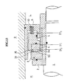
- Fig. 1 is a cross-sectional view showing a spiral groove face seal according to an embodiment of the present invention;
- Fig. 2 is an end view showing spiral grooves formed on a rotating sealing ring of the spiral groove face seal according to the embodiment of the present invention;
- Fig. 3 is an enlarged cross-sectional view showing the rotating sealing ring and a stationary sealing ring of the spiral groove face seal according to the embodiment of the present invention;
- Fig. 4 is a cross-sectional view showing an operation of the spiral groove face seal according to the embodiment of the present invention;
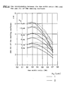
- Fig. 5 is a graph showing the relationship of the dam width ratio (DW) and the load ratio (Fi/F2) of the end face seal having the recess ht relative to the end face seal having no recess;
- Fig. 6 is a graph showing the relationship between the dam width ratio (DW) and the gap (h) of the sealing surfaces of the end face seal;
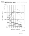
- Fig. 7 is a graph showing the relationship between the dam width ratio (DW) and the leakage rate (Q) of the end face seal;
- Fig. 8 is a graph showing the relationship between the dam width ratio (DW) and the film stiffness (dW/dh);
- Fig. 9 is a cross-sectional view showing a spiral groove face seal according to a second embodiment of the present invention;
- Fig. 10 is a cross-sectional view showing a spiral groove face seal according to a third embodiment of the present invention;
- Fig. 11 is a cross-sectional view showing a spiral groove face seal according to a fourth embodiment of the present invention;
- Fig. 12 is a cross-sectional view showing a spiral groove face seal according to a fifth embodiment of the present
invention; Fig. 13 is a cross-sectional view showing a conventional spiral groove face seal; - Fig. 14 is a cross-sectional view showing a rotating sealing ring of the conventional spiral groove face seal; and
- Fig. 15 is an end view showing spiral grooves of the conventional spiral groove face seal.
- A spiral groove face seal of the present invention will be described below with reference to Figs. 1 through 8.
- In Fig. 1, a
sleeve 2 is fixedly secured to arotating shaft 1 accommodated in ahousing 9. Arotating sealing ring 3 is connected to thesleeve 2 through apin 20. Therotating sealing ring 3 faces astationary ring 4, and when starting, therotating sealing ring 3 contacts thestationary ring 4 at thedam area 32 in a state of solid contact. Therotating sealing ring 3 comprises an annular body defining annular surfaces on the opposite sides thereof. Incidentally, therotating sealing ring 3 is fixedly secured to thesleeve 2 by asleeve 7 and a retainingnut 8. - A
stationary sealing ring 4 is pressed against therotating sealing ring 3 by urging force ofcoiled springs 10 interposed between a sealingring retainer 5 and aspring retainer 6. Therotating sealing ring 3 includes aspiral groove area 38 having a plurality ofspiral grooves 31 which are directed from the high pressure fluid side H to the low pressure fluid side L as shown in Fig. 2. Therotating sealing ring 3 also has adam area 32 extending from thespiral groove area 38. - Fig. 3 is an enlarged cross-sectional view showing the
rotating sealing ring 3 and thestationary sealing ring 4. Therotating sealing ring 3 is provided with a recess in thespiral groove area 38. The height of the ridge portion of thespiral groove area 38 is lower than that of thedam area 32 by the recess ht. That is, there is provided a gap between the ridge portion of thespiral groove area 38 of therotating sealing ring 3 and the surface of thestationary sealing ring 4 when the machine is stopped.Reference numerals - Next, the operation of the spiral groove face seal thus constructed will be described below with reference to Fig. 4.
- Relative motion of the
rotating sealing ring 3 and thestationary sealing ring 4 is caused by rotating therotating shaft 1. Under dynamic conditions, the face seal will be exposed to hydrostatic forces from fluid pressure and hydrodynamic forces from the spiral grooves. The spiral groove pattern pumps fluid (gas) inward to thereby form fluid film on the sealing surfaces. As a result, therotating sealing ring 3 is brought out of contact with thestationary sealing ring 4, thus forming the gap h between the sealing surfaces of therotating sealing ring 3 and thestationary sealing ring 4. That is, thedam area 32 of therotating sealing ring 3 is brought out of contact with thesurface 50 of thestationary sealing ring 4. The leakage of fluid is restricted by keeping the gap h between two sealing surfaces small. - In the conventional end face seal, since reduction of starting torque is not considered, the recess is not provided (ht = 0 /1.m). Fluid pressure at the high pressure side H is represented by P2, fluid pressure at the low pressure side L is represented by Pi. Assuming that fluid is not entered into the sealing surfaces of the solid contact (contacting portion of the
surface 32 and thesurface 50 at the dam area) from the surroundings. The width of the spiral groove is equal to the width of the ridge. In other words, the area of the ridge portion is equal to that of the spiral grooves. - In the conventional end face seal in Figs. 13 through 15, the load applied to the solid contact portion of the sealing surfaces is expressed by the following formula.

where F sp is urging force generated by the coiled springs 10. - On the other hand, in the end face seal of the present invention in Figs. 1 and 2, the load applied to the solid contact portion of the sealing surfaces is expressed by the following formula.

- According to the present invention, the load applied to the solid contact portion of the sealing surfaces is reduced by π(r2 2 - rg2)P2/2. The starting resistance is decreased by the quantity corresponding to the reduced load when starting the machine.
- In the case where the recess ht is large, pumping action by the spiral grooves is decreased. Therefore, there is a possibility that function of avoiding the solid contact of the sealing surfaces is impaired, it is desirable to make the recess ht small. Taking into consideration unevenness of surface condition of the sealing ring caused by working such as lapping (not more than 1 /1.m), deformation caused by heat or pressure, it is desirable to make the recess ht small under the condition that high pressure fluid can be sufficiently entered into the recess. That is, the recess of not more than 3 µm is preferably selected.
- The end face seal of the present invention is provided with the recess ht unlike the conventional end face seal for the purpose of reducing the starting resistance. The end face seal includes a sealing ring which has a step on the surface extending radially outwardly. That is, the sealing ring has two surfaces, one of which is formed with spiral grooves on the spiral groove area for pumping action to pump fluid of the high pressure side to the low pressure side, the other of which has a flat surface on the dam area for restricting the fluid flow from the high pressure side to the low pressure side and performing sealing action. In other words, the sealing ring has the spiral groove area for pumping action and the dam area for sealing action.
- As mentioned above, the end face seal of the present invention is provided with the recess ht for the purpose of reduction of the starting resistance. As a result, the gap and film stiffness are lowered compared with the conventional spiral groove face seal. Therefore, the groove depth (ho), the balance (BR = (r2 2 - rb 2)/(r2 2 - r1 2)) and the dam width ratio (DW = (rg - ri)/(r2 - ri)) must be properly chosen to maintain a narrow gap between two surfaces of the sealing rings without causing the solid contact by various disturbance such as vibration in an axial direction of the sealing surfaces, vibration in an inclined direction relative to the axis, or deformation.
- Next, characteristics of the end face seal of the present invention is shown in Figs. 5 through 8 on condition of table 1.

where the spiral groove angle is defined as an angle between velocity vector at a point of the spiral groove and tangent of the point of the spiral groove. - Fig. 5 shows the effect of reduction of load of the sealing surfaces by forming the recess ht. In Fig. 5, the horizontal axis represents the dam width ratio (DW), the vertical axis represents the load ratio (Fi/F2) of the end face seal having the recess ht relative to the end face seal having no recess, wherein the former (F1) is obtained using the formula (2) and the latter (F2) is obtained using the formula (1).
- As is apparent from Fig. 5, the smaller the dam width ratio is becoming, the smaller the load ratio is becoming. Assuming that coefficients of friction at all points on the sealing surfaces are the same, the starting resistance can be greatly reduced by forming the recess ht.
- Further, when the balance is constant (BR = 0.897), and the dam width ratio (DW) and the groove depth (ho) are variable, the gap of the sealing surface (h), the leakage rate (Q) and the film stiffness (dW/dh) having 1 µm in thickness are shown in Figs. 6 through 8. When calculating the film stiffness (dW/dh), the gap of the sealing surfaces of 1 µm is chosen because there is a fair chance to occur the solid contact.
- In Figs. 6 through 8, the sealing surfaces having the recess is shown using the solid lines, the sealing surfaces having no recess is shown using broken lines. The film stiffness is remarkably decreased by forming the recess ht as shown in Fig. 8. The film stiffness is decreased, especially, at the range of shallow groove depth (ho). On the other hand, the gap of the sealing surfaces (h) and the leakage rate (Q) are not affected so much by the recess in the range of small dam width ratio of 0.3 or thereabouts.
- Next, in the end face seal of the present invention, a process of determining preferable range of the groove depth (ho), the dam width ratio (DW) and the balance (BR) will be described below on the basis of the result of Fiqs. 5
throuqh 8. - In the end face seal of the present invention, the starting resistance can be greatly reduced by forming the recess as shown in Fig. 5, however, the film stiffness is lowered as shown in Fig. 8. The decrease of the film stiffness is disadvantageous because there develops a tendency to cause the solid contact and to prevent normal operation. Therefore, the film stiffness must be improved. The groove depth (ho) and the dam width ratio (DW) are closely connected with the film stiffness among the above three factors as shown in Fig. 8. To be more specific, when the groove depth ho is becoming smaller, the film stiffness is becoming higher. On the contrary, when the groove depth ho is becoming smaller, the gap of the sealing surfaces is becoming narrower as shown in Fig. 6 and the leakage rate smaller as shown in Fig. 7. However, in the case where the gap of the sealing surfaces is too small, there is a possibility to occur the solid contact of the sealing surfaces. Therefore, an extremely small groove depth ho cannot be chosen. Further, taking into consideration working error of the groove, the groove depth ho of an extremely small value cannot be chosen from this aspect too. Accordingly, in the end face seal of the present invention, the lower limit of the groove depth ho is preferably 3 /1.m. On the contrary, the upper limit of the groove depth is expanded up to 15 µm in consideration of rough sealing effect which is applicable to a relatively low pressure fluid.
- Next, the relationship between the dam width ratio and the film stiffness will be explained below. When the dam width ratio is becoming smaller, the film stiffness is becoming higher as shown in Fig. 8. Therefore, as far as the film stiffness is concerned, it is desirable to make the dam width ratio small. On the other hand, when making the dam width ratio small, the leakage rate increases as shown in Fig. 7. Further, in the case where the dam width ratio is extremely small and there are flaws or chips on the sealing ring at the
dam area 32, the end face seal does not function as seal due to leakage of fluid therefrom. Accordingly, in the end face seal of the present invention, the lower limit of the dam width ratio is preferably 0.2. The upper limit of the dam width ratio is preferably 0.4 so that the film stiffness does not become excessively small. - Concerning the balance, taking into consideration the fact that the solid contact is kept at the dam area of the sealing surfaces when the machine is stopped and leakage of fluid is minimized from the high pressure side to the low pressure side, it is desirable to select the balance of between 0.8 and 0.9.
- As is apparent from the foregoing description, the preferable range of the groove depth (ho), the dam width ratio (DW = (rg - ri)/(r2 - ri)) and the balance (BR = (r2 2 - rb2)/(r22 - r,2)) are shown in table 2.

- Next, other embodiments of the present invention will be described below with reference to Figs. 9 through 12. Those parts and components in Figs. 9 through 12 which are structurally and functionally identical to those shown in Figs. 1 through 4 are denoted using the same reference numerals.
- Fig. 9 is a cross-sectional view showing a spiral groove face seal according to a second embodiment of the present invention. According to this embodiment, the recess ht is provided on the
stationary ring 4. The area where the recess ht is formed is the same area as thespiral groove area 38. The second embodiment has the same function and effect as the first embodiment in Fig.s 1 through 4. - Fig. 10 is a cross-sectional view showing a spiral groove face seal according to a third embodiment of the present invention. According to this embodiment, the recess ht extends in the
dam area 32. The recess ht is formed on therotating sealing ring 3 in Fig. 10(a), and the recess ht is formed on thestationary sealing ring 4 in Fig. 10(b). - The load applied to the solid contact portion of the sealing surfaces is expressed by the following formula.

where 2rt is inside diameter of the recess ht. - Therefore, the load of this embodiment is smaller than that of the first embodiment in Fig.s 1 through 4.
- Fig. 11 is a cross-sectional view showing a spiral groove face seal according to a fourth embodiment of the present invention. According to this embodiment, the recess ht is located inside the
spiral groove area 38. The recess ht is formed on therotating sealing ring 3 in Fig. 11 (a), and the recess ht is formed on thestationary sealing ring 4 in Fig. 11 (b). - The load applied to the solid contact portion of the sealing surfaces is expressed by the following formula.

where 2rt is inside diameter of the recess ht. - Therefore, the load of this embodiment is larger than that of the first embodiment in Figs. 1 through 4.
- In the embodiments in Figs. 1 through 11, the outside of the spiral groove area is high pressure side and the inside of the spiral groove is low pressure side, the fluid flows inwardly at the sealing surfaces. On the contrary, in a fifth embodiment in Fig. 12, the outside of the spiral groove area is low pressure side and the inside of the spiral groove area is high pressure side, the fluid flows outwardly at the sealing surfaces. The fifth embodiment has the same function and effect as the embodiments in Fig.s 1 through 11.
- As is apparent from the foregoing description, according to the spiral groove face seal of the present invention, since fluid can enter into the sealing surfaces through the recess in such a state that the rotating sealing ring is in contact with the stationary sealing ring at at least a part of the sealing surfaces, the starting resistance can be remarkably reduced and the starting torque required to start the machine are reduced under high pressure, thus avoiding a failure in starting the machine and preventing the sealing surfaces from being damaged.
- Further, according to the present invention, the recess is provided on one of the sealing rings, so that pumping action generated by the spiral grooves is affected by the recess. However, a desirable performance is obtained by selecting the range of the groove depth (ho), the dam width ratio (DW) and the balance (BR), thereby preventing noncontacting function of the sealing surfaces from being impaired. Furthermore, according to the present invention, since the rotating sealing ring contacts the stationary sealing ring at the dam area, leakage of fluid from the high pressure side to the low pressure side can be prevented when the machine is stopped.
- Although certain preferred embodiments have been shown and described, it should be understood that many changes and modifications may be made therein without departing from the scope of the appended claims.
Claims (9)


where groove diameter 2rg is the diameter of a circle defined by the boundary of the grooved area and the ungrooved area in said sealing surface, 2r, is the inside diameter and 2r2 is the outside diameter; and


where 2r2 is the outside diameter of the sealing interface, 2r, is the inside diameter and 2rb is the balance diameter.
Applications Claiming Priority (4)
| Application Number | Priority Date | Filing Date | Title |
|---|---|---|---|
| JP72261/90 | 1990-07-09 | ||
| JP7226190 | 1990-07-09 | ||
| JP3177524A JPH0756345B2 (en) | 1990-07-09 | 1991-06-21 | Non-contact end face seal |
| JP177524/91 | 1991-06-21 |
Publications (3)
| Publication Number | Publication Date |
|---|---|
| EP0466076A2 true EP0466076A2 (en) | 1992-01-15 |
| EP0466076A3 EP0466076A3 (en) | 1992-05-27 |
| EP0466076B1 EP0466076B1 (en) | 1995-10-04 |
Family
ID=26413402
Family Applications (1)
| Application Number | Title | Priority Date | Filing Date |
|---|---|---|---|
| EP91111347A Expired - Lifetime EP0466076B1 (en) | 1990-07-09 | 1991-07-08 | Spiral groove face seal |
Country Status (4)
| Country | Link |
|---|---|
| US (1) | US5180173A (en) |
| EP (1) | EP0466076B1 (en) |
| JP (1) | JPH0756345B2 (en) |
| DE (1) | DE69113539T2 (en) |
Cited By (9)
| Publication number | Priority date | Publication date | Assignee | Title |
|---|---|---|---|---|
| EP0578377A1 (en) * | 1992-07-04 | 1994-01-12 | John Crane Uk Limited | Seals |
| EP0935086A3 (en) * | 1998-02-06 | 2000-04-05 | John Crane Inc. | Gas lubricated slow speed seal |
| EP1079156A1 (en) * | 1999-08-16 | 2001-02-28 | Nippon Pillar Packing Co., Ltd. | Non-contact type mechanical seal |
| WO2002093046A1 (en) * | 2001-05-15 | 2002-11-21 | Aes Engineering Limited | Mechanical seal |
| CN103016743A (en) * | 2012-12-13 | 2013-04-03 | 江苏大学 | Mechanical seal capable of implementing zero wear, zero leakage and preventing solid particles |
| CN104334939A (en) * | 2012-08-04 | 2015-02-04 | 伊格尔工业股份有限公司 | Sliding component |
| CN108131449A (en) * | 2018-01-31 | 2018-06-08 | 大连威尔博合金科技有限公司 | A superhard material surfacing welding mechanical seal ring |
| CN118060499A (en) * | 2024-04-18 | 2024-05-24 | 永红保定铸造机械有限公司 | Hydraulic locking equipment |
| EP4306826A4 (en) * | 2021-03-12 | 2025-03-26 | Eagle Industry Co., Ltd. | SLIDING ELEMENT |
Families Citing this family (76)
| Publication number | Priority date | Publication date | Assignee | Title |
|---|---|---|---|---|
| US5722665A (en) * | 1992-02-26 | 1998-03-03 | Durametallic Corporation | Spiral groove face seal |
| AU685502B2 (en) * | 1993-09-01 | 1998-01-22 | Durametallic Corporation | Face seal with angled and annular grooves |
| WO1995029353A1 (en) * | 1994-04-20 | 1995-11-02 | Durametallic Corporation | Face seal with angled grooves |
| US6145840A (en) * | 1995-06-02 | 2000-11-14 | Stein Seal Company | Radial flow seals for rotating shafts which deliberately induce turbulent flow along the seal gap |
| JP3781463B2 (en) * | 1995-11-10 | 2006-05-31 | 株式会社ニクニ | mechanical seal |
| US5934683A (en) * | 1997-07-10 | 1999-08-10 | Roy E. Roth Company | Rotary seal assembly having grooved seal facing |
| US6109617A (en) * | 1998-03-04 | 2000-08-29 | Power Packing Co., Inc. | Gas seal assembly and method of sealing |
| JP3650954B2 (en) | 1998-09-18 | 2005-05-25 | イーグル工業株式会社 | Non-contact mechanical seal for high speed |
| US6189896B1 (en) | 1999-04-08 | 2001-02-20 | Caterpillar Inc. | Controlled leakage rotating seal ring with elements for receiving and holding a lubricant on a face thereof |
| US6341782B1 (en) * | 2000-03-03 | 2002-01-29 | Surface Technologies Ltd | Lubricated seals having micropores |
| US6454268B1 (en) * | 2001-02-09 | 2002-09-24 | Eagle Industry Co., Ltd. | Shaft seal device |
| GB0202468D0 (en) * | 2002-02-02 | 2002-03-20 | Crane John Uk Ltd | Seals |
| US20060207834A1 (en) * | 2005-03-03 | 2006-09-21 | Honeywell International, Inc. | Aircraft engine accessory drive air film riding bulkhead seal |
| US8105021B2 (en) * | 2007-08-20 | 2012-01-31 | United Technologies Corp. | Gas turbine engine systems involving hydrostatic face seals with integrated back-up seals |
| US8109717B2 (en) * | 2007-08-17 | 2012-02-07 | United Technologies Corp. | Gas turbine engine systems involving hydrostatic face seals with integrated back-up seals |
| US8109716B2 (en) * | 2007-08-17 | 2012-02-07 | United Technologies Corp. | Gas turbine engine systems involving hydrostatic face seals with anti-fouling provisioning |
| US20090051120A1 (en) * | 2007-08-23 | 2009-02-26 | United Technologies Corp. | Gas Turbine Engine Systems Involving Hydrostatic Face Seals |
| US7797941B2 (en) * | 2007-10-26 | 2010-09-21 | United Technologies Corporation | Gas turbine engine systems involving hydrostatic face seals |
| US8167545B2 (en) * | 2008-02-27 | 2012-05-01 | United Technologies Corp. | Self-balancing face seals and gas turbine engine systems involving such seals |
| US9039013B2 (en) * | 2011-05-04 | 2015-05-26 | United Technologies Corporation | Hydrodynamic non-contacting seal |
| US9062775B2 (en) * | 2011-07-01 | 2015-06-23 | Eaton Corporation | Scooping hydrodynamic seal |
| US9958010B2 (en) | 2012-08-04 | 2018-05-01 | Eagle Industry Co., Ltd. | Sliding component |
| US9482158B2 (en) | 2012-09-21 | 2016-11-01 | United Technologies Corporation | Turbomachine hybrid lift-off face seal |
| CN102927287A (en) * | 2012-11-12 | 2013-02-13 | 南京林业大学 | Mechanical end face seal with combined fluid slot structure |
| US8926184B2 (en) * | 2012-11-22 | 2015-01-06 | Seagate Technology Llc | Fluid bearing with non-uniform grooves |
| WO2014116800A1 (en) * | 2013-01-23 | 2014-07-31 | Flowserve Management Company | Mechanical face seal with a reverse trapezoidal face pattern |
| US9091130B2 (en) * | 2013-02-13 | 2015-07-28 | Varel International, Ind., L.P. | Rock bit having a radially self-aligning metal faced seal |
| JP5944852B2 (en) * | 2013-03-15 | 2016-07-05 | イーグルブルグマンジャパン株式会社 | Sealing structure |
| WO2014184603A1 (en) | 2013-05-16 | 2014-11-20 | Dresser-Rand Sa | Bi-directional shaft seal |
| WO2015031474A1 (en) | 2013-08-27 | 2015-03-05 | Eaton Corporation | Seal ring composite for improved hydrodynamic seal performance |
| US9714712B2 (en) | 2014-08-15 | 2017-07-25 | Eaton Corporation | Hydrodynamic mating ring with integrated groove inlet pressure control |
| JP6773649B2 (en) | 2014-10-06 | 2020-10-21 | ジョン クレーン インコーポレーテッド | Mechanical seal with hydropad surface profile |
| JP2016161099A (en) * | 2015-03-04 | 2016-09-05 | 三菱化学株式会社 | Method for transferring liquid containing easily polymerizable compound |
| JP6311644B2 (en) * | 2015-04-28 | 2018-04-18 | 株式会社Soken | Gear pump device |
| EP3109470B1 (en) | 2015-06-26 | 2019-03-27 | Danfoss A/S | Hydraulic machine arrangement |
| ES2866629T3 (en) | 2015-06-26 | 2021-10-19 | Danfoss As | Pallet Cell Machine |
| EP3109468B1 (en) * | 2015-06-26 | 2022-06-29 | Danfoss A/S | Hydraulic machine |
| JP6903747B2 (en) | 2016-06-10 | 2021-07-14 | ジョン クレーン ユーケイ リミテッド | Dry gas seal with electronically controlled shutoff valve |
| US10415707B2 (en) | 2016-06-30 | 2019-09-17 | General Electric Company | Face seal assembly and an associated method thereof |
| US10626743B2 (en) | 2016-06-30 | 2020-04-21 | General Electric Company | Segmented face seal assembly and an associated method thereof |
| EP3499098B1 (en) | 2016-08-15 | 2024-04-24 | Eagle Industry Co., Ltd. | Sliding component |
| USRE50849E1 (en) | 2016-11-16 | 2026-03-31 | Eagle Industry Co., Ltd. | Sliding component |
| US11125334B2 (en) | 2016-12-21 | 2021-09-21 | Eaton Intelligent Power Limited | Hydrodynamic sealing component and assembly |
| US11187326B2 (en) * | 2017-05-12 | 2021-11-30 | Eagle Industry Co., Ltd. | Mechanical seal |
| WO2018213313A1 (en) | 2017-05-15 | 2018-11-22 | John Crane Uk Ltd. | Dry gas seal with electronically controlled carrier load |
| EP3739242A4 (en) | 2018-01-12 | 2021-10-13 | Eagle Industry Co., Ltd. | SLIDING ELEMENT |
| JP7139077B2 (en) | 2018-02-01 | 2022-09-20 | イーグル工業株式会社 | sliding parts |
| CN108506350A (en) * | 2018-03-27 | 2018-09-07 | 北京化工大学 | A kind of sealed bearing assembly and bearing housing |
| CN108825788A (en) * | 2018-07-19 | 2018-11-16 | 天津科技大学 | Mechanical sealing end face structure |
| EP3922874A4 (en) | 2019-02-04 | 2022-11-09 | Eagle Industry Co., Ltd. | SLIDING ELEMENT |
| WO2020162350A1 (en) | 2019-02-04 | 2020-08-13 | イーグル工業株式会社 | Sliding component |
| CN113348308B (en) | 2019-02-04 | 2023-05-05 | 伊格尔工业股份有限公司 | Sliding member |
| EP4253779B1 (en) | 2019-02-04 | 2024-12-18 | Eagle Industry Co., Ltd. | Sliding component and method for manufacturing sliding component |
| WO2020162351A1 (en) | 2019-02-04 | 2020-08-13 | イーグル工業株式会社 | Sliding component |
| KR102647265B1 (en) | 2019-02-04 | 2024-03-14 | 이구루코교 가부시기가이샤 | sliding parts |
| WO2020166589A1 (en) * | 2019-02-14 | 2020-08-20 | イーグル工業株式会社 | Sliding components |
| US11821461B2 (en) | 2019-02-15 | 2023-11-21 | Eagle Industry Co., Ltd. | Sliding components |
| JP7374573B2 (en) * | 2019-02-21 | 2023-11-07 | イーグル工業株式会社 | sliding parts |
| JP7419346B2 (en) | 2019-03-22 | 2024-01-22 | イーグル工業株式会社 | sliding parts |
| US10961816B1 (en) | 2020-01-20 | 2021-03-30 | Absolute Control, LLC | Oilwell choke |
| CN115298462B (en) | 2020-03-31 | 2025-04-11 | 伊格尔工业股份有限公司 | Sliding member |
| KR102798715B1 (en) | 2020-05-11 | 2025-04-23 | 이구루코교 가부시기가이샤 | Sliding parts |
| WO2022009766A1 (en) | 2020-07-06 | 2022-01-13 | イーグル工業株式会社 | Sliding component |
| KR20230022986A (en) | 2020-07-06 | 2023-02-16 | 이구루코교 가부시기가이샤 | sliding parts |
| WO2022009770A1 (en) | 2020-07-06 | 2022-01-13 | イーグル工業株式会社 | Sliding component |
| WO2022009771A1 (en) | 2020-07-06 | 2022-01-13 | イーグル工業株式会社 | Sliding component |
| KR20230027187A (en) | 2020-07-06 | 2023-02-27 | 이구루코교 가부시기가이샤 | sliding parts |
| EP4177485A4 (en) | 2020-07-06 | 2024-07-24 | Eagle Industry Co., Ltd. | SLIDING COMPONENT |
| JP7809645B2 (en) | 2020-09-29 | 2026-02-02 | イーグル工業株式会社 | Sliding parts |
| CN116348693A (en) | 2020-10-14 | 2023-06-27 | 伊格尔工业股份有限公司 | sliding parts |
| EP4394213A4 (en) | 2021-08-25 | 2025-08-27 | Eagle Ind Co Ltd | PAIR OF SLIDING COMPONENTS |
| CN115325034B (en) * | 2022-08-16 | 2023-08-08 | 南京林业大学 | A high-speed rolling bearing sealing structure with fluid self-pumping effect |
| US12529429B2 (en) | 2023-08-28 | 2026-01-20 | Bestway Oilfield, Inc. | Dynamic slab gate valves |
| US12560244B2 (en) | 2023-08-28 | 2026-02-24 | Bestway Oilfield, Inc. | Dynamic slab gate valves |
| US12584560B2 (en) | 2023-08-28 | 2026-03-24 | Bestway Oilfield, Inc. | Gate valves with dynamic skirts and multiple energizers |
| US12565933B1 (en) | 2024-08-30 | 2026-03-03 | Bestway Oilfield, Inc. | Concentric valve skirts |
Family Cites Families (17)
| Publication number | Priority date | Publication date | Assignee | Title |
|---|---|---|---|---|
| GB944360A (en) * | 1954-03-06 | 1963-12-11 | Atomic Energy Authority Uk | Improvements in or relating to gland assemblies |
| US3499653A (en) * | 1968-06-05 | 1970-03-10 | Crane Packing Co | Rotary mechanical seal of the gap type |
| US3751045A (en) * | 1970-03-19 | 1973-08-07 | Ingersoll Rand Co | Fluid seal |
| US3782737A (en) * | 1970-07-13 | 1974-01-01 | Nasa | Spiral groove seal |
| US3675935A (en) * | 1970-07-13 | 1972-07-11 | Nasa | Spiral groove seal |
| DE2222082A1 (en) * | 1972-05-05 | 1973-11-15 | Klein Schanzlin & Becker Ag | NON-CONTACT SHAFT SEAL |
| US4099729A (en) * | 1975-06-18 | 1978-07-11 | Danfoss A/S | Stuffing box backstop ring |
| US4212475A (en) * | 1979-01-15 | 1980-07-15 | Crane Packing Co. | Self aligning spiral groove face seal |
| SU723277A2 (en) * | 1978-03-24 | 1980-03-25 | Peredrij Nikolaj V | Controllable-leakage end seal |
| SU1032856A1 (en) * | 1981-06-18 | 1987-01-23 | Предприятие П/Я М-5356 | End face gland seal |
| IL65289A0 (en) * | 1982-03-19 | 1982-05-31 | Lipschitz Abraham | Hydrodynamic non-contacting seal for rotary machines |
| JPS59231269A (en) * | 1983-06-14 | 1984-12-25 | Arai Pump Mfg Co Ltd | Mechanical seal |
| SU1483150A1 (en) * | 1987-10-28 | 1989-05-30 | Предприятие П/Я В-8772 | Face seal for rotating shaft |
| DE8812629U1 (en) * | 1988-10-07 | 1990-02-08 | Feodor Burgmann Dichtungswerke Gmbh & Co, 8190 Wolfratshausen | poetry |
| US4972986A (en) * | 1988-11-01 | 1990-11-27 | Eg&G Sealol, Inc. | Circumferential inter-seal for sealing between relatively rotatable concentric shafts |
| US5039113A (en) * | 1990-01-17 | 1991-08-13 | Eg&G Sealol, Inc. | Spiral groove gas lubricated seal |
| US5071141A (en) * | 1990-07-17 | 1991-12-10 | John Crane Inc. | Spiral groove seal arrangement for high vapor-pressure liquids |
-
1991
- 1991-06-21 JP JP3177524A patent/JPH0756345B2/en not_active Expired - Lifetime
- 1991-07-08 EP EP91111347A patent/EP0466076B1/en not_active Expired - Lifetime
- 1991-07-08 DE DE69113539T patent/DE69113539T2/en not_active Expired - Fee Related
- 1991-07-09 US US07/727,272 patent/US5180173A/en not_active Expired - Fee Related
Cited By (13)
| Publication number | Priority date | Publication date | Assignee | Title |
|---|---|---|---|---|
| US5496047A (en) * | 1992-07-04 | 1996-03-05 | John Crane Uk Limited | Mechanical seal containing a sealing face with grooved regions which generate hydrodynamic lift between the sealing faces |
| EP0578377A1 (en) * | 1992-07-04 | 1994-01-12 | John Crane Uk Limited | Seals |
| EP0935086A3 (en) * | 1998-02-06 | 2000-04-05 | John Crane Inc. | Gas lubricated slow speed seal |
| US6142478A (en) * | 1998-02-06 | 2000-11-07 | John Crane Inc. | Gas lubricated slow speed seal |
| EP1079156A1 (en) * | 1999-08-16 | 2001-02-28 | Nippon Pillar Packing Co., Ltd. | Non-contact type mechanical seal |
| WO2002093046A1 (en) * | 2001-05-15 | 2002-11-21 | Aes Engineering Limited | Mechanical seal |
| CN104334939A (en) * | 2012-08-04 | 2015-02-04 | 伊格尔工业股份有限公司 | Sliding component |
| CN103016743A (en) * | 2012-12-13 | 2013-04-03 | 江苏大学 | Mechanical seal capable of implementing zero wear, zero leakage and preventing solid particles |
| CN103016743B (en) * | 2012-12-13 | 2015-07-08 | 江苏大学 | Mechanical seal capable of implementing zero wear, zero leakage and preventing solid particles |
| CN108131449A (en) * | 2018-01-31 | 2018-06-08 | 大连威尔博合金科技有限公司 | A superhard material surfacing welding mechanical seal ring |
| CN108131449B (en) * | 2018-01-31 | 2023-08-29 | 大连威尔博合金科技有限公司 | A superhard material surfacing welding mechanical seal ring |
| EP4306826A4 (en) * | 2021-03-12 | 2025-03-26 | Eagle Industry Co., Ltd. | SLIDING ELEMENT |
| CN118060499A (en) * | 2024-04-18 | 2024-05-24 | 永红保定铸造机械有限公司 | Hydraulic locking equipment |
Also Published As
| Publication number | Publication date |
|---|---|
| EP0466076B1 (en) | 1995-10-04 |
| DE69113539D1 (en) | 1995-11-09 |
| JPH0617941A (en) | 1994-01-25 |
| EP0466076A3 (en) | 1992-05-27 |
| DE69113539T2 (en) | 1996-05-30 |
| JPH0756345B2 (en) | 1995-06-14 |
| US5180173A (en) | 1993-01-19 |
Similar Documents
| Publication | Publication Date | Title |
|---|---|---|
| EP0466076B1 (en) | Spiral groove face seal | |
| EP0470409B1 (en) | Noncontacting face seal | |
| JP3885972B2 (en) | Surface sealing device having an annular groove with an angle | |
| US5516118A (en) | Circumferential hydrodynamic seals for sealing a bidirectionally rotatable member | |
| US3973781A (en) | Self-lubricating seal | |
| US6341782B1 (en) | Lubricated seals having micropores | |
| US7377518B2 (en) | Mechanical seal ring assembly with hydrodynamic pumping mechanism | |
| EP0674755B1 (en) | Non-contacting face seal | |
| US7048444B2 (en) | Fluid lubricated bearing device | |
| US7566174B2 (en) | Fluid lubricated bearing device | |
| US3515395A (en) | Unidirectional pumping seal | |
| US7604410B2 (en) | Fluid lubricated bearing device | |
| JPH11508671A (en) | Fluid rotary shaft seals resistant to distortion and torsion | |
| JPS6217467A (en) | Shaft sealing packing | |
| US6056293A (en) | Sealing assembly for a rotary shaft, in particular of an automotive engine water pump | |
| US3494674A (en) | Hydrodynamic bearing for axial and radial loads | |
| US3841720A (en) | Thrust bearing assembly | |
| JPS6231721A (en) | Thrust bearing and seal assembly | |
| US5127660A (en) | Support mechanism for fluid film seals | |
| JPH0143847B2 (en) | ||
| JP2510397Y2 (en) | Seal device | |
| KR102788709B1 (en) | Dynamic pressure shaft sealing device for fluid machine | |
| GB2315824A (en) | Dynamic wear ring | |
| JPS585135Y2 (en) | fluid sliding bearing | |
| JPS6229647B2 (en) |
Legal Events
| Date | Code | Title | Description |
|---|---|---|---|
| PUAI | Public reference made under article 153(3) epc to a published international application that has entered the european phase |
Free format text: ORIGINAL CODE: 0009012 |
|
| AK | Designated contracting states |
Kind code of ref document: A2 Designated state(s): DE GB |
|
| PUAL | Search report despatched |
Free format text: ORIGINAL CODE: 0009013 |
|
| AK | Designated contracting states |
Kind code of ref document: A3 Designated state(s): DE GB |
|
| 17P | Request for examination filed |
Effective date: 19921113 |
|
| 17Q | First examination report despatched |
Effective date: 19940225 |
|
| GRAA | (expected) grant |
Free format text: ORIGINAL CODE: 0009210 |
|
| AK | Designated contracting states |
Kind code of ref document: B1 Designated state(s): DE GB |
|
| REF | Corresponds to: |
Ref document number: 69113539 Country of ref document: DE Date of ref document: 19951109 |
|
| PLBE | No opposition filed within time limit |
Free format text: ORIGINAL CODE: 0009261 |
|
| STAA | Information on the status of an ep patent application or granted ep patent |
Free format text: STATUS: NO OPPOSITION FILED WITHIN TIME LIMIT |
|
| 26N | No opposition filed | ||
| REG | Reference to a national code |
Ref country code: GB Ref legal event code: IF02 |
|
| PGFP | Annual fee paid to national office [announced via postgrant information from national office to epo] |
Ref country code: GB Payment date: 20020625 Year of fee payment: 12 |
|
| PGFP | Annual fee paid to national office [announced via postgrant information from national office to epo] |
Ref country code: DE Payment date: 20020729 Year of fee payment: 12 |
|
| PG25 | Lapsed in a contracting state [announced via postgrant information from national office to epo] |
Ref country code: GB Free format text: LAPSE BECAUSE OF NON-PAYMENT OF DUE FEES Effective date: 20030708 |
|
| PG25 | Lapsed in a contracting state [announced via postgrant information from national office to epo] |
Ref country code: DE Free format text: LAPSE BECAUSE OF NON-PAYMENT OF DUE FEES Effective date: 20040203 |
|
| GBPC | Gb: european patent ceased through non-payment of renewal fee |
Effective date: 20030708 |