EP0466113B1 - Variateur continu de vitesse à rouleaux de traction - Google Patents
Variateur continu de vitesse à rouleaux de traction Download PDFInfo
- Publication number
- EP0466113B1 EP0466113B1 EP91111429A EP91111429A EP0466113B1 EP 0466113 B1 EP0466113 B1 EP 0466113B1 EP 91111429 A EP91111429 A EP 91111429A EP 91111429 A EP91111429 A EP 91111429A EP 0466113 B1 EP0466113 B1 EP 0466113B1
- Authority
- EP
- European Patent Office
- Prior art keywords
- disc
- input
- continuously variable
- spring means
- loading nut
- Prior art date
- Legal status (The legal status is an assumption and is not a legal conclusion. Google has not performed a legal analysis and makes no representation as to the accuracy of the status listed.)
- Expired - Lifetime
Links
Images

Classifications
-
- F—MECHANICAL ENGINEERING; LIGHTING; HEATING; WEAPONS; BLASTING
- F16—ENGINEERING ELEMENTS AND UNITS; GENERAL MEASURES FOR PRODUCING AND MAINTAINING EFFECTIVE FUNCTIONING OF MACHINES OR INSTALLATIONS; THERMAL INSULATION IN GENERAL
- F16H—GEARING
- F16H13/00—Gearing for conveying rotary motion with constant gear ratio by friction between rotary members
- F16H13/10—Means for influencing the pressure between the members
-
- F—MECHANICAL ENGINEERING; LIGHTING; HEATING; WEAPONS; BLASTING
- F16—ENGINEERING ELEMENTS AND UNITS; GENERAL MEASURES FOR PRODUCING AND MAINTAINING EFFECTIVE FUNCTIONING OF MACHINES OR INSTALLATIONS; THERMAL INSULATION IN GENERAL
- F16H—GEARING
- F16H15/00—Gearings for conveying rotary motion with variable gear ratio, or for reversing rotary motion, by friction between rotary members
- F16H15/02—Gearings for conveying rotary motion with variable gear ratio, or for reversing rotary motion, by friction between rotary members without members having orbital motion
- F16H15/04—Gearings providing a continuous range of gear ratios
- F16H15/06—Gearings providing a continuous range of gear ratios in which a member A of uniform effective diameter mounted on a shaft may co-operate with different parts of a member B
- F16H15/32—Gearings providing a continuous range of gear ratios in which a member A of uniform effective diameter mounted on a shaft may co-operate with different parts of a member B in which the member B has a curved friction surface formed as a surface of a body of revolution generated by a curve which is neither a circular arc centered on its axis of revolution nor a straight line
- F16H15/36—Gearings providing a continuous range of gear ratios in which a member A of uniform effective diameter mounted on a shaft may co-operate with different parts of a member B in which the member B has a curved friction surface formed as a surface of a body of revolution generated by a curve which is neither a circular arc centered on its axis of revolution nor a straight line with concave friction surface, e.g. a hollow toroid surface
- F16H15/38—Gearings providing a continuous range of gear ratios in which a member A of uniform effective diameter mounted on a shaft may co-operate with different parts of a member B in which the member B has a curved friction surface formed as a surface of a body of revolution generated by a curve which is neither a circular arc centered on its axis of revolution nor a straight line with concave friction surface, e.g. a hollow toroid surface with two members B having hollow toroid surfaces opposite to each other, the member or members A being adjustably mounted between the surfaces
- F16H2015/383—Gearings providing a continuous range of gear ratios in which a member A of uniform effective diameter mounted on a shaft may co-operate with different parts of a member B in which the member B has a curved friction surface formed as a surface of a body of revolution generated by a curve which is neither a circular arc centered on its axis of revolution nor a straight line with concave friction surface, e.g. a hollow toroid surface with two members B having hollow toroid surfaces opposite to each other, the member or members A being adjustably mounted between the surfaces with two or more sets of toroid gearings arranged in parallel
Definitions
- the present invention relates to a continuously variable traction roller transmission as defined by the features of the first part of claim 1 and known from EP-A 378 813, said EP-A document corresponds in its content to JP-A 2 163 549.
- This known continuously variable traction roller transmission includes a continuously variable transmission unit having an input disc, an output disc, and a pair of traction rollers which come in frictional contact with the two, and performs control of a gear ratio by altering a contact state between the two discs and the traction rollers.
- a predetermined frictional force should be applied between the two discs and the traction rollers so as to allow transmission of torque therebetween.
- a pressing force is applied between the two discs and the traction rollers, and in an axial direction of a rotation shaft of the two discs.
- This pressing force is provided by a loading cam or cam roller which produces thrust in response to input torque. It is to be noted that since the pressing force of the loading cam is scarcely produced when input torque is in the vicinity of zero, a preload of the disc springs is in operation as an initial pressing force. That is, the disc springs are compressed to have a predetermined amount of deformation, thereby obtaining an elastic force which is applied to the two discs and the traction rollers. Compression of the disc springs is made by a loading nut screwed to the rotation shaft. An amount of screwing of the loading nut is adjusted to set constant the preload provided by the disc springs.
- This adjustment is carried out by setting an axial clearance between the loading nut and a disc member which is arranged opposite to the side of the loading nut through the disc springs. That is, the loading nut is screwed until the clearance between the disc member and the loading nut comes to a predetermined value.
- the preload of the disc springs may be used in screwing the loading nut to come in contact with the disc member, viz., in a state where the disc springs have no margin of deformation. In that event, however, there arises the other problem that the pressing force exceeds a required level.
- a minimum pressing force required to transmit torque is indicated by a two-dotted chain line, where input torque is taken on the horizontal axis, and pressing force is taken on the vertical axis. If the pressing force is above the two-dotted chain line, torque can be transmitted, whereas, if it is below the two-dotted chain line, slippage can occur.
- a pressing force as obtained by the disc springs and the loading cam is indicated by a fully drawn line in Fig. 2. Specifically, when input torque is null, a load f0 as provided by the disc springs is in operation. As input torque increases gradually, the disc springs begin to be compressed with a force scarcely changed from f0.
- an object of the present invention is to provide a continuously variable traction roller transmission in which a preload as provided by discs springs can be set to a predetermined value with easy adjusting operation.
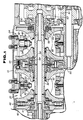
- a continuously variable traction roller transmission includes first and second continuously variable transmission units 22 and 24 within a chamber defined by a casing 10.
- the first continuously variable transmission unit 22 includes an input disc 26, an output disc 28, and a pair of traction rollers 30 for transmitting torque between the two.
- a contact surface of each of the input disc 26 and the output disc 28 with the traction rollers 30 is shaped in a toroid.
- a rotational speed ratio of the input disc 26 to the output disc 28 can continuously be changed by altering a contact state of the traction rollers 30 with the input disc 26, and the output disc 28.
- the second continuously variable transmission unit 24 includes an input disc 32, an output disc 34, and a pair of traction rollers 36 the same as the first continuously variable transmission unit 22.
- the input and output discs 32 and 34 of the second continuously variable transmission unit 24 are disposed in an opposite manner to the input and output discs 26 and 28 of the first continuously variable transmission unit 22. That is, the output disc 28 and the output disc 34 are arranged to be adjacent to each other.
- the input disc 26 of the first continuously variable transmission unit 22 is supported to a rotation shaft 38 at the outer periphery thereof through a ball spline 40.
- a cam flange 42 is disposed on the reverse side of the input disc 26 so as to perform unitary rotation with an input shaft 35 to which engine torque is inputted through a torque converter (not shown).
- An axial position of the cam flange 42 is defined with respect to the rotation shaft 38 through a thrust bearing 41.
- a cam roller 46 is arranged between two cam surfaces of the cam flange 42 and the input disc 26 which face each other.
- the cam roller 46 has a shape to produce a force to urge the input disc 26 to the output disc 28 when relative rotation occurs between the input disc 26 and the cam flange 42.
- the input disc 32 of the second continuously variable transmission unit 24 is operatively connected to the rotation shaft 38 through a ball spline 48.
- the input disc 32 undergoes a force in the direction of the output disc 34 out of four disc springs 51 which in turn undergo a compression out of a loading nut 50 screwed to the rotation shaft 38.
- a disc preloader 49 which will be described hereinafter is disposed between the disc springs 51 and the input disc 32.
- the loading nut 50 is so screwed as to abut on a stopper 99 formed by one end face of the ball spline 48. In that event, the disc springs 51 have a predetermined margin of deformation which is variable in response to input torque.
- the output disc 28 of the first continuously variable transmission unit 22 is rotatably supported on the rotation shaft 38 through a needle bearing 52.
- the output disc 34 of the second continuously variable transmission unit 24 is rotatably supported on the rotation shaft 38 through a needle bearing 53.
- a sleeve 54 is arranged between the output disc 28 and the output disc 34, and splined therewith.
- the sleeve 54 is supported on a member integrally formed with the casing 10 through two angular ball bearings 57 and 58.
- a driving gear 55 is integrally formed with the sleeve 54, and engaged with a follower 60 to perform unitary rotation.
- the follower 60 is operatively connected by a spline to one end of a countershaft 59 arranged in parallel with the rotation shaft 38.
- a gear 61 as integrally formed with the other end of the countershaft 59 can transmit torque to an output gear 63 through an idle gear (not shown).
- the first and second continuously variable transmission units 22 and 24 are mounted to the rotation shaft 38 one after another, and finally restricted in an axial direction thereof by the loading nut 50.
- the loading nut 50 is so screwed as to abut on the stopper 99 of the rotation shaft 38.
- a thickness and a dimension of the disc preloader 49 are previously selected based on a thickness, a spring constant of the disc springs 51, etc. so that, on that condition, the disc springs 51 are in a state of compression with an amount of deflective deformation required to obtain a predetermined preload, and with a predetermined margin of deformation.
- the preload can be set to a predetermined value only by screwing the loading nut 50 up to a stop position.
Landscapes
- Engineering & Computer Science (AREA)
- General Engineering & Computer Science (AREA)
- Mechanical Engineering (AREA)
- Friction Gearing (AREA)
Claims (3)
- Transmission continuellement variable à rouleaux de traction présentant une unité de transmission continuellement variable (24) incluant des disques d'entrée et de sortie (32, 34), le disque d'entrée (32) étant supporté sur un arbre de rotation (38) par une cannelure à billes (48) et une paire de rouleaux de traction (36) qui viennent en contact de friction avec les disques d'entrée et de sortie (32, 34) comprenant :un écrou de mise sous contrainte (50) fixé à l'arbre de rotation (38) ;un moyen formant ressort (51) pour solliciter le disque d'entrée (32) vers le disque de sortie (34), ledit moyen formant ressort (51) étant agencé entre le disque d'entrée (32) et ledit écrou de mise sous contrainte (50) ; etune pièce d'écartement montée en série avec ledit moyen formant ressort (51) dans une direction axiale de l'arbre de rotation (38), ladite pièce d'écartement étant agencée entre le disque d'entrée (32) et ledit moyen formant ressort (51), caractérisée en ce que l'écrou de mise sous contrainte (50), dans l'état assemblé de la transmission, bute sur une butée d'arrêt (99) formée par une face d'extrémité de la cannelure à billes (48), ladite pièce d'écartement est un élément de précontrainte choisi avant (49) d'une épaisseur choisie en fonction de l'état du ressort dudit moyen formant ressort (51) monté dans la transmission de façon à réaliser une force axiale prédéterminée au couple d'entrée zéro et ledit écrou de mise sous contrainte (50) en coopération avec ledit élément de précontrainte choisi (49) forme un espace axial avec une longueur définie d'une manière exacte recevant ledit moyen formant ressort (51) dans l'état partiellement comprimé.
- Transmission continuellement variable à rouleaux de traction selon la revendication 1, caractérisée en ce que ledit moyen formant ressort (51) inclut un ressort à disques.
- Transmission continuellement variable à rouleaux de traction selon la revendication 1, caractérisée en ce que ledit élément de précontrainte (49) inclut un plateau à disques.
Applications Claiming Priority (2)
| Application Number | Priority Date | Filing Date | Title |
|---|---|---|---|
| JP2180576A JP2697261B2 (ja) | 1990-07-10 | 1990-07-10 | 摩擦車式無段変速機 |
| JP180576/90 | 1990-07-10 |
Publications (2)
| Publication Number | Publication Date |
|---|---|
| EP0466113A1 EP0466113A1 (fr) | 1992-01-15 |
| EP0466113B1 true EP0466113B1 (fr) | 1996-01-31 |
Family
ID=16085691
Family Applications (1)
| Application Number | Title | Priority Date | Filing Date |
|---|---|---|---|
| EP91111429A Expired - Lifetime EP0466113B1 (fr) | 1990-07-10 | 1991-07-09 | Variateur continu de vitesse à rouleaux de traction |
Country Status (4)
| Country | Link |
|---|---|
| US (1) | US5144850A (fr) |
| EP (1) | EP0466113B1 (fr) |
| JP (1) | JP2697261B2 (fr) |
| DE (1) | DE69116752T2 (fr) |
Families Citing this family (25)
| Publication number | Priority date | Publication date | Assignee | Title |
|---|---|---|---|---|
| JPH04122848U (ja) * | 1991-04-23 | 1992-11-05 | 日産自動車株式会社 | トロイダル型無段変速機 |
| US5368529A (en) * | 1992-06-29 | 1994-11-29 | Nsk Ltd. | Toroidal type continuously variable transmission |
| GB2274690B (en) * | 1993-02-02 | 1996-05-01 | Nsk Ltd | Toroidal type continuously variable transmission |
| GB9320241D0 (en) * | 1993-10-01 | 1993-11-17 | Greenwood Christopher J | Improvements in or relating to vehicular drivelines including continuously variable-ratio transmissions |
| JP3477764B2 (ja) * | 1993-11-02 | 2003-12-10 | 日本精工株式会社 | ハーフトロイダル型無段変速機 |
| JP3651929B2 (ja) * | 1994-06-23 | 2005-05-25 | 日本精工株式会社 | トロイダル型無段変速機 |
| JP3456267B2 (ja) * | 1994-08-26 | 2003-10-14 | 日本精工株式会社 | トロイダル型無段変速機 |
| JP3435851B2 (ja) * | 1994-11-07 | 2003-08-11 | 日本精工株式会社 | トロイダル型無段変速機 |
| JP3404973B2 (ja) * | 1995-03-29 | 2003-05-12 | 日産自動車株式会社 | トロイダル型無段変速機の変速制御装置 |
| JP3265908B2 (ja) * | 1995-04-24 | 2002-03-18 | 日産自動車株式会社 | トロイダル型無段変速機の変速制御装置 |
| JP3538996B2 (ja) * | 1995-09-22 | 2004-06-14 | 日本精工株式会社 | トロイダル型無段変速機 |
| JP3189677B2 (ja) * | 1996-05-23 | 2001-07-16 | 日産自動車株式会社 | トロイダル型無段変速機 |
| JP3355941B2 (ja) * | 1996-07-16 | 2002-12-09 | 日産自動車株式会社 | トロイダル型無段変速機 |
| US5980421A (en) * | 1997-04-22 | 1999-11-09 | Nsk Ltd. | Toroidal type continuously variable transmission |
| EP0998639B1 (fr) | 1997-07-25 | 2002-06-12 | ZF FRIEDRICHSHAFEN Aktiengesellschaft | Boite de vitesses toroidale variable |
| AU8731998A (en) | 1997-07-26 | 1999-02-16 | Zf Friedrichshafen Ag | Infinitely variable toroidal drive |
| JP4204157B2 (ja) * | 1999-12-06 | 2009-01-07 | 日本精工株式会社 | 四輪駆動車用トロイダル型無段変速装置 |
| JP3783507B2 (ja) | 2000-02-16 | 2006-06-07 | 日本精工株式会社 | トロイダル型無段変速機用ディスクの加工方法 |
| JP3726670B2 (ja) * | 2000-10-25 | 2005-12-14 | 日産自動車株式会社 | トロイダル型無段変速機 |
| JP3714226B2 (ja) * | 2001-10-19 | 2005-11-09 | 日本精工株式会社 | トロイダル型無段変速機 |
| CN1606669B (zh) * | 2003-01-06 | 2011-01-05 | 乌尔里克·罗斯 | 压紧装置和锥形摩擦传动机构以及该锥形摩擦传动机构的运行方法 |
| DE10361546A1 (de) * | 2003-01-06 | 2004-07-15 | Ulrich Dr.-Ing. Rohs | Verfahren zum Betrieb eines Reibgetriebes sowie Reibgetriebe |
| DE10348718A1 (de) * | 2003-06-17 | 2005-06-30 | Ulrich Dr.-Ing. Rohs | Anpresseinrichtung zum Verspannen zweier Getriebeglieder und Getriebe mit einer derartigen Anpresseinrichtung |
| KR101171123B1 (ko) | 2003-06-17 | 2012-08-03 | 울리히 로스 | 마찰 링 기어 및 마찰 링 기어를 작동하기 위한 방법 |
| JP6908501B2 (ja) * | 2017-11-16 | 2021-07-28 | 日本精工株式会社 | トロイダル型無段変速機用押圧装置 |
Family Cites Families (10)
| Publication number | Priority date | Publication date | Assignee | Title |
|---|---|---|---|---|
| US3430504A (en) * | 1966-08-29 | 1969-03-04 | Gen Motors Corp | Transmission |
| GB1583958A (en) * | 1976-08-14 | 1981-02-04 | Lucas Industries Ltd | Axial loading device |
| GB2018894B (en) * | 1978-04-11 | 1983-01-06 | Brie Perry F G De | Fluid pressure operated actuator |
| US4272999A (en) * | 1978-04-11 | 1981-06-16 | National Research Development Corporation | Fluid pressure operated actuator |
| JPH0678780B2 (ja) * | 1986-11-18 | 1994-10-05 | 日産自動車株式会社 | 摩擦車式無段変速機 |
| JPH0611424Y2 (ja) * | 1988-02-02 | 1994-03-23 | 日産自動車株式会社 | 摩擦車式無段変速機 |
| JP2574849B2 (ja) * | 1988-02-23 | 1997-01-22 | 日産自動車株式会社 | トロイダル無段変速機 |
| JP2847711B2 (ja) * | 1988-07-19 | 1999-01-20 | セイコーエプソン株式会社 | 原稿読み取り装置 |
| JPH0672655B2 (ja) * | 1988-12-16 | 1994-09-14 | 日産自動車株式会社 | トロイダル型無段変速機 |
| JPH0672656B2 (ja) * | 1989-03-31 | 1994-09-14 | 日産自動車株式会社 | トロイダル無段変速機のローディングカム装置 |
-
1990
- 1990-07-10 JP JP2180576A patent/JP2697261B2/ja not_active Expired - Lifetime
-
1991
- 1991-06-27 US US07/722,251 patent/US5144850A/en not_active Expired - Lifetime
- 1991-07-09 EP EP91111429A patent/EP0466113B1/fr not_active Expired - Lifetime
- 1991-07-09 DE DE69116752T patent/DE69116752T2/de not_active Expired - Lifetime
Also Published As
| Publication number | Publication date |
|---|---|
| JP2697261B2 (ja) | 1998-01-14 |
| JPH0469439A (ja) | 1992-03-04 |
| DE69116752D1 (de) | 1996-03-14 |
| US5144850A (en) | 1992-09-08 |
| DE69116752T2 (de) | 1996-06-05 |
| EP0466113A1 (fr) | 1992-01-15 |
Similar Documents
| Publication | Publication Date | Title |
|---|---|---|
| EP0466113B1 (fr) | Variateur continu de vitesse à rouleaux de traction | |
| US6159126A (en) | Toroidal continuously variable transmission | |
| US4222246A (en) | Slip clutch | |
| US4541821A (en) | V-belt type stepless transmission | |
| US5027669A (en) | Dual toroidal cavity type continuously variable transmission | |
| US8105171B2 (en) | Torque limiting mechanism | |
| EP1058018B1 (fr) | Embrayage multi-disques avec dispositif hélicoidal pour le réglage de la compression axiale sur les disques | |
| US5967276A (en) | Viscous actuated ball ramp clutch and improved housing therefor | |
| CA1091061A (fr) | Transmission a engrenement constant et a rapport de vitesses variable | |
| CA1067724A (fr) | Transmission motrice | |
| US5014565A (en) | Variable ratio transmission | |
| US20100167868A1 (en) | Friction type continuously variable transmission | |
| US4924728A (en) | Gear shift mechanism with a damper device | |
| US4534236A (en) | Vibration and noise reduction means for a transmission vehicle | |
| EP0674126B1 (fr) | Dispositif d'accouplement pour une transmission automatique | |
| US4969546A (en) | Fluid operated clutch with a directional torque control | |
| US4541820A (en) | V-belt type stepless transmission | |
| US6231473B1 (en) | Toroidal continuously variable transmission | |
| US6248039B1 (en) | Toroidal continuously variable transmission | |
| JP4998081B2 (ja) | 円錐摩擦リング式無段変速装置 | |
| JP3547849B2 (ja) | 遠心クラッチ | |
| JPH0678781B2 (ja) | トロイダル形無段変速機のクリ−プ制御装置 | |
| JPH0637222Y2 (ja) | 摩擦車式無段変速機 | |
| JP4622255B2 (ja) | トロイダル型無段変速機 | |
| JPH0160698B2 (fr) |
Legal Events
| Date | Code | Title | Description |
|---|---|---|---|
| PUAI | Public reference made under article 153(3) epc to a published international application that has entered the european phase |
Free format text: ORIGINAL CODE: 0009012 |
|
| 17P | Request for examination filed |
Effective date: 19910709 |
|
| AK | Designated contracting states |
Kind code of ref document: A1 Designated state(s): DE GB |
|
| 17Q | First examination report despatched |
Effective date: 19940303 |
|
| GRAA | (expected) grant |
Free format text: ORIGINAL CODE: 0009210 |
|
| AK | Designated contracting states |
Kind code of ref document: B1 Designated state(s): DE GB |
|
| REF | Corresponds to: |
Ref document number: 69116752 Country of ref document: DE Date of ref document: 19960314 |
|
| PLBE | No opposition filed within time limit |
Free format text: ORIGINAL CODE: 0009261 |
|
| STAA | Information on the status of an ep patent application or granted ep patent |
Free format text: STATUS: NO OPPOSITION FILED WITHIN TIME LIMIT |
|
| 26N | No opposition filed | ||
| REG | Reference to a national code |
Ref country code: GB Ref legal event code: IF02 |
|
| PGFP | Annual fee paid to national office [announced via postgrant information from national office to epo] |
Ref country code: DE Payment date: 20100707 Year of fee payment: 20 |
|
| PGFP | Annual fee paid to national office [announced via postgrant information from national office to epo] |
Ref country code: GB Payment date: 20100707 Year of fee payment: 20 |
|
| REG | Reference to a national code |
Ref country code: DE Ref legal event code: R071 Ref document number: 69116752 Country of ref document: DE |
|
| REG | Reference to a national code |
Ref country code: DE Ref legal event code: R071 Ref document number: 69116752 Country of ref document: DE |
|
| REG | Reference to a national code |
Ref country code: GB Ref legal event code: PE20 Expiry date: 20110708 |
|
| PG25 | Lapsed in a contracting state [announced via postgrant information from national office to epo] |
Ref country code: GB Free format text: LAPSE BECAUSE OF EXPIRATION OF PROTECTION Effective date: 20110708 |
|
| PG25 | Lapsed in a contracting state [announced via postgrant information from national office to epo] |
Ref country code: DE Free format text: LAPSE BECAUSE OF EXPIRATION OF PROTECTION Effective date: 20110710 |