EP0466159A2 - Zusammengesetzter Magnetkopf - Google Patents
Zusammengesetzter Magnetkopf Download PDFInfo
- Publication number
- EP0466159A2 EP0466159A2 EP91111571A EP91111571A EP0466159A2 EP 0466159 A2 EP0466159 A2 EP 0466159A2 EP 91111571 A EP91111571 A EP 91111571A EP 91111571 A EP91111571 A EP 91111571A EP 0466159 A2 EP0466159 A2 EP 0466159A2
- Authority
- EP
- European Patent Office
- Prior art keywords
- magnetic
- magnetic head
- gap
- composite magnetic
- composite
- Prior art date
- Legal status (The legal status is an assumption and is not a legal conclusion. Google has not performed a legal analysis and makes no representation as to the accuracy of the status listed.)
- Granted
Links
- 239000002131 composite material Substances 0.000 title claims description 59
- 239000010409 thin film Substances 0.000 claims abstract description 57
- 238000006243 chemical reaction Methods 0.000 claims abstract description 54
- 230000002401 inhibitory effect Effects 0.000 claims abstract description 43
- 239000000696 magnetic material Substances 0.000 claims abstract description 15
- 239000010408 film Substances 0.000 claims description 36
- 239000000203 mixture Substances 0.000 claims description 31
- 229910052720 vanadium Inorganic materials 0.000 claims description 8
- 229910052726 zirconium Inorganic materials 0.000 claims description 8
- 229910052759 nickel Inorganic materials 0.000 claims description 7
- 229910052719 titanium Inorganic materials 0.000 claims description 5
- 229910052735 hafnium Inorganic materials 0.000 claims description 4
- 229910052748 manganese Inorganic materials 0.000 claims description 4
- 229910052750 molybdenum Inorganic materials 0.000 claims description 4
- 229910052758 niobium Inorganic materials 0.000 claims description 4
- 229910052715 tantalum Inorganic materials 0.000 claims description 4
- 229910052741 iridium Inorganic materials 0.000 claims description 3
- 229910052742 iron Inorganic materials 0.000 claims description 3
- 229910052763 palladium Inorganic materials 0.000 claims description 3
- 229910052697 platinum Inorganic materials 0.000 claims description 3
- 229910052721 tungsten Inorganic materials 0.000 claims description 3
- 229910052796 boron Inorganic materials 0.000 claims description 2
- 229910052707 ruthenium Inorganic materials 0.000 claims description 2
- 239000011162 core material Substances 0.000 description 40
- XEEYBQQBJWHFJM-UHFFFAOYSA-N iron Substances [Fe] XEEYBQQBJWHFJM-UHFFFAOYSA-N 0.000 description 22
- 238000010438 heat treatment Methods 0.000 description 15
- 229910000859 α-Fe Inorganic materials 0.000 description 14
- 238000002474 experimental method Methods 0.000 description 13
- 239000011521 glass Substances 0.000 description 10
- 239000000463 material Substances 0.000 description 10
- 230000035699 permeability Effects 0.000 description 10
- 238000012360 testing method Methods 0.000 description 9
- 229910000808 amorphous metal alloy Inorganic materials 0.000 description 8
- 230000004907 flux Effects 0.000 description 8
- 229910045601 alloy Inorganic materials 0.000 description 7
- 239000000956 alloy Substances 0.000 description 7
- 230000001965 increasing effect Effects 0.000 description 7
- VYPSYNLAJGMNEJ-UHFFFAOYSA-N Silicium dioxide Chemical compound O=[Si]=O VYPSYNLAJGMNEJ-UHFFFAOYSA-N 0.000 description 6
- 230000005389 magnetism Effects 0.000 description 6
- 239000000758 substrate Substances 0.000 description 6
- 229910052804 chromium Inorganic materials 0.000 description 5
- 238000002360 preparation method Methods 0.000 description 5
- 238000004519 manufacturing process Methods 0.000 description 4
- 239000002184 metal Substances 0.000 description 4
- 229910052751 metal Inorganic materials 0.000 description 4
- 238000000034 method Methods 0.000 description 4
- 229910052757 nitrogen Inorganic materials 0.000 description 4
- 229910000702 sendust Inorganic materials 0.000 description 4
- 229910017082 Fe-Si Inorganic materials 0.000 description 3
- 229910017133 Fe—Si Inorganic materials 0.000 description 3
- 229910052681 coesite Inorganic materials 0.000 description 3
- 230000007797 corrosion Effects 0.000 description 3
- 238000005260 corrosion Methods 0.000 description 3
- 229910052906 cristobalite Inorganic materials 0.000 description 3
- 239000013078 crystal Substances 0.000 description 3
- 239000007789 gas Substances 0.000 description 3
- UCNNJGDEJXIUCC-UHFFFAOYSA-L hydroxy(oxo)iron;iron Chemical compound [Fe].O[Fe]=O.O[Fe]=O UCNNJGDEJXIUCC-UHFFFAOYSA-L 0.000 description 3
- 239000007769 metal material Substances 0.000 description 3
- 239000000700 radioactive tracer Substances 0.000 description 3
- 239000000377 silicon dioxide Substances 0.000 description 3
- 235000012239 silicon dioxide Nutrition 0.000 description 3
- 238000004544 sputter deposition Methods 0.000 description 3
- 229910052682 stishovite Inorganic materials 0.000 description 3
- 229910052905 tridymite Inorganic materials 0.000 description 3
- XKRFYHLGVUSROY-UHFFFAOYSA-N Argon Chemical compound [Ar] XKRFYHLGVUSROY-UHFFFAOYSA-N 0.000 description 2
- IJGRMHOSHXDMSA-UHFFFAOYSA-N Atomic nitrogen Chemical compound N#N IJGRMHOSHXDMSA-UHFFFAOYSA-N 0.000 description 2
- 239000012298 atmosphere Substances 0.000 description 2
- 230000015572 biosynthetic process Effects 0.000 description 2
- 238000010586 diagram Methods 0.000 description 2
- 230000000694 effects Effects 0.000 description 2
- 230000007717 exclusion Effects 0.000 description 2
- 230000001747 exhibiting effect Effects 0.000 description 2
- 230000004927 fusion Effects 0.000 description 2
- 229910021645 metal ion Inorganic materials 0.000 description 2
- 230000002829 reductive effect Effects 0.000 description 2
- 229920006395 saturated elastomer Polymers 0.000 description 2
- 229910017076 Fe Zr Inorganic materials 0.000 description 1
- 229910000640 Fe alloy Inorganic materials 0.000 description 1
- 241000511976 Hoya Species 0.000 description 1
- 229910020018 Nb Zr Inorganic materials 0.000 description 1
- 229910000831 Steel Inorganic materials 0.000 description 1
- 229910007744 Zr—N Inorganic materials 0.000 description 1
- 238000004458 analytical method Methods 0.000 description 1
- 229910052786 argon Inorganic materials 0.000 description 1
- 238000010276 construction Methods 0.000 description 1
- 238000012937 correction Methods 0.000 description 1
- 238000002425 crystallisation Methods 0.000 description 1
- 230000008025 crystallization Effects 0.000 description 1
- 230000005347 demagnetization Effects 0.000 description 1
- 238000009792 diffusion process Methods 0.000 description 1
- 238000007598 dipping method Methods 0.000 description 1
- 238000011156 evaluation Methods 0.000 description 1
- 230000001939 inductive effect Effects 0.000 description 1
- JEIPFZHSYJVQDO-UHFFFAOYSA-N iron(III) oxide Inorganic materials O=[Fe]O[Fe]=O JEIPFZHSYJVQDO-UHFFFAOYSA-N 0.000 description 1
- 230000005415 magnetization Effects 0.000 description 1
- 238000005259 measurement Methods 0.000 description 1
- 238000012986 modification Methods 0.000 description 1
- 230000004048 modification Effects 0.000 description 1
- 239000006060 molten glass Substances 0.000 description 1
- 239000012299 nitrogen atmosphere Substances 0.000 description 1
- 230000036961 partial effect Effects 0.000 description 1
- 229910000889 permalloy Inorganic materials 0.000 description 1
- 230000008569 process Effects 0.000 description 1
- 238000001552 radio frequency sputter deposition Methods 0.000 description 1
- 230000000717 retained effect Effects 0.000 description 1
- 229910052594 sapphire Inorganic materials 0.000 description 1
- 239000010980 sapphire Substances 0.000 description 1
- 239000007858 starting material Substances 0.000 description 1
- 239000010959 steel Substances 0.000 description 1
- 238000006467 substitution reaction Methods 0.000 description 1
- 238000007740 vapor deposition Methods 0.000 description 1
- XLYOFNOQVPJJNP-UHFFFAOYSA-N water Substances O XLYOFNOQVPJJNP-UHFFFAOYSA-N 0.000 description 1
- 238000004804 winding Methods 0.000 description 1
Images



Classifications
-
- G—PHYSICS
- G11—INFORMATION STORAGE
- G11B—INFORMATION STORAGE BASED ON RELATIVE MOVEMENT BETWEEN RECORD CARRIER AND TRANSDUCER
- G11B5/00—Recording by magnetisation or demagnetisation of a record carrier; Reproducing by magnetic means; Record carriers therefor
- G11B5/127—Structure or manufacture of heads, e.g. inductive
- G11B5/187—Structure or manufacture of the surface of the head in physical contact with, or immediately adjacent to the recording medium; Pole pieces; Gap features
- G11B5/1875—"Composite" pole pieces, i.e. poles composed in some parts of magnetic particles and in some other parts of magnetic metal layers
- G11B5/1877—"Composite" pole pieces, i.e. poles composed in some parts of magnetic particles and in some other parts of magnetic metal layers including at least one magnetic thin film
- G11B5/1878—"Composite" pole pieces, i.e. poles composed in some parts of magnetic particles and in some other parts of magnetic metal layers including at least one magnetic thin film disposed immediately adjacent to the transducing gap, e.g. "Metal-In-Gap" structure
-
- G—PHYSICS
- G11—INFORMATION STORAGE
- G11B—INFORMATION STORAGE BASED ON RELATIVE MOVEMENT BETWEEN RECORD CARRIER AND TRANSDUCER
- G11B5/00—Recording by magnetisation or demagnetisation of a record carrier; Reproducing by magnetic means; Record carriers therefor
- G11B5/127—Structure or manufacture of heads, e.g. inductive
- G11B5/187—Structure or manufacture of the surface of the head in physical contact with, or immediately adjacent to the recording medium; Pole pieces; Gap features
- G11B5/1871—Shaping or contouring of the transducing or guiding surface
-
- G—PHYSICS
- G11—INFORMATION STORAGE
- G11B—INFORMATION STORAGE BASED ON RELATIVE MOVEMENT BETWEEN RECORD CARRIER AND TRANSDUCER
- G11B5/00—Recording by magnetisation or demagnetisation of a record carrier; Reproducing by magnetic means; Record carriers therefor
- G11B5/127—Structure or manufacture of heads, e.g. inductive
- G11B5/187—Structure or manufacture of the surface of the head in physical contact with, or immediately adjacent to the recording medium; Pole pieces; Gap features
- G11B5/1871—Shaping or contouring of the transducing or guiding surface
- G11B5/1872—Shaping or contouring of the transducing or guiding surface for improving the form of the electrical signal transduced, e.g. compensation of "contour effect"
- G11B5/1874—Shaping or contouring of the transducing or guiding surface for improving the form of the electrical signal transduced, e.g. compensation of "contour effect" specially adapted for composite pole pieces, e.g. for avoiding "pseudo-gap"
Definitions
- This invention relates to a composite magnetic head and, more particularly, to a composite magnetic head in which a pair of magnetic core halves each including a core block formed of an oxide magnetic material and a soft magnetic thin film formed on each core block are abutted to each other.
- VTRs video tape recorders
- HDDs hard disk devices
- FDDs floppy disk devices
- a composite magnetic head having a magnetic core of the type in which thin films formed of a magnetic metal material of a high saturation magnetic flux density are deposited on core blocks formed of an oxide magnetic material, such as ferrite, and thus exhibiting both the high saturation magnetic flux density and the high magnetic permeability, has come into use in place of conventional ferrite magnetic heads having a low magnetic flux density.
- the composite magnetic head also known as a metal-in-gap (MIG) head
- a reaction layer or diffusion layer is formed on the interface between the ferrite core and the soft magnetic metal material during heating to a higher temperature, such as during crystallization heat treatment of the soft magnetic film or glass fusion, indispensable in the manufacture process of the magnetic head, thus resulting in markedly lowered magnetic properties as the soft magnetic material in the reaction layer.
- the reaction layer acts as a pseudo magnetic gap independently of the normal magnetic head.
- the pseudo magnetic gap formed parallel to the normal magnetic gap, deteriorates the quality of reproduced signals. That is, due to interference with pseudo signals emanating from the pseudo magnetic gap, the reproduced signals exhibit wavy frequency (beat) characteristics having alternate crests and valleys, as shown in Fig. 5.
- the magnitude of waviness is expressed as a ratio in dB of the crests to the valleys of the output signals in the frequency characteristics shown in Fig. 5.
- the presence of the pseudo magnetic gap presents a serious problem because, if the magnitude of the waviness exceeds 1 dB, the composite magnetic head having such playback signal output can no longer be used practically for reproducing magnetic recording.
- the JP Patent KOKAI publication No.1-100714 (1989) discloses a composite magnetic head in which the reaction inhibiting layer containing an oxide(s) of Si, Ti, Cr, Al or the like is formed to a thickness of 20 to 200 ⁇ in the boundary surface of the two magnetic materials.
- the thickness of the reaction inhibiting layer in the above mentioned Kokai Publication needs to be defined in connection with the gap length of the normal magnetic gap.
- no reference is made to this point in determining the thickness of the reaction inhibit layer.
- the present invention provides a composite magnetic head comprising a pair of magnetic core halves each including a core block formed of an oxide magnetic material and a soft magnetic thin film disposed on said core block interposed with a reaction inhibiting layer, said core halves abutting to each other so that a magnetic gap is defined between the ends of said soft magnetic thin films, wherein the magnetic head has a size relation bcd/a ⁇ 0.2 x 10 ⁇ 10 m2 wherein a is a gap length, as measured along the proceeding direction of a magnetic recording medium, c a gap depth as measured in the direction normal to the surface of said magnetic recording medium, d a gap width as measured along the track width of said magnetic recording medium, and b is a thickness of said reaction inhibiting layer.
- the present invention is based on the following recognition.
- a magnetic reluctance of a normal magnetic gap is expressed as r m
- a magnetic reluctance of the reaction inhibiting layer or pseudo magnetic gap as r p
- a magnetic reluctance of other core portionts as r c
- the waviness (beat) B is defined as the ratio of the magnetic reluctance of the pseudo magnetic gap r p to the magnetic reluctance r m of the normal magnetic gap.
- the value of bcd/a for which the waviness (beat) in the reproduced signal in the composite magnetic head having the reaction inhibiting layer functioning as the pseudo gap is not more than a predetermined value (1 dB) is determined experimentally to determine the thickness b of the reaction inhibit layer.
- the thickness of the reaction inhibit layer may be set with a certain degree of freedom as a function of the sizes of the magnetic gap, and the magnitude of the waviness (beat) signal contained in the reproduced signals of a variety of composite magnetic heads having different size magnetic gaps may be easily suppressed to a practically acceptable value of not more than 1 dB.
- the thickness of the reaction inhibiting layer b may be set to a larger value without increasing the waviness signal in the playback signals, so that the reaction inhibiting layer thick enough to prevent reaction between the oxide magnetic material and the non-magnetic film may be obtained.
- a composite magnetic head may be provided in which the waviness signal contained in the reproduced signals is small and a practically acceptable signal quality of the reproduced signals may be maintained.
- Fig. 1 is a perspective view of a magnetic core showing the construction of a composite magnetic head embodying the present invention.
- Fig. 2 is a graph showing measured values of the relation between a waviness signal and the values of a bcd/a defined by sizes a , c and d of a magnetic gap and a thickness b of the reaction inhibiting layer, as confirmed by Experiment 1 of the present invention.
- Fig. 3 is a graph similar to Fig. 2 and showing measured values of data by Experiment 2.
- Fig. 4 is a graph showing frequency characteristics of reproduced signals of the composite magnetic head embodying the present invention.
- Fig. 5 is a graph showing general frequency characteristics of reproduced signals of a conventional composite magnetic head.
- Fig. 6 is a diagram showing a compositional range of a preferred composite magnetic head according to the present invention.
- Fig. 7 is a diagram showing the positive/negative of magnetostriction and the relation between the coercivity Hc and the composition of the soft magnetic thin film prepared in a preparation example of a soft magnetic thin film.
- Fig. 8 is a graph showing the relation between certain manufacture conditions of the soft magnetic thin film and the coercivity Hc and saturation magnetostriction ⁇ s of the soft magnetic thin film manufactured under the manufacture conditions.
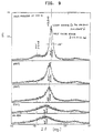
- Fig. 9 is a graph showing the results of X-ray diffractiometry of several thin films manufactured under different heat treatment conditions.
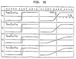
- Fig. 10 is a graph showing alternate BH curves of several thin films having different compositions.
- Fig. 11 is a graph showing IH curves of a thin film before and after heat treatment, as measured by a VSM.
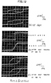
- Fig. 12 is a graph showing ac BH curves of a soft magnetic film having a composition outside the compositional range of a soft magnetic layer of a composite magnetic head embodying the present invention.
- the magnetic head employed in the present experiment is a composite magnetic head having the composition and produced by the method as disclosed in the present Applicant's senior JP Patent Application No. 1-204586 (1989), and is constituted by an MnZn single-crystalline ferrite as a ferrite substrate, an SiO2 layer as a reaction inhibiting layer and a layer of Fe 80.9 Zr 6.5 N 12.6 (atomic percent) as a soft magnetic film. It has been heat treated at a temperature of 550°C.
- Fig. 2 is a graph showing the results of measurement in Experiment 1, where a waviness component in the reproduced signal is represented as a function of bcd/a.
- the ordinate and the abscissa in the graph stand for bcd/a and the waviness (beat) in dB, respectively.
- the gap depth c is variable within the range of from 30 ⁇ m to 0.
- the thickness b of the reaction inhibiting layer is not more than 200 ⁇ .
- the waviness may be suppressed to be not more than 1dB, so that practically acceptable playback signals may be produced.
- the thickness b of the reaction inhibiting layer is not more than 320 ⁇ (b ⁇ 320 ⁇ ) so that the thickness b of the reaction inhibiting layer may be increased up to this value.
- the gap depth c may be reduced to 5 ⁇ m or less with a non-sliding magnetic head, as in a hard disc device (HDD), in which case sufficient reliability of the playback signals may be procured even if the thickness b of the reaction inhibiting layer is increased to this value.
- HDD hard disc device
- the reaction inhibiting layer becomes more effective.
- composition of the starting materials and the method for production as disclosed in our copending JP Patent Application No. 1-204586 (1989) may be employed.
- ferrite is selected as a magnetic oxide material.
- ferrite has a composition MO ⁇ Fe2O3 where M is a divalent metal ion and may for example be Mn2+, Fe2+, Co2+, Ni2+, Cu2+ or Zn2+, but may also be metal ions of higher valencies.
- M is a divalent metal ion and may for example be Mn2+, Fe2+, Co2+, Ni2+, Cu2+ or Zn2+, but may also be metal ions of higher valencies.
- An example of such ferrite is MnZn single-crystalline ferrite.
- SiO2 is used as a reaction inhibiting layer and formed on a core block, formed by the above ferrite, by vapor deposition methods, such as by sputtering.
- an alloy represented by a compositional formula Fe p Zr q N r wherein p, q and r are expressed in atomic percent and satisfy the formulas 0 ⁇ q ⁇ 20 and 0 ⁇ r ⁇ 22 with the exclusion of the ranges q ⁇ 7.5 and r ⁇ 5.
- the value of p, q and r in the above composition satisfy the following formulas: 69 ⁇ p ⁇ 93, 2 ⁇ q ⁇ 15 and 5.5 ⁇ r ⁇ 22.
- compositional range is shown in Fig. 6 by points Q, K, L, U and M.
- the compositional range is defined by line segments interconnecting seven points P (91, 2, 7) Q (92.5, 2, 5.5) R (87, 7.5, 5.5) S (73, 12, 15) T (69, 12, 19) U (69, 9, 22) V (76, 5, 19) in a ternary coordinate system for three components (Fe, Zr, N).
- the compositional range is shown by points P, Q, R, S, T, U and V in fig. 6.
- the crystal grain size is 300 ⁇ or less and the soft magnetic film exhibits uniaxial anisotropy.
- compositional range of the soft magnetic layer is such that 69 ⁇ p ⁇ 93, 2 ⁇ q ⁇ 15 and 5.5 ⁇ r ⁇ 22 better soft magnetism may be achieved.
- the above composition is within a range delimited by line segments interconnecting the above mentioned specific points P, Q, R, S, T, U and V in the ternary coordinate system of the three components (Fe, Zr, N).
- coercivity is particularly low so that the composition may be used advantageously as a core material for a magnetic head.
- Most preferred is the compositional range in which coercivity is 1.5 Oe or lower (or 1 Oe or lower).
- a more preferred compositional range of the soft magnetic layer is a range indicated by Fe s (Zr t N 1-t ) 100-s , 77 ⁇ s ⁇ 88 and 0.3 ⁇ t ⁇ 0.38.
- the compositional range is shown in Fig. 5 by points W, X, Y and Z.
- the coordinates of these points W, X, Y and Z are substantially expressed as W(88, 3.6, 8.4) X(88, 4.56, 7.44) Y(77, 8.74, 14.26) Z(77, 6.9, 16.1)
- the content of Fe is 77 to 88 atomic percent, while the ratio of the content q (in atomic percent) of N to the content r (in atomic percent of Zr in the soft magnetic layer, or the ration r/q, is approximately 1.63 to 2.33.
- the soft magnetic layer of the compositional range exhibits fairly satisfactory soft magnetism with coercivity Hc less than 5 Oe (Hc ⁇ 5Oe).
- part of Zr (for example, 30 atomic percent of Zr constituting the soft magnetic layer) may be replaced by at least one of Hf, Ti, Nb, Ta, V, Mo and W.
- 30 atomic percent, for example, of Fe in the soft magnetic thin film may be replaced by at least one of Co, Ni and Ru.
- the soft magnetic film those having the following composition may be used advantageously:
- Fe p-m M m BqNr where p, q, r and m represent atomic percent, M represents at least one of Co, Ru, Cr, V, Ni, Mn, Pd, Ir and Pt, and B represents at least one of Zr, Hf, Ti, Nb, Ta, Mo and W, and 0 ⁇ m/p ⁇ 0.3 0 ⁇ q ⁇ 20 0 ⁇ r ⁇ 22 provided that the range of q ⁇ 7.5 and r ⁇ 5 is excluded. Substantially the same holds as the case with the system Fe p Zr q N r as shown in Fig.
- This soft magnetic film offers following advantages through the partial substitution of M for Fe.
- the magnetostriction can be exactly adjusted to a value (absolute value) close to zero or increased toward positive direction proportionally to the amount of M elements.
- the saturation magnetic flux density Bs can be further increased (particularly in the case of Co).
- a few Oe (at least about 2 Oe) of the anisotropic magnetic field strength can be given even at a smallest magnetostriction, resulting in high permeability at high frequency (particularly for Co).
- Corrosion resistance can be further improved (particularly in the case with M being Cr, Co, Ni, Pd, Ir, Pt and/or Ru).
- Electric resistivity can be enhanced so as to intere eddy current loss, resulting in high permeability even used at high frequency (particularly in the case with M being V, Cr and/or Mn).
- These thin films were heat-treated in a magnetic field to produce a soft magnetic thin film, of which saturation magnetic flux density Bs and coercivity Hc were measured using an atternate BH tracer with an applied magnetic field of 50Hz and 25 Oe (90 Oe for Hc>25).
- a crystallized glass substrate PEG3130C manufactured by HOYA or a single-crystalline sapphire substrate were used as a substrate. The film thickness for each case was an order of 0.6 ⁇ m.
- the relation between the coercivity Hc and the composition of the soft magnetic thin film produced by the above mentioned preparation example for producing the soft magnetic thin films and the polarity of magnetostriction is shown in Fig. 7, wherein a crystallized glass substrate was used and heat treatment was carried out at 550°C.
- the relation between the conditions for preparing soft magnetic thin films, that is the Fe content in the Fe-Zr alloy target and the N2 content in the sputtering gas, coercivity Hc and saturation magnetostriction ⁇ s, is shown in Fig. 8, wherein a crystallized glass substrate was used and heat treatment was carried out at 550°C.
- a composition Fe 80.9 Zr 6.5 and N 12.6 among the preparation examples of the soft magnetic thin films, the results of X-ray analyses of the as-deposited thin film (not heat treated), and thin films heat treated at 250°, 350°, 450° and 550°C, are shown in Fig. 9, while the results of electrical resistivity are shown in Table 2.
- the crystal grain size of the thin film heat treated at 550°C may be found from the half value width to be approximately 130 ⁇ .
- the as-deposited thin film and the thin film heat treated at 250°C are amorphous, while thin films heat treated at 350°C and 450°C are formed of crystallites and the thin film heat-treated at 550°C are formed of crystallites grown further in the crystal size. It may be presumed that these crystallites contribute to soft magnetism of the thin film, and that generation of these crystallites is ascribable to the presence of N and Zr.
- the value of electrical resistivity of the thin film is lowered by raising the heat-treatment temperature, as may be seen from Table 2, the value is much higher than that for pure iron or permalloy and approximately equal to that of an Fe-Si alloy or sendust even if heat treatment is carried out by raising the temperature to 550°C.
- the film may be used advantageously as a core of a magnetic head because of lower eddy current loss.
- Fig. 10 shows BH curves of several thin films prepared in the same way as in the above mentioned examples of the soft magnetic thin films, as measured with an alternate BH tracer.
- the samples shown in Fig. 10 have been heat-treated at 550°C for 60 minutes in a 10 Torr N2 atmosphere in a 1 kOe magnetic field following the film formation. It is seen from this figure that definite in-plane uniaxial anisotropy has been induced in the thin film by heat treatment in a magnetic field. Therefore, using the hard direction of the thin film as a direction of magnetization, magnetic permeability at a frequency higher than 1 MHz may be increased significantly. Thus the thin film may be used advantageously as a magnetic head material. Also, since the strength of the anisotropic magnetic field Hk is changed within a range of 3 to 18 Oe depending on the composition, the material may be selected in accordance to the magnitude of the magnetic permeability and the occasional frequency range.
- a composition with a still higher value of Hk may also be employed so as not to deteriorate magnetic permeability at a higher frequency.
- Fig. 11 shows the results of an IH curve for a thin film having a composition of Fe 80.9 Zr 6.5 N 12.6 , among the thin films of the above mentioned preparation examples, as obtained by using a VSM.
- (a) shows an IH curve for an as-deposited film and (b) an IH curve for a thin film after heat treatment at 550°C.
- demagnetization field correction was not made and the test sample size of 5mm in diameter 0.63 ⁇ m in thickness was employed.
- the value of coercivity as measured with VSM is smaller by at least one digit than the value obtained with an alternate was determined from the curve in Fig. 11(b) to be approximately 50 mOe.
- the value of 4 ⁇ Ms of the as-deposited thin film is 13.0KG which is slightly smaller than that of the heat-treated thin film.
- the as-deposited film exhibits perpendicular anisotropy (Hk about 4000e) and a higher value of Hc and thus film is only poor in soft magnetic properties.
- a series of soft magnetic films with various compositions are shown in Table 3, in which Fe is partially replaced by the "M" element(s) with the measured values of saturated magnetostriction, saturated magnetic flux density Bs, anisotropy field strength Hk, coercivity Hc, and electric resistivity ⁇ .
- a soft magnetic thin film having a composition outside the compositional range of the soft magnetic layer of the composite magnetic head of the above mentioned preferred embodiment is hereinafter explained.
- amorphous alloy film with a composition of Fe 91.2 Zr 3.9 N 4.9 was formed and heat-treated for one hour at 350°C and 550°C in a magnetic field of 1 kOe.
- Figs. 11(a) to (c) show BH curves, as measured by an alternate BH tracer, of as-deposited amorphous alloy films thus obtained.
- the as-deposited amorphous alloy film, which has not been heat treated, does not exhibit soft magnetism (Fig. 11a).
- the film obtained by heat treating the as-deposited film at 350°C exhibits uniaxial anisotropy (Fig.11b). However, the film obtained by heat treatment at 550°C is deteriorated in its properties (Fig. 11C).
- fusion with molten glass is frequently performed, usually by heating to a temparature in an order of 550°C. If the film of the above composition is employed, satisfactory soft magnetism is not displayed in the ultimately produced magnetic head, through the heating at the time of glass bonding. That is, with the above compositional range, only thermally unstable soft magnetic thin films can be obtained.
- An amorphous layer which is the soft magnetic thin film of the above mentioned composition, formed on a core block of an oxide magnetic material by the interposition of a reaction inhibiting layer, is produced and heat treated at, for example, a temperature of 350 to 650°C, to crystallize part or all of the amorphous layer. Even after such heat treatment, no reaction layer is formed between the ferrite core and the soft magnetic film due to the presence of the reaction inhibiting layer.
- a reaction inhibiting layer is preferably formed by inducing uniaxial magnetic anisotropy by heat treatment in a magnetic field and crystallizing part or all of the above mentioned amorphous layer. The thickness of the reaction inhibiting layer is determined in the following manner.
- the thickness b of the reaction inhibiting layer may be found to be b ⁇ 160 ⁇ , from the formula bcd/a ⁇ 0.2x10 ⁇ 10m2.
- waviness (beat) signals in the reproduced signals not higher than 1dB may be achieved at the time of reproduction of signals recorded on the magnetic recording medium, which is fully acceptable as the performance of the electro-magnetic transducer element at the time of reproduction.
- the thickness b of the reaction inhibiting layer is selected to an extremely large value by being defined in accordance with the above formula, so that a composite magnetic head may be provided in which the reaction inhibiting layer thick enough to prevent reaction between the oxide magnetic material and the soft magnetic film may be formed and in which reproduced signals of practically acceptable quality may be produced.
- FIG. 1 is an enlarged perspective view of an end part of the magnetic core.
- the magnetic core shown therein is formed of separate magnetic core halves 10, 10' fused together by charged sections 5, 5' of fused glass material.
- Ferrite cores 1, 1' of a magnetic material, constituting a major portion of the magnetic core halves 10, 10', include opposing surfaces 11, 11' on abutment sides of the magnetic core halves 10, 10', at the distal ends of which a magnetic gap G is formed, and receded surfaces 12, 12' extending from the opposing surfaces 11, 11' in a direction away from the abutment surfaces.
- soft magnetic metal films 3, 3' On the surfaces of the reaction inhibiting layers 2, 2', there are formed soft magnetic metal films 3, 3', each having a composition Fe 80.9 Zr 6.5 N 12.6 by a thin film forming technique.
- the soft magnetic metal films 3, 3' in conjunction with the core blocks 1, 1' of the magnetic oxide material, constitute a part of the magnetic core of the magnetic core halves 10, 10' of the composite magnetic head.
- the magnetic core halves 10, 10' are placed in abutment with each other, with the soft magnetic metal layers 3, 3' on their surfaces facing each other.
- the core halves 10, 10' are then fused together by the glass materials 5, 5' charged in recesses 32, 32' of the magnetic core halves 10, 10', defined by magnetic layers 3, 3' disposed on the receded surfaces 12, 12' of the ferrite core blocks 1, 1'.
- a winding slot M is formed in a part of the glass bonding region of the magnetic core halves 10, 10' as a through-slot passing through the magnetic core.
- a magnetic gap G formed of a glass material, is formed on an end part faced by a magnetic recording medium of a part of the abutting regions of the magnetic films 3, 3' provided on the opposing surfaces 11, 11' of the ferrite cores 1, 1'.
- a gap length a which is the size if the magnetic gap G as measured in the proceeding direction of the magnetic recording medium placed in opposition to the composite magnetic head, is selected to be 0.2 ⁇
- a track width d which is a width of the magnetic gap G in a direction perpendicular thereto is selected to be 25 ⁇ m
- a gap depth c which is a depth of the magnetic gap as measured in a direction perpendicular to the surface of the recording medium, is selected to be 20 ⁇ m.
- Fig. 4 shows frequency characteristics of reproduced signals outputted from the composite magnetic head of the present example. As shown therein, the waviness (beat) component in the reproduced signal is so small as to be practically negligible, so that the reproduced signals of satisfactory signal quality are obtained.
- the gap length a , gap depth c and the track width d of the magnetic gap are determined by taking into account the recording wavelength and the track width of the magnetic recording medium placed in opposition to the composite magnetic core, as well as the service life of the core against wear, while the thickness b of the reaction inhibiting layer is selected to satisfy the relation bcd/a ⁇ 0.2x10 ⁇ 10m2.
- the thickness b of the reaction inhibiting layer may be selected at a larger value, so that it becomes possible with the reaction inhibiting layer with the thus selected thickness b to prevent reaction between the core block formed of the magnetic oxide material and the thin films formed of the soft magnetic metal material.
Landscapes
- Engineering & Computer Science (AREA)
- Manufacturing & Machinery (AREA)
- Magnetic Heads (AREA)
Applications Claiming Priority (2)
| Application Number | Priority Date | Filing Date | Title |
|---|---|---|---|
| JP18416190 | 1990-07-13 | ||
| JP184161/90 | 1990-07-13 |
Publications (3)
| Publication Number | Publication Date |
|---|---|
| EP0466159A2 true EP0466159A2 (de) | 1992-01-15 |
| EP0466159A3 EP0466159A3 (en) | 1992-12-09 |
| EP0466159B1 EP0466159B1 (de) | 1996-02-28 |
Family
ID=16148436
Family Applications (1)
| Application Number | Title | Priority Date | Filing Date |
|---|---|---|---|
| EP91111571A Expired - Lifetime EP0466159B1 (de) | 1990-07-13 | 1991-07-11 | Zusammengesetzter Magnetkopf |
Country Status (3)
| Country | Link |
|---|---|
| US (1) | US5227940A (de) |
| EP (1) | EP0466159B1 (de) |
| DE (1) | DE69117362T2 (de) |
Cited By (5)
| Publication number | Priority date | Publication date | Assignee | Title |
|---|---|---|---|---|
| GB2268310A (en) * | 1992-06-16 | 1994-01-05 | Samsung Electro Mech | Magnetic Head & Manufacturing Method Thereof |
| US5708370A (en) * | 1995-04-28 | 1998-01-13 | Sony Corporation | Depth sensor which detects grinding depth by means of change and resistance of resistor also ground during grinding |
| US5764450A (en) * | 1994-10-31 | 1998-06-09 | Sony Corporation | Magnetic head |
| US5799389A (en) * | 1994-07-15 | 1998-09-01 | Sony Corporation | Method for producing magnetic head |
| EP1850334A1 (de) * | 2006-04-27 | 2007-10-31 | Heraeus, Inc. | Weichmagnetische Unterschicht in magnetischen Mitteln und Sputtertarget mit weichmagnetischer Legierung |
Families Citing this family (10)
| Publication number | Priority date | Publication date | Assignee | Title |
|---|---|---|---|---|
| JPH05117023A (ja) * | 1991-10-25 | 1993-05-14 | Nec Corp | 磁気ヘツド用非磁性基板および磁気ヘツド |
| JP2586367B2 (ja) * | 1992-04-15 | 1997-02-26 | 日本電気株式会社 | 軟磁性材料とその製造方法および磁気ヘッド |
| JPH0793709A (ja) * | 1993-07-29 | 1995-04-07 | Sony Corp | 磁気ヘッド |
| CN1117180A (zh) * | 1994-03-09 | 1996-02-21 | 株式会社日立制作所 | 磁变电阻效应型磁头及其制造方法 |
| JPH0973605A (ja) * | 1995-09-01 | 1997-03-18 | Matsushita Electric Ind Co Ltd | 磁気ヘッド及びその製造方法と磁気記録再生装置 |
| EP0768640A3 (de) * | 1995-10-13 | 1998-11-11 | Ampex Corporation | Magnetkopf mit kleinem Kern und nicht magnetischem Seitenträger |
| JP2000242912A (ja) * | 1999-02-22 | 2000-09-08 | Mitsumi Electric Co Ltd | 薄膜磁気ヘッド |
| JP2001134904A (ja) * | 1999-11-04 | 2001-05-18 | Sony Corp | 磁気ヘッド |
| US20050150625A1 (en) * | 2000-09-25 | 2005-07-14 | Takashi Ochi | Gravure paper |
| WO2003010759A1 (en) * | 2001-07-23 | 2003-02-06 | Sony Corporation | Magnetic head |
Family Cites Families (7)
| Publication number | Priority date | Publication date | Assignee | Title |
|---|---|---|---|---|
| JPS62210607A (ja) * | 1986-03-12 | 1987-09-16 | Matsushita Electric Ind Co Ltd | 軟磁性合金膜及びその形成法 |
| JPH0731782B2 (ja) * | 1986-10-28 | 1995-04-10 | アルプス電気株式会社 | 浮動式磁気ヘツド |
| JP2513232B2 (ja) * | 1987-05-29 | 1996-07-03 | ソニー株式会社 | 複合磁気ヘッド |
| JP2781849B2 (ja) * | 1987-07-14 | 1998-07-30 | 三洋電機株式会社 | 磁気ヘッド及びその製造方法 |
| JPH0827897B2 (ja) * | 1988-03-09 | 1996-03-21 | 松下電器産業株式会社 | 磁気ヘッド |
| JP2635402B2 (ja) * | 1988-11-02 | 1997-07-30 | アルプス電気株式会社 | 軟磁性合金膜 |
| US5117321A (en) * | 1989-01-26 | 1992-05-26 | Fuji Photo Film Co., Ltd. | Soft magnetic thin film, method for preparing same and magnetic head |
-
1991
- 1991-07-11 DE DE69117362T patent/DE69117362T2/de not_active Expired - Fee Related
- 1991-07-11 US US07/728,498 patent/US5227940A/en not_active Expired - Lifetime
- 1991-07-11 EP EP91111571A patent/EP0466159B1/de not_active Expired - Lifetime
Cited By (6)
| Publication number | Priority date | Publication date | Assignee | Title |
|---|---|---|---|---|
| GB2268310A (en) * | 1992-06-16 | 1994-01-05 | Samsung Electro Mech | Magnetic Head & Manufacturing Method Thereof |
| GB2268310B (en) * | 1992-06-16 | 1996-10-30 | Samsung Electro Mech | Magnetic head & manufacturing method thereof |
| US5799389A (en) * | 1994-07-15 | 1998-09-01 | Sony Corporation | Method for producing magnetic head |
| US5764450A (en) * | 1994-10-31 | 1998-06-09 | Sony Corporation | Magnetic head |
| US5708370A (en) * | 1995-04-28 | 1998-01-13 | Sony Corporation | Depth sensor which detects grinding depth by means of change and resistance of resistor also ground during grinding |
| EP1850334A1 (de) * | 2006-04-27 | 2007-10-31 | Heraeus, Inc. | Weichmagnetische Unterschicht in magnetischen Mitteln und Sputtertarget mit weichmagnetischer Legierung |
Also Published As
| Publication number | Publication date |
|---|---|
| DE69117362D1 (de) | 1996-04-04 |
| DE69117362T2 (de) | 1996-07-11 |
| EP0466159A3 (en) | 1992-12-09 |
| US5227940A (en) | 1993-07-13 |
| EP0466159B1 (de) | 1996-02-28 |
Similar Documents
| Publication | Publication Date | Title |
|---|---|---|
| EP0297776B1 (de) | Weicheisenmagnet-Dünnfilme | |
| US5227940A (en) | Composite magnetic head | |
| EP0620571B1 (de) | Weichmagnetischer Mehrschichtfilm für einen Magnetkopf | |
| US5585984A (en) | Magnetic head | |
| US5663857A (en) | Magnetic head | |
| US5750251A (en) | Multilayered soft magnetic film and magnetic head using the same | |
| EP0105705B1 (de) | Träger für senkrechte magnetische Aufzeichnung | |
| EP0168825A2 (de) | Dünner Film aus magnetischer Legierung | |
| US5862023A (en) | Metal in gap magnetic head having metal magnetic film including precious metal layer | |
| JPH06215325A (ja) | 積層型磁気ヘッドコア | |
| EP0502535B1 (de) | Magnetknopf | |
| JP2775770B2 (ja) | 軟磁性薄膜の製造方法 | |
| JP2798315B2 (ja) | 複合磁気ヘッド | |
| JP3127075B2 (ja) | 軟磁性合金膜と磁気ヘッドおよび軟磁性合金膜の熱膨張係数の調整方法 | |
| JP2523854B2 (ja) | 磁気ヘッド | |
| JPH08115507A (ja) | 磁気ヘッド | |
| US6510023B1 (en) | Magnetic head for high coercive force magnetic recording medium | |
| KR100724013B1 (ko) | 연자성 박막 및 이를 포함한 자기 헤드 | |
| JP2808547B2 (ja) | 複合磁気ヘッド | |
| JPH05226151A (ja) | 磁気ヘッド用高飽和磁束密度・高耐熱性を有する軟磁性合金膜及び磁気ヘッド。 | |
| JPH0555036A (ja) | 軟磁性薄膜およびその製造方法、軟磁性多層膜およびその製造方法ならびに磁気ヘツド | |
| JPH0513223A (ja) | 磁気ヘツド | |
| JPH01100714A (ja) | 複合磁気ヘッド | |
| JPH05174326A (ja) | 磁気ヘッド | |
| JPH0765316A (ja) | 磁気ヘッド |
Legal Events
| Date | Code | Title | Description |
|---|---|---|---|
| PUAI | Public reference made under article 153(3) epc to a published international application that has entered the european phase |
Free format text: ORIGINAL CODE: 0009012 |
|
| AK | Designated contracting states |
Kind code of ref document: A2 Designated state(s): DE GB NL |
|
| PUAL | Search report despatched |
Free format text: ORIGINAL CODE: 0009013 |
|
| AK | Designated contracting states |
Kind code of ref document: A3 Designated state(s): DE GB NL |
|
| 17P | Request for examination filed |
Effective date: 19930602 |
|
| 17Q | First examination report despatched |
Effective date: 19950502 |
|
| GRAA | (expected) grant |
Free format text: ORIGINAL CODE: 0009210 |
|
| AK | Designated contracting states |
Kind code of ref document: B1 Designated state(s): DE GB NL |
|
| REF | Corresponds to: |
Ref document number: 69117362 Country of ref document: DE Date of ref document: 19960404 |
|
| PLBE | No opposition filed within time limit |
Free format text: ORIGINAL CODE: 0009261 |
|
| STAA | Information on the status of an ep patent application or granted ep patent |
Free format text: STATUS: NO OPPOSITION FILED WITHIN TIME LIMIT |
|
| 26N | No opposition filed | ||
| REG | Reference to a national code |
Ref country code: GB Ref legal event code: IF02 |
|
| REG | Reference to a national code |
Ref country code: GB Ref legal event code: 732E |
|
| PGFP | Annual fee paid to national office [announced via postgrant information from national office to epo] |
Ref country code: DE Payment date: 20080717 Year of fee payment: 18 |
|
| PGFP | Annual fee paid to national office [announced via postgrant information from national office to epo] |
Ref country code: NL Payment date: 20080715 Year of fee payment: 18 |
|
| PGFP | Annual fee paid to national office [announced via postgrant information from national office to epo] |
Ref country code: GB Payment date: 20080716 Year of fee payment: 18 |
|
| GBPC | Gb: european patent ceased through non-payment of renewal fee |
Effective date: 20090711 |
|
| NLV4 | Nl: lapsed or anulled due to non-payment of the annual fee |
Effective date: 20100201 |
|
| PG25 | Lapsed in a contracting state [announced via postgrant information from national office to epo] |
Ref country code: GB Free format text: LAPSE BECAUSE OF NON-PAYMENT OF DUE FEES Effective date: 20090711 |
|
| PG25 | Lapsed in a contracting state [announced via postgrant information from national office to epo] |
Ref country code: DE Free format text: LAPSE BECAUSE OF NON-PAYMENT OF DUE FEES Effective date: 20100202 |
|
| PG25 | Lapsed in a contracting state [announced via postgrant information from national office to epo] |
Ref country code: NL Free format text: LAPSE BECAUSE OF NON-PAYMENT OF DUE FEES Effective date: 20100201 |