EP0466171A2 - Appareil d'alimentation en feuilles - Google Patents
Appareil d'alimentation en feuilles Download PDFInfo
- Publication number
- EP0466171A2 EP0466171A2 EP91111626A EP91111626A EP0466171A2 EP 0466171 A2 EP0466171 A2 EP 0466171A2 EP 91111626 A EP91111626 A EP 91111626A EP 91111626 A EP91111626 A EP 91111626A EP 0466171 A2 EP0466171 A2 EP 0466171A2
- Authority
- EP
- European Patent Office
- Prior art keywords
- sheet
- separating
- rotatable
- supply means
- feeding apparatus
- Prior art date
- Legal status (The legal status is an assumption and is not a legal conclusion. Google has not performed a legal analysis and makes no representation as to the accuracy of the status listed.)
- Granted
Links
Images



Classifications
-
- B—PERFORMING OPERATIONS; TRANSPORTING
- B65—CONVEYING; PACKING; STORING; HANDLING THIN OR FILAMENTARY MATERIAL
- B65H—HANDLING THIN OR FILAMENTARY MATERIAL, e.g. SHEETS, WEBS, CABLES
- B65H3/00—Separating articles from piles
- B65H3/46—Supplementary devices or measures to assist separation or prevent double feed
- B65H3/52—Friction retainers acting on under or rear side of article being separated
- B65H3/5207—Non-driven retainers, e.g. movable retainers being moved by the motion of the article
- B65H3/5215—Non-driven retainers, e.g. movable retainers being moved by the motion of the article the retainers positioned under articles separated from the top of the pile
- B65H3/5223—Retainers of the pad-type, e.g. friction pads
Definitions
- the present invention relates to a sheet feeding apparatus which is incorporated into an image forming system such as a copying machine, laser beam printer, facsimile and the like.
- a sheet supply roller 10 comprising a metal core 12 integrally formed with a support shaft 11 and a friction member 13 covering an outer peripheral surface of the metal core is disposed at a downstream side of a sheet stacking support 3 on which a plurality of sheets S are stacked.
- a separating pad 17 formed on a free end of a pivotable support member 81 is urged against the sheet supply roller 10 by a spring force of a separating spring 20.
- the sheet S is urged against the sheet supply roller 10 by means of a pressurizing means comprising an intermediate plate 7 attached to a support plate 6 and a pressure spring 9.
- a pressurizing means comprising an intermediate plate 7 attached to a support plate 6 and a pressure spring 9.
- the spring clutch 40 comprises a control ring 36, a boss 37 and a spring (not shown), and one revolution of the spring clutch 40 is controlled by a solenoid 41.
- a pair of feed rollers 83 comprising a drive roller and a driven roller urged against the drive roller are arranged within a body frame of the apparatus and gears 30a, 30b adapted to transmit a driving force and integrally formed with the drive and driven rollers, respectively are meshed with each other.
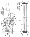
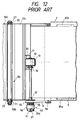
- the pressure between the drive roller 23 and the driven roller 25 of the paired feed rollers 83 is not uniform, but the pressures F at both end portions are stronger than the pressure f at an intermediate portion due to the flexion of the rollers. Accordingly, the pinching force between the rollers is also stronger at the both end portions than at the intermediate portion. Consequently, in the case of a sheet feeding apparatus of frictional separating type, unless a friction separating means is arranged at a central position with respect to a width of the sheet S, the sheet conveying force is unbalanced due to the back tension generated by the sheet supply roller 10, separating pad 17 and the sheet stacking support 3 during the sheet supplying operation, thereby easily causing the skew-feed of the sheet S. In particular, when the sheet supply roller 10 is constituted by a round or cylindrical roller, such back tension will be increased.
- the present invention provides a sheet feeding apparatus comprising a sheet containing means for supporting sheets, a rotatable sheet supply means disposed at a position offset from a center line of a width of the sheet supported by the sheet containing means toward one end of the sheet and adapted to feed out the sheet supported by the sheet containing means, a separating means for separating the sheets one by one between the separating means and the rotatable sheet supply means by abutting against the rotatable sheet supply means, and a pressure releasing means for releasing an urging pressure of the separating means on the way to separate and feed the sheet by means of the separating means.
- the sheet can be supplied on the basis of a one side reference rather than the center reference, only one of the regulating members for regulating the transverse position of the sheet can be shiftable, thus simplifying the construction of the apparatus to make the apparatus inexpensive.
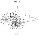
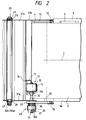
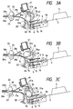
- FIGs. 1 to 3 front parts of sheets S stacked on a sheet stacking support 3 is supported by an intermediate plate 7 for up-and-down movement, and a support member 6 to which the intermediate plate 7 is fixed is pivotally mounted on the sheet stacking support 3 via a support shaft 6a.
- the intermediate plate (stacking means) 7 is biased upwardly by means of a pressure spring (pressurizing means) 9.
- a support member 15 on a free end of which a separating pad 17 is formed is pivotally mounted on a support shaft 16.
- a releasing member 7a is integrally formed on a free end of the intermediate plate 7, and a lower end of the releasing member 7a is opposed to the support member 15.
- a pair of feed rollers 22 comprising a drive roller 23 and a driven roller 25 urged against the drive roller are disposed.
- a pair of guides 21a, 21b and a pair of guides 26a, 26b are disposed at left and right sides of the paired feed rollers 22, respectively.
- the pressure spring 9 and the separating pad 17 are also offset from a center line C of the sheet S (extending in a longitudinal direction of the sheet) toward one lateral edge (left edge in the illustrated embodiment) of the sheet, so that the sheet can be supplied even when a width of the sheet is reduced to some extent.
- the sheets S stacked on the sheet stacking support 3 are urged laterally by a regulating plate 5 for performing the lateral positioning or aligning of the sheets, so that the other lateral edges of the sheets are abutted against an abutment member 3a.
- a peripheral speed of the sheet supply roller 10 is selected to be the same as a peripheral speed of the drive roller 23 of the feed roller pair 22. Further, a peripheral length of the sheet supply roller 10 is selected to be longer than a distance (P - N) between a sheet supplying point (leading end of the sheet) and a nip of the feed roller pair 22 but shorter than a longitudinal length of the sheet S.
- the separating pad 17 and the intermediate plate 7 are in the lowered positions, and the separating pad 17 and the sheets are in a waiting position where they are not contacted by the sheet supply roller 10.
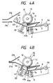
- Figs. 4A and 4B show a second embodiment of the present invention.
- a support member 43 holding the separating pad 17 is pivotally mounted on a support shaft 45 which is disposed at a downstream side of the separating pad 17.
- the intermediate plate 7 When the intermediate plate 7 is lowered, the releasing member 7a is abutted against a free end 43a of the support plate 43, thus lowering the separating pad 17.
- the support shaft 45 may be positioned on a tangential line at a contacting point (separation point) between the separating pad 17 and the sheet supply roller 10.
- a support member 46 holding the separating pad 17 may be mounted within a guide member 47 for up-and-down movement so that the releasing member 7a of the intermediate plate 7 can be abutted against a projection 46a of the support member 46.
- the shifting direction of the separating pad 17 may be selected to coincide with the normal line of the separating pad 17.
- Figs. 5A and 5B show another embodiment of the support shaft 11 for the driving system.
- the sheet feeding means may comprise a pair of regist rollers for determining the timing of the feeding of the sheet.
- Figs. 6A and 6B show a third embodiment of the present invention, where Fig. 6A is a partial plan view of a sheet feeding apparatus according to the third embodiment and Fig. 6B is an elevational sectional view of such apparatus.
- Figs. 7A to 7C show a fourth embodiment of the present invention, wherein the above-mentioned drive roller 52, driven roller 53 and support member 55 constitute a set of skew-feed rollers 51.
- the skew-feed roller set 51 and the abutment member 60 may be disposed at an opposite side of the sheet supply roller 10 with respect to the center line of the sheet.
- the position of sheet supply roller 10, and the positions of the skew-feed roller set 51 and the abutment member 60 may be reversed with respect to the arrangement of Fig. 7A.
- the positions of the skew-feed roller set 51, support shaft 6a and sheet supply roller 10 may be reversed with respect to the arrangement of Fig. 6.
- a sheet stacking support 61 on which the sheets S are stacked may be removably mounted on an attachment portion 2a of a body frame 2 of the sheet feeding apparatus.
- a sheet stacking support 62 may be rotatably supported by a support shaft 72a so that the sheet stacking support 62 can be housed within a containing position 62A in the body frame 2.
- the laser beam emitted from the scanner unit 101 is directed onto the photosensitive drum 103 in the process cartridge 102 via a reflection mirror 107.
- the photosensitive drum 103 is previously charged by the primary charger 104. Accordingly, an electrostatic latent image is formed on the photosensitive drum by illuminating the laser beam thereon and the latent image is visualized by the developing device 105 to form a toner image.
- the sheets S supplied from the sheet stacking support 3 by means of the sheet supply roller 10 are separated one by one by means of the separating pad 17 disposed in confronting relation to the sheet supply roller 10.
- the separated sheet S is guided by the upper and lower guides 21a, 21b and is sent to a pair of regist rollers 113a, 113b which are now temporarily stopped, so that the skew-feed of the sheet is corrected.
- the sheet S is fed to a transfer station in synchronous with a leading end of the toner image formed on the photosensitive drum 103.
- a transfer charger for transferring the toner image formed on the photosensitive drum 103 onto the sheet S is designated by 114.
- Charges having the polarity opposite to that of the toner are given on a back surface of the sheet by the transfer charger 114, and the toner image is gradually transferred from the photosensitive drum 103 to the sheet S.
- the sheet S is separated from the photosensitive drum 103 by charging it to the polarity opposite to that of the transfer charger 114 by means of a separating charger 115.
- the residual toner remaining on the photosensitive drum 103 is removed by the cleaner 106 so that the photosensitive drum can be re-used for the next recording operation.
- the separated sheet S is then fed to a fixing device 117 by means of a conveying means 116.
- the non-fixed and transferred toner image is permanently fixed onto the sheet by the fixing device 117.
- the sheet S is ejected onto an ejector tray 119a or 119b through either of sheet feeding paths selected by a flapper 118.
- a sheet feeding apparatus comprising a sheet supporting means for supporting sheets, a rotatable sheet supply means for feeding out the sheets supported by the sheet supporting means by abutting against the sheet, a separating means for separating the sheets between the separating means and the rotatable sheet supply means by abutting against the rotatable sheet supply means, and a pressure releasing means for releasing an urging force of the separating means on the way to separate and feed the sheet by means of the separating means.
- the present invention further provides an image forming system comprising the above-mentioned sheet feeding apparatus and an image forming means for forming an image on the sheet separated by the separating means.
Landscapes
- Engineering & Computer Science (AREA)
- Mechanical Engineering (AREA)
- Sheets, Magazines, And Separation Thereof (AREA)
- Registering Or Overturning Sheets (AREA)
Applications Claiming Priority (2)
| Application Number | Priority Date | Filing Date | Title |
|---|---|---|---|
| JP185622/90 | 1990-07-13 | ||
| JP2185622A JP2966054B2 (ja) | 1990-07-13 | 1990-07-13 | シート給送装置 |
Publications (3)
| Publication Number | Publication Date |
|---|---|
| EP0466171A2 true EP0466171A2 (fr) | 1992-01-15 |
| EP0466171A3 EP0466171A3 (en) | 1992-05-27 |
| EP0466171B1 EP0466171B1 (fr) | 1996-05-15 |
Family
ID=16174015
Family Applications (1)
| Application Number | Title | Priority Date | Filing Date |
|---|---|---|---|
| EP91111626A Expired - Lifetime EP0466171B1 (fr) | 1990-07-13 | 1991-07-12 | Appareil d'alimentation en feuilles |
Country Status (4)
| Country | Link |
|---|---|
| US (1) | US5386983A (fr) |
| EP (1) | EP0466171B1 (fr) |
| JP (1) | JP2966054B2 (fr) |
| DE (1) | DE69119489T2 (fr) |
Cited By (4)
| Publication number | Priority date | Publication date | Assignee | Title |
|---|---|---|---|---|
| EP0875474A1 (fr) * | 1997-05-02 | 1998-11-04 | Lexmark International, Inc. | Patin d'appui à friction pour la séparation de feuilles |
| US6318716B1 (en) * | 1998-12-24 | 2001-11-20 | Canon Kabushiki Kaisha | Sheet separating apparatus |
| EP1072545A3 (fr) * | 1999-07-29 | 2002-05-15 | Canon Kabushiki Kaisha | Dispositif d'alimentation en feuilles, appareil pour lire des images et appareil de formation d'images |
| EP1369366A3 (fr) * | 2002-06-07 | 2005-07-27 | Canon Kabushiki Kaisha | Appareil d'alimentation de feuilles et appareil de formation d'images |
Families Citing this family (33)
| Publication number | Priority date | Publication date | Assignee | Title |
|---|---|---|---|---|
| JPH0713848U (ja) * | 1993-08-18 | 1995-03-10 | ダイワ精工株式会社 | 自動給紙装置 |
| JP2950158B2 (ja) * | 1993-12-29 | 1999-09-20 | キヤノン株式会社 | 給紙装置及び記録装置 |
| EP0761581B1 (fr) * | 1995-08-28 | 2003-05-02 | Canon Kabushiki Kaisha | Dispositif d'alimentation de feuilles |
| US6032949A (en) * | 1995-10-03 | 2000-03-07 | Canon Kabushiki Kaisha | Sheet conveying device and sheet processing apparatus |
| US5863036A (en) * | 1995-10-20 | 1999-01-26 | Ricoh Company, Ltd. | Sheet feeding device and image forming apparatus having the same |
| JP3056421B2 (ja) * | 1995-10-26 | 2000-06-26 | キヤノン株式会社 | シート材給送装置及び画像形成装置 |
| JP3521102B2 (ja) * | 1996-02-27 | 2004-04-19 | 株式会社リコー | 給紙装置 |
| JP3731260B2 (ja) * | 1996-09-06 | 2006-01-05 | ブラザー工業株式会社 | 給紙装置及びそれを備える画像記録機 |
| US5944305A (en) * | 1997-01-30 | 1999-08-31 | Canon Kabushiki Kaisha | Drive transmitting device, sheet feeding device and image forming apparatus |
| KR200162389Y1 (ko) * | 1997-12-19 | 1999-12-15 | 윤종용 | 캐리지를 이용한 용지공급장치부가 구비된 잉크젯프린터 |
| AU743178B2 (en) * | 1998-04-07 | 2002-01-17 | Umax Data Systems Inc. | Paper-feeding apparatus |
| US5954327A (en) * | 1998-04-06 | 1999-09-21 | Umax Data Systems Inc. | Paper-feeding apparatus |
| US5988627A (en) * | 1998-04-06 | 1999-11-23 | Umax Data Systems Inc. | Paper-feeding apparatus |
| AU741200B2 (en) * | 1998-04-07 | 2001-11-22 | Umax Data Systems Inc. | Paper-feeding apparatus |
| US6398438B1 (en) * | 1998-04-30 | 2002-06-04 | Samsung Electronics Co., Ltd. | Sheet feeding technique for image forming apparatus |
| US6283468B1 (en) * | 1998-08-11 | 2001-09-04 | Brother Kogyo Kabushiki Kaisha | Sheet feeding device |
| US6260840B1 (en) * | 1998-10-14 | 2001-07-17 | Canon Kabushiki Kaisha | Sheet feeding apparatus, image forming apparatus having the same and image reading apparatus having the same |
| US6257569B1 (en) * | 1999-02-24 | 2001-07-10 | Hewlett-Packard Company | Apparatus and method for delivery of sheet media to a printer |
| US6493534B2 (en) | 2000-02-01 | 2002-12-10 | Canon Kabushiki Kaisha | Sheet conveying apparatus and image forming apparatus |
| JP2001213546A (ja) | 2000-02-03 | 2001-08-07 | Canon Inc | シート巻付検出装置及び定着装置及び画像形成装置 |
| TW477748B (en) * | 2000-02-18 | 2002-03-01 | Acer Peripherals Inc | Feeding paper system having taking paper and distributing paper mechanism |
| TW500666B (en) * | 2000-03-03 | 2002-09-01 | Benq Corp | Paper feeding system with paper separation mechanism and paper stop mechanism |
| TW470708B (en) * | 2000-03-17 | 2002-01-01 | Acer Peripherals Inc | Automatic paper feeding system |
| DE60123712T2 (de) * | 2000-08-08 | 2007-08-16 | Ricoh Co., Ltd. | Blattzuführverfahren und Vorrichtung für eine Bilderzeugungsvorrichtung |
| US6658229B2 (en) | 2000-08-30 | 2003-12-02 | Canon Kabushiki Kaisha | Recording material separating apparatus of which separating member is retractable in operative association with guide |
| US6896253B2 (en) * | 2001-05-10 | 2005-05-24 | Canon Kabushiki Kaisha | Sheet material feeding apparatus and recording apparatus |
| US7455288B2 (en) * | 2003-06-16 | 2008-11-25 | Hewlett-Packard Development Company, L.P. | Sheet media input structure |
| KR100608063B1 (ko) * | 2004-09-06 | 2006-08-02 | 삼성전자주식회사 | 화상형성장치의 급지장치 및 이를 적용한 화상형성장치 |
| US20060284369A1 (en) * | 2005-06-07 | 2006-12-21 | Samsung Electronics Co., Ltd. | Unit for and method of registering/feeding paper and image forming apparatus using the same |
| KR20070087712A (ko) * | 2005-06-30 | 2007-08-29 | 삼성전자주식회사 | 급지 장치와 용지 픽업방법 및 이를 채용한 화상 형성 장치 |
| JP4442532B2 (ja) * | 2005-08-22 | 2010-03-31 | 船井電機株式会社 | 画像形成装置 |
| JP5539076B2 (ja) * | 2010-07-07 | 2014-07-02 | キヤノン株式会社 | シート給送装置及び画像形成装置 |
| CN102826397B (zh) * | 2012-09-03 | 2014-12-17 | 瑞安市纸品机械有限公司 | 压痕烫金机续纸机构吸盘角度转换装置 |
Family Cites Families (30)
| Publication number | Priority date | Publication date | Assignee | Title |
|---|---|---|---|---|
| US2363357A (en) * | 1941-02-10 | 1944-11-21 | Anah K Post | Sheet feed |
| US3966189A (en) * | 1974-09-05 | 1976-06-29 | Xerox Corporation | Toggling retard pad |
| US4113245A (en) * | 1977-04-18 | 1978-09-12 | International Business Machines Corporation | Combing wheel feed nip with second sheet restraint |
| JPS55135039A (en) * | 1979-04-11 | 1980-10-21 | Ricoh Co Ltd | Feed paper separation system |
| US4312503A (en) * | 1980-05-27 | 1982-01-26 | Xerox Corporation | Spring-loaded friction retard separator |
| JPS5939641A (ja) * | 1982-08-26 | 1984-03-05 | Ricoh Co Ltd | 給紙装置 |
| JPS5964443A (ja) * | 1982-09-30 | 1984-04-12 | Konishiroku Photo Ind Co Ltd | 給紙装置 |
| JPS5992839A (ja) * | 1982-11-16 | 1984-05-29 | Minolta Camera Co Ltd | 給紙装置 |
| JPS59108646A (ja) * | 1982-12-10 | 1984-06-23 | Canon Inc | シ−ト給送装置 |
| JPS6012426A (ja) * | 1983-06-29 | 1985-01-22 | Toshiba Corp | 給紙機構 |
| JPS6127840A (ja) * | 1984-07-17 | 1986-02-07 | Seiko Epson Corp | 自動給紙装置 |
| JPS61226424A (ja) * | 1985-03-29 | 1986-10-08 | Canon Inc | 給送装置 |
| JPS61229735A (ja) * | 1985-04-05 | 1986-10-14 | Canon Inc | シ−ト材給送装置 |
| JP2557055B2 (ja) * | 1986-09-02 | 1996-11-27 | 富士ゼロックス株式会社 | 紙送り装置 |
| JPS6366032A (ja) * | 1986-09-08 | 1988-03-24 | Ricoh Co Ltd | プリンタの自動給紙装置 |
| JPS6382251A (ja) * | 1986-09-25 | 1988-04-13 | Canon Inc | シ−ト給送装置 |
| JPS63123729A (ja) * | 1986-11-12 | 1988-05-27 | Nec Corp | 給紙装置 |
| JPS642426A (en) * | 1987-06-24 | 1989-01-06 | Nec Corp | Receiving terminal equipment for radio individual calling system |
| JPS644537A (en) * | 1987-06-25 | 1989-01-09 | Toyota Motor Corp | Differential motion control device |
| JPH01118938U (fr) * | 1988-01-30 | 1989-08-11 | ||
| US4809968A (en) * | 1988-03-21 | 1989-03-07 | Xerox Corporation | Side registration with subtle transverse corrugation |
| JPH01281233A (ja) * | 1988-04-28 | 1989-11-13 | Canon Inc | シート給送装置 |
| JPH01294126A (ja) * | 1988-05-20 | 1989-11-28 | Minolta Camera Co Ltd | 給紙装置 |
| JPH0238230A (ja) * | 1988-07-27 | 1990-02-07 | Oki Electric Ind Co Ltd | 用紙分離機構 |
| JPH02138041A (ja) * | 1988-11-17 | 1990-05-28 | Mita Ind Co Ltd | 給紙装置 |
| US5052678A (en) * | 1989-09-13 | 1991-10-01 | Xerox Corporation | Duplex feeder with side shifting inversion |
| US5056604A (en) * | 1990-05-02 | 1991-10-15 | Xerox Corporation | Sheet feeder devices |
| IT1241343B (it) * | 1990-12-10 | 1994-01-10 | Olivetti Canon Ind Spa | Dispositivo per l'introduzione di fogli in una macchina per la riproduzione o la stampa di documenti. |
| US5065998A (en) * | 1990-12-19 | 1991-11-19 | Xerox Corporation | Lateral sheet registration system |
| CN100592452C (zh) * | 2005-07-29 | 2010-02-24 | 松下电器产业株式会社 | 荧光体悬浮液的制备方法、荧光灯、背光单元、直下方式的背光单元以及液晶显示装置 |
-
1990
- 1990-07-13 JP JP2185622A patent/JP2966054B2/ja not_active Expired - Lifetime
-
1991
- 1991-07-12 DE DE69119489T patent/DE69119489T2/de not_active Expired - Fee Related
- 1991-07-12 EP EP91111626A patent/EP0466171B1/fr not_active Expired - Lifetime
-
1993
- 1993-04-06 US US08/044,081 patent/US5386983A/en not_active Expired - Lifetime
Cited By (6)
| Publication number | Priority date | Publication date | Assignee | Title |
|---|---|---|---|---|
| EP0875474A1 (fr) * | 1997-05-02 | 1998-11-04 | Lexmark International, Inc. | Patin d'appui à friction pour la séparation de feuilles |
| US5996989A (en) * | 1997-05-02 | 1999-12-07 | Lexmark International, Inc. | Sheet separator friction pad |
| US6318716B1 (en) * | 1998-12-24 | 2001-11-20 | Canon Kabushiki Kaisha | Sheet separating apparatus |
| EP1072545A3 (fr) * | 1999-07-29 | 2002-05-15 | Canon Kabushiki Kaisha | Dispositif d'alimentation en feuilles, appareil pour lire des images et appareil de formation d'images |
| EP1369366A3 (fr) * | 2002-06-07 | 2005-07-27 | Canon Kabushiki Kaisha | Appareil d'alimentation de feuilles et appareil de formation d'images |
| US7165765B2 (en) | 2002-06-07 | 2007-01-23 | Canon Kabushiki Kaisha | Sheet feeding apparatus and recording apparatus |
Also Published As
| Publication number | Publication date |
|---|---|
| DE69119489T2 (de) | 1996-11-07 |
| US5386983A (en) | 1995-02-07 |
| EP0466171B1 (fr) | 1996-05-15 |
| EP0466171A3 (en) | 1992-05-27 |
| DE69119489D1 (de) | 1996-06-20 |
| JP2966054B2 (ja) | 1999-10-25 |
| JPH0475928A (ja) | 1992-03-10 |
Similar Documents
| Publication | Publication Date | Title |
|---|---|---|
| EP0466171B1 (fr) | Appareil d'alimentation en feuilles | |
| JP3208193B2 (ja) | 画像形成装置のシート給送方法とそのシート給送方法を実施するシート給送装置 | |
| EP0504833A1 (fr) | Appareil pour l'alimentation en feuilles | |
| EP0496398B1 (fr) | Appareil d'alimentation en feuilles | |
| JP2005015199A (ja) | シート給送装置,画像形成装置 | |
| US5860645A (en) | Sheet supplying apparatus | |
| US11613439B2 (en) | Sheet feeding apparatus and image forming apparatus | |
| US6438351B2 (en) | Image forming apparatus having loop forming rollers in accordance with respective sheet feed units | |
| US10183822B2 (en) | Sheet feeding unit, sheet feeding apparatus including sheet feeding unit, and image forming apparatus including sheet feeding apparatus | |
| KR100583288B1 (ko) | 급지 장치 및 화상 형성 장치 | |
| US6145831A (en) | Sheet feeder capable of eliminating overlapping sheet feed | |
| US12091277B2 (en) | Sheet conveyance device and image forming apparatus | |
| US11190657B2 (en) | Document conveying apparatus, image reading apparatus, and image forming apparatus | |
| JP2522058B2 (ja) | シ―ト材給送装置 | |
| JP2522391B2 (ja) | シ―ト材給送装置 | |
| JPH038640A (ja) | 自動給紙装置 | |
| JP3087569B2 (ja) | 給紙装置 | |
| US11982966B2 (en) | Sheet feeding device and image forming apparatus | |
| JP3316398B2 (ja) | シート給送装置 | |
| JP2011042455A (ja) | 給紙装置及び画像形成装置 | |
| JP3524378B2 (ja) | 画像形成装置 | |
| JP3089430B2 (ja) | 再給紙装置 | |
| JP3780870B2 (ja) | 給紙装置および画像形成装置 | |
| JP2796871B2 (ja) | 自動給紙装置 | |
| JP2688038B2 (ja) | シート搬送装置 |
Legal Events
| Date | Code | Title | Description |
|---|---|---|---|
| PUAI | Public reference made under article 153(3) epc to a published international application that has entered the european phase |
Free format text: ORIGINAL CODE: 0009012 |
|
| AK | Designated contracting states |
Kind code of ref document: A2 Designated state(s): DE FR GB IT |
|
| PUAL | Search report despatched |
Free format text: ORIGINAL CODE: 0009013 |
|
| AK | Designated contracting states |
Kind code of ref document: A3 Designated state(s): DE FR GB IT |
|
| 17P | Request for examination filed |
Effective date: 19921013 |
|
| 17Q | First examination report despatched |
Effective date: 19940331 |
|
| GRAA | (expected) grant |
Free format text: ORIGINAL CODE: 0009210 |
|
| AK | Designated contracting states |
Kind code of ref document: B1 Designated state(s): DE FR GB IT |
|
| PG25 | Lapsed in a contracting state [announced via postgrant information from national office to epo] |
Ref country code: IT Free format text: LAPSE BECAUSE OF FAILURE TO SUBMIT A TRANSLATION OF THE DESCRIPTION OR TO PAY THE FEE WITHIN THE PRE;WARNING: LAPSES OF ITALIAN PATENTS WITH EFFECTIVE DATE BEFORE 2007 MAY HAVE OCCURRED AT ANY TIME BEFORE 2007. THE CORRECT EFFECTIVE DATE MAY BE DIFFERENT FROM THE ONE RECORDED.SCRIBED TIME-LIMIT Effective date: 19960515 |
|
| REF | Corresponds to: |
Ref document number: 69119489 Country of ref document: DE Date of ref document: 19960620 |
|
| GRAH | Despatch of communication of intention to grant a patent |
Free format text: ORIGINAL CODE: EPIDOS IGRA |
|
| ET | Fr: translation filed | ||
| PLBE | No opposition filed within time limit |
Free format text: ORIGINAL CODE: 0009261 |
|
| STAA | Information on the status of an ep patent application or granted ep patent |
Free format text: STATUS: NO OPPOSITION FILED WITHIN TIME LIMIT |
|
| 26N | No opposition filed | ||
| REG | Reference to a national code |
Ref country code: GB Ref legal event code: IF02 |
|
| PGFP | Annual fee paid to national office [announced via postgrant information from national office to epo] |
Ref country code: FR Payment date: 20090722 Year of fee payment: 19 |
|
| PGFP | Annual fee paid to national office [announced via postgrant information from national office to epo] |
Ref country code: DE Payment date: 20090731 Year of fee payment: 19 Ref country code: GB Payment date: 20090731 Year of fee payment: 19 |
|
| GBPC | Gb: european patent ceased through non-payment of renewal fee |
Effective date: 20100712 |
|
| REG | Reference to a national code |
Ref country code: FR Ref legal event code: ST Effective date: 20110331 |
|
| PG25 | Lapsed in a contracting state [announced via postgrant information from national office to epo] |
Ref country code: DE Free format text: LAPSE BECAUSE OF NON-PAYMENT OF DUE FEES Effective date: 20110201 |
|
| REG | Reference to a national code |
Ref country code: DE Ref legal event code: R119 Ref document number: 69119489 Country of ref document: DE Effective date: 20110201 |
|
| PG25 | Lapsed in a contracting state [announced via postgrant information from national office to epo] |
Ref country code: FR Free format text: LAPSE BECAUSE OF NON-PAYMENT OF DUE FEES Effective date: 20100802 |
|
| PG25 | Lapsed in a contracting state [announced via postgrant information from national office to epo] |
Ref country code: GB Free format text: LAPSE BECAUSE OF NON-PAYMENT OF DUE FEES Effective date: 20100712 |