EP0466232A1 - Ventilanordnung für Luftregelung in Nahrungsmitteltrocknern - Google Patents
Ventilanordnung für Luftregelung in Nahrungsmitteltrocknern Download PDFInfo
- Publication number
- EP0466232A1 EP0466232A1 EP91201631A EP91201631A EP0466232A1 EP 0466232 A1 EP0466232 A1 EP 0466232A1 EP 91201631 A EP91201631 A EP 91201631A EP 91201631 A EP91201631 A EP 91201631A EP 0466232 A1 EP0466232 A1 EP 0466232A1
- Authority
- EP
- European Patent Office
- Prior art keywords
- arrangement according
- arrangement
- closure component
- component
- cylindrical
- Prior art date
- Legal status (The legal status is an assumption and is not a legal conclusion. Google has not performed a legal analysis and makes no representation as to the accuracy of the status listed.)
- Granted
Links
Images


Classifications
-
- F—MECHANICAL ENGINEERING; LIGHTING; HEATING; WEAPONS; BLASTING
- F26—DRYING
- F26B—DRYING SOLID MATERIALS OR OBJECTS BY REMOVING LIQUID THEREFROM
- F26B21/00—Arrangements for supplying or controlling air or other gases for drying solid materials or objects
- F26B21/30—Controlling, e.g. regulating, parameters of gas supply
-
- F—MECHANICAL ENGINEERING; LIGHTING; HEATING; WEAPONS; BLASTING
- F24—HEATING; RANGES; VENTILATING
- F24F—AIR-CONDITIONING; AIR-HUMIDIFICATION; VENTILATION; USE OF AIR CURRENTS FOR SCREENING
- F24F13/00—Details common to, or for air-conditioning, air-humidification, ventilation or use of air currents for screening
- F24F13/08—Air-flow control members, e.g. louvres, grilles, flaps or guide plates
- F24F13/10—Air-flow control members, e.g. louvres, grilles, flaps or guide plates movable, e.g. dampers
-
- Y—GENERAL TAGGING OF NEW TECHNOLOGICAL DEVELOPMENTS; GENERAL TAGGING OF CROSS-SECTIONAL TECHNOLOGIES SPANNING OVER SEVERAL SECTIONS OF THE IPC; TECHNICAL SUBJECTS COVERED BY FORMER USPC CROSS-REFERENCE ART COLLECTIONS [XRACs] AND DIGESTS
- Y10—TECHNICAL SUBJECTS COVERED BY FORMER USPC
- Y10T—TECHNICAL SUBJECTS COVERED BY FORMER US CLASSIFICATION
- Y10T137/00—Fluid handling
- Y10T137/8158—With indicator, register, recorder, alarm or inspection means
- Y10T137/8225—Position or extent of motion indicator
- Y10T137/8242—Electrical
Definitions
- the present invention relates to a valve arrangement for regulating air in driers for foodstuff products.
- the purpose of the present invention is to achieve an arrangement for air regulation in driers for foodstuffs products which while being structurally more simple will also allow accurate air regulation at the inlet and/or outlet of the drier, eventually allowing forced air input, while completely eliminating losses from the required arrangements.
- a further purpose is to achieve a valve arrangement for air regulation allowing very rapid and easy installation, high operating accuracy and a minimum of quickly completed maintenance.
- valve arrangement for air regulation in driers for foodstuffs products, particularly pasta suitable for location over an aperture made in a wall of the said driers of the type comprising an external support body on the inside of which a moving closure is provided, the said moving closure being actuated selectively in its movement by means of suitable actuator means, characterised in that the said closure component has a taper part turned towards and engaging at least partly within a matching additional housing in a hole in the said outer body of the hollow support.
- a valve arrangement for air regulation in driers for foodstuffs products, particularly pasta is suitable for location within an aperture 11 made in a wall 12 of a drier, within the ceiling or simply a side wall.
- the aperture 11 is of circular shape and the wall 12 of the drier consists of an internal portion 13 in polyurethane between surface facings 14 of fibre glass and in the part turned towards the inside of the drier a further surface facing 15 of stainless steel sheet or aluminium.
- the valve arrangement according to the present invention essentially comprises an external support body, bearing reference 16, inside which a closure component 17 is provided, which is movable and selectively actuated by means of a suitable actuator 18, in the form of a servo motor or a compressed air cylinder with suitable electro pneumatic locator arranged on the outside of the drier.
- the closure component 17 has a taper part 19 which is turned towards a first part 20 of the outer support body 16.
- the first part 20 is bored, is of external cylindrical shape, and has a solid flange 21 at the end turned towards the inside of the drier, to fit upon the internal surface of aperture 11.
- the first portion 20 consists internally of two truncated cone parts 22 and 23 converging towards an internal area of smaller diameter.
- the truncated cone part 23 turned towards the outside of the drier also serves as housing means for at least part of the taper part 19 of the closure component 17.
- the outer surface has a threaded portion 24, of at least the same or smaller diameter than that of aperture 11, over which can be screwed a second flange 25 fully threaded internally.
- the outer support component 16 has in addition a second cylindrical part 26, also hollow, with radial intake apertures 27, axially in line and connected with the said first bored part 20 and covered at one open free end by a plate 28 carrying the said actuator means 18.
- the end of the second cylindrical part 26 turned towards the first part 20 preferably has a flange 29 allowing the fitting of securing screws 30 parallel with the axial direction, together with the flange 25 of the first part 20.
- the plate 28 has a peripheral rim 31 projecting coaxially to the said second cylindrical part 26 and able to surround its circumference at least partly, the plate 28 being linked to the second cylindrical part 26 by means of securing screws 32 located in respective holes, shown in the diagrams and also running parallel with the axial direction.
- the actuator arrangement 18 is a linear movement servo motor from which projects a shaft 33 with a free threaded end 34 suitable for stable insertion into a central axial hole 35 provided in the body of the closure component 17.
- the closure component 17 preferably has in the part turned towards the outside of the drier, or towards the actuator arrangement 18, an annular weight-relieving recess 36.
- annular recess is provided as indicated by the dot and dash line 37, which is coaxial with the said outer support component 16 and able to receive a packing seal 38 shown in dot and dash broken line.
- Fig. 3 shows a further version of a valve arrangement for air regulation according to the present invention entirely similar to that in figs. 1 and 2, in which identical components bear the same reference numbers.
- the difference between the two versions consists mainly in the outer profile of the closure component 17.
- the closure component has a taper part 19 of which the outer surface connecting the apex 40 with the truncated cone housing part 23 has a curved concave profile 39.
- the difference between the first and second versions as described consists essentially in the fact that the air capacity in the first described and illustrated case is of a linear nature, whereas in the second case it is of exponential nature.
- An arrangement according to the present invention is thus particularly suited when designed according to the first version, for large air capacities, whereas with the design according to the second version, it is particularly suited for small volumes of air.
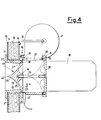
- Fig. 4 shows a further version in which a forced air supply or extraction is provided for.
- a single radial aperture 27 is provided against which extractor and/or ventilator means 41 are placed allowing forced drier inlet or outlet air movement.
- the operating signal to actuate the extractor and/or ventilator means 41 is provided by sensor means 42 able to detect the presence or otherwise of a widened lower end 43 of the closure component 17.
- the actuator arrangement 18 moves the closure component 17 from its bearing contact position closing the regulator arrangement, the said widened lower end 43 passing before the sensor arrangement 42 triggers actuation of the extraction and/or ventilator arrangement 41 thus achieving forced air movement.
- valve arrangement for air regulation in driers for foodstuffs products, particularly pasta, according to the present invention thus has considerable advantages in relation to known types of arrangement.
- the mechanical design allows quick and accurate fitting, only requiring a circular hole in the wall or ceiling of the drier.
- the mechanical design is particularly simple and consequently allows highly cost effective manufacture.
Landscapes
- Engineering & Computer Science (AREA)
- Mechanical Engineering (AREA)
- General Engineering & Computer Science (AREA)
- Chemical & Material Sciences (AREA)
- Combustion & Propulsion (AREA)
- Drying Of Solid Materials (AREA)
- Valve Housings (AREA)
- Fluid-Driven Valves (AREA)
Priority Applications (1)
| Application Number | Priority Date | Filing Date | Title |
|---|---|---|---|
| AT91201631T ATE100571T1 (de) | 1990-07-09 | 1991-06-25 | Ventilanordnung fuer luftregelung in nahrungsmitteltrocknern. |
Applications Claiming Priority (2)
| Application Number | Priority Date | Filing Date | Title |
|---|---|---|---|
| IT2146290U | 1990-07-09 | ||
| IT21462U IT220043Z2 (it) | 1990-07-09 | 1990-07-09 | Dispositivo a valvola per la regolazione di aria in essiccatoi per prodotti alimentari |
Publications (2)
| Publication Number | Publication Date |
|---|---|
| EP0466232A1 true EP0466232A1 (de) | 1992-01-15 |
| EP0466232B1 EP0466232B1 (de) | 1994-01-19 |
Family
ID=11182161
Family Applications (1)
| Application Number | Title | Priority Date | Filing Date |
|---|---|---|---|
| EP91201631A Expired - Lifetime EP0466232B1 (de) | 1990-07-09 | 1991-06-25 | Ventilanordnung für Luftregelung in Nahrungsmitteltrocknern |
Country Status (6)
| Country | Link |
|---|---|
| US (1) | US5193783A (de) |
| EP (1) | EP0466232B1 (de) |
| JP (1) | JPH04249682A (de) |
| AT (1) | ATE100571T1 (de) |
| DE (1) | DE69101037T2 (de) |
| IT (1) | IT220043Z2 (de) |
Cited By (1)
| Publication number | Priority date | Publication date | Assignee | Title |
|---|---|---|---|---|
| DE102007040731A1 (de) * | 2006-11-11 | 2009-03-05 | Naber Holding Gmbh & Co. Kg | Mauerkasten |
Families Citing this family (2)
| Publication number | Priority date | Publication date | Assignee | Title |
|---|---|---|---|---|
| DE202005010912U1 (de) † | 2005-07-12 | 2005-11-10 | Berbel Ablufttechnik Gmbh | Luftführungskasten |
| US20110006070A1 (en) * | 2009-07-09 | 2011-01-13 | Helgesen Design Services, Llc | Fluid Tank Having Integrated Shut-Off |
Citations (7)
| Publication number | Priority date | Publication date | Assignee | Title |
|---|---|---|---|---|
| NL24189C (de) * | 1900-01-01 | |||
| US1349568A (en) * | 1917-11-05 | 1920-08-17 | Gammel Karl | Process of drying macaroni and other edible pastes |
| FR1569819A (de) * | 1968-04-04 | 1969-06-06 | ||
| FR2030759A5 (de) * | 1969-12-05 | 1970-11-13 | Faure Hugues | |
| GB1244725A (en) * | 1967-11-30 | 1971-09-02 | Osma Plastics Ltd | Valves |
| FR2137747A1 (de) * | 1971-05-11 | 1972-12-29 | Glent & Co As | |
| EP0208179A1 (de) * | 1985-07-01 | 1987-01-14 | Marius Thiebaud | Selbsttätige Klappe zur Regelung einer aus einem Raum durch eine Zwangsentlüftung abgesaugten Luftmenge |
Family Cites Families (6)
| Publication number | Priority date | Publication date | Assignee | Title |
|---|---|---|---|---|
| US3065949A (en) * | 1960-01-13 | 1962-11-27 | Frees Joseph H De | Chemical emergency valve |
| US4251049A (en) * | 1979-01-22 | 1981-02-17 | Muehl Herman D | Tank valve apparatus |
| US4456220A (en) * | 1981-06-01 | 1984-06-26 | Acf Industries, Incorporated | Nozzle assembly for top operating rod |
| US4440379A (en) * | 1982-04-16 | 1984-04-03 | Acf Industries, Incorporated | Bottom operator for top operated bottom installed tank car valve assembly |
| FR2531176A1 (fr) * | 1982-07-29 | 1984-02-03 | Framatome Sa | Dispositif de detection du fonctionnement d'une soupape |
| US4934403A (en) * | 1989-04-10 | 1990-06-19 | Betts Industries, Inc. | Readily inspectable and cleanable emergency valve for storage tank |
-
1990
- 1990-07-09 IT IT21462U patent/IT220043Z2/it active IP Right Grant
-
1991
- 1991-06-25 EP EP91201631A patent/EP0466232B1/de not_active Expired - Lifetime
- 1991-06-25 DE DE69101037T patent/DE69101037T2/de not_active Expired - Fee Related
- 1991-06-25 AT AT91201631T patent/ATE100571T1/de not_active IP Right Cessation
- 1991-07-03 US US07/725,468 patent/US5193783A/en not_active Expired - Fee Related
- 1991-07-08 JP JP3192778A patent/JPH04249682A/ja active Pending
Patent Citations (7)
| Publication number | Priority date | Publication date | Assignee | Title |
|---|---|---|---|---|
| NL24189C (de) * | 1900-01-01 | |||
| US1349568A (en) * | 1917-11-05 | 1920-08-17 | Gammel Karl | Process of drying macaroni and other edible pastes |
| GB1244725A (en) * | 1967-11-30 | 1971-09-02 | Osma Plastics Ltd | Valves |
| FR1569819A (de) * | 1968-04-04 | 1969-06-06 | ||
| FR2030759A5 (de) * | 1969-12-05 | 1970-11-13 | Faure Hugues | |
| FR2137747A1 (de) * | 1971-05-11 | 1972-12-29 | Glent & Co As | |
| EP0208179A1 (de) * | 1985-07-01 | 1987-01-14 | Marius Thiebaud | Selbsttätige Klappe zur Regelung einer aus einem Raum durch eine Zwangsentlüftung abgesaugten Luftmenge |
Cited By (2)
| Publication number | Priority date | Publication date | Assignee | Title |
|---|---|---|---|---|
| DE102007040731A1 (de) * | 2006-11-11 | 2009-03-05 | Naber Holding Gmbh & Co. Kg | Mauerkasten |
| US8721410B2 (en) | 2006-11-11 | 2014-05-13 | Naber Holding Gmbh & Co. Kg | Wall sleeve |
Also Published As
| Publication number | Publication date |
|---|---|
| IT9021462V0 (it) | 1990-07-09 |
| US5193783A (en) | 1993-03-16 |
| IT9021462U1 (it) | 1992-01-09 |
| JPH04249682A (ja) | 1992-09-04 |
| ATE100571T1 (de) | 1994-02-15 |
| EP0466232B1 (de) | 1994-01-19 |
| DE69101037T2 (de) | 1994-05-26 |
| DE69101037D1 (de) | 1994-03-03 |
| IT220043Z2 (it) | 1993-06-09 |
Similar Documents
| Publication | Publication Date | Title |
|---|---|---|
| US4346611A (en) | Insertion regulator for pressurized pipelines | |
| US3964507A (en) | Slide valve with integrated removable internals | |
| US4585207A (en) | Expanding gate valve with pneumatic actuator | |
| US4044631A (en) | Rotary actuator | |
| US4478241A (en) | Solenoid actuated valve blocks for glassware forming machines | |
| US4911404A (en) | Electronically operated expansion valve | |
| US9874292B2 (en) | Diaphragm actuators having adjustable actuation force | |
| US5170693A (en) | Rotary actuator device with a free floating piston | |
| US4739924A (en) | Air volume regulator valve | |
| EP0466232B1 (de) | Ventilanordnung für Luftregelung in Nahrungsmitteltrocknern | |
| US20060266962A1 (en) | Vacuum regulating valve | |
| EP0081910B1 (de) | Motorisch angetriebenes Durchflussregelventil | |
| EP1803980B1 (de) | Ventil mit Hohlkolben | |
| US4285493A (en) | Valve operator | |
| EP0205310B1 (de) | Auspuffbremse | |
| US7537022B2 (en) | Valve actuator assembly | |
| US9500295B2 (en) | Sleeve valve with sync cam | |
| US4379543A (en) | Vane type valve actuator | |
| EP2867564B1 (de) | Axialflüssigkeitsventile mit linearen aktuatoren | |
| US4374485A (en) | Single annular membrane type of pneumatic positioner | |
| US6276393B1 (en) | Position sensing system for butterfly valves | |
| US4531544A (en) | Fire flap arrangement | |
| US3734458A (en) | Gate valve | |
| US2983478A (en) | Butterfly valves | |
| JP7619693B1 (ja) | 筐体 |
Legal Events
| Date | Code | Title | Description |
|---|---|---|---|
| PUAI | Public reference made under article 153(3) epc to a published international application that has entered the european phase |
Free format text: ORIGINAL CODE: 0009012 |
|
| AK | Designated contracting states |
Kind code of ref document: A1 Designated state(s): AT BE CH DE DK ES FR GB GR IT LI LU NL SE |
|
| 17P | Request for examination filed |
Effective date: 19920124 |
|
| 17Q | First examination report despatched |
Effective date: 19920713 |
|
| GRAA | (expected) grant |
Free format text: ORIGINAL CODE: 0009210 |
|
| ITF | It: translation for a ep patent filed | ||
| AK | Designated contracting states |
Kind code of ref document: B1 Designated state(s): AT BE CH DE DK ES FR GB GR IT LI LU NL SE |
|
| PG25 | Lapsed in a contracting state [announced via postgrant information from national office to epo] |
Ref country code: SE Effective date: 19940119 Ref country code: NL Effective date: 19940119 Ref country code: GR Free format text: LAPSE BECAUSE OF FAILURE TO SUBMIT A TRANSLATION OF THE DESCRIPTION OR TO PAY THE FEE WITHIN THE PRESCRIBED TIME-LIMIT Effective date: 19940119 Ref country code: ES Free format text: THE PATENT HAS BEEN ANNULLED BY A DECISION OF A NATIONAL AUTHORITY Effective date: 19940119 Ref country code: DK Effective date: 19940119 Ref country code: BE Effective date: 19940119 Ref country code: AT Effective date: 19940119 |
|
| REF | Corresponds to: |
Ref document number: 100571 Country of ref document: AT Date of ref document: 19940215 Kind code of ref document: T |
|
| REF | Corresponds to: |
Ref document number: 69101037 Country of ref document: DE Date of ref document: 19940303 |
|
| ET | Fr: translation filed | ||
| PG25 | Lapsed in a contracting state [announced via postgrant information from national office to epo] |
Ref country code: LU Free format text: LAPSE BECAUSE OF NON-PAYMENT OF DUE FEES Effective date: 19940630 |
|
| NLV1 | Nl: lapsed or annulled due to failure to fulfill the requirements of art. 29p and 29m of the patents act | ||
| PLBE | No opposition filed within time limit |
Free format text: ORIGINAL CODE: 0009261 |
|
| STAA | Information on the status of an ep patent application or granted ep patent |
Free format text: STATUS: NO OPPOSITION FILED WITHIN TIME LIMIT |
|
| 26N | No opposition filed | ||
| PG25 | Lapsed in a contracting state [announced via postgrant information from national office to epo] |
Ref country code: GB Effective date: 19950625 |
|
| GBPC | Gb: european patent ceased through non-payment of renewal fee |
Effective date: 19950625 |
|
| PGFP | Annual fee paid to national office [announced via postgrant information from national office to epo] |
Ref country code: FR Payment date: 19960524 Year of fee payment: 6 |
|
| PGFP | Annual fee paid to national office [announced via postgrant information from national office to epo] |
Ref country code: DE Payment date: 19960813 Year of fee payment: 6 |
|
| PGFP | Annual fee paid to national office [announced via postgrant information from national office to epo] |
Ref country code: CH Payment date: 19970930 Year of fee payment: 7 |
|
| PG25 | Lapsed in a contracting state [announced via postgrant information from national office to epo] |
Ref country code: FR Free format text: LAPSE BECAUSE OF NON-PAYMENT OF DUE FEES Effective date: 19980227 |
|
| PG25 | Lapsed in a contracting state [announced via postgrant information from national office to epo] |
Ref country code: DE Free format text: LAPSE BECAUSE OF NON-PAYMENT OF DUE FEES Effective date: 19980303 |
|
| REG | Reference to a national code |
Ref country code: FR Ref legal event code: ST |
|
| REG | Reference to a national code |
Ref country code: FR Ref legal event code: ST |
|
| PG25 | Lapsed in a contracting state [announced via postgrant information from national office to epo] |
Ref country code: LI Free format text: LAPSE BECAUSE OF NON-PAYMENT OF DUE FEES Effective date: 19980630 Ref country code: CH Free format text: LAPSE BECAUSE OF NON-PAYMENT OF DUE FEES Effective date: 19980630 |
|
| REG | Reference to a national code |
Ref country code: CH Ref legal event code: PL |
|
| PG25 | Lapsed in a contracting state [announced via postgrant information from national office to epo] |
Ref country code: IT Free format text: LAPSE BECAUSE OF NON-PAYMENT OF DUE FEES;WARNING: LAPSES OF ITALIAN PATENTS WITH EFFECTIVE DATE BEFORE 2007 MAY HAVE OCCURRED AT ANY TIME BEFORE 2007. THE CORRECT EFFECTIVE DATE MAY BE DIFFERENT FROM THE ONE RECORDED. Effective date: 20050625 |