EP0466373A2 - Dispositif de fixation - Google Patents
Dispositif de fixation Download PDFInfo
- Publication number
- EP0466373A2 EP0466373A2 EP91305920A EP91305920A EP0466373A2 EP 0466373 A2 EP0466373 A2 EP 0466373A2 EP 91305920 A EP91305920 A EP 91305920A EP 91305920 A EP91305920 A EP 91305920A EP 0466373 A2 EP0466373 A2 EP 0466373A2
- Authority
- EP
- European Patent Office
- Prior art keywords
- holder
- cavity
- arrangement according
- annular discs
- fastening arrangement
- Prior art date
- Legal status (The legal status is an assumption and is not a legal conclusion. Google has not performed a legal analysis and makes no representation as to the accuracy of the status listed.)
- Withdrawn
Links
Images

Classifications
-
- F—MECHANICAL ENGINEERING; LIGHTING; HEATING; WEAPONS; BLASTING
- F16—ENGINEERING ELEMENTS AND UNITS; GENERAL MEASURES FOR PRODUCING AND MAINTAINING EFFECTIVE FUNCTIONING OF MACHINES OR INSTALLATIONS; THERMAL INSULATION IN GENERAL
- F16L—PIPES; JOINTS OR FITTINGS FOR PIPES; SUPPORTS FOR PIPES, CABLES OR PROTECTIVE TUBING; MEANS FOR THERMAL INSULATION IN GENERAL
- F16L3/00—Supports for pipes, cables or protective tubing, e.g. hangers, holders, clamps, cleats, clips, brackets
- F16L3/22—Supports for pipes, cables or protective tubing, e.g. hangers, holders, clamps, cleats, clips, brackets specially adapted for supporting a number of parallel pipes at intervals
- F16L3/223—Supports for pipes, cables or protective tubing, e.g. hangers, holders, clamps, cleats, clips, brackets specially adapted for supporting a number of parallel pipes at intervals each support having one transverse base for supporting the pipes
-
- F—MECHANICAL ENGINEERING; LIGHTING; HEATING; WEAPONS; BLASTING
- F16—ENGINEERING ELEMENTS AND UNITS; GENERAL MEASURES FOR PRODUCING AND MAINTAINING EFFECTIVE FUNCTIONING OF MACHINES OR INSTALLATIONS; THERMAL INSULATION IN GENERAL
- F16L—PIPES; JOINTS OR FITTINGS FOR PIPES; SUPPORTS FOR PIPES, CABLES OR PROTECTIVE TUBING; MEANS FOR THERMAL INSULATION IN GENERAL
- F16L55/00—Devices or appurtenances for use in, or in connection with, pipes or pipe systems
- F16L55/02—Energy absorbers; Noise absorbers
- F16L55/033—Noise absorbers
- F16L55/035—Noise absorbers in the form of specially adapted hangers or supports
Definitions
- the invention relates to a fastening device with a clip for elongate articles, particularly for the retention of fuel lines on a car engine block having a holding arrangement.
- Fastening devices used until now in practice allow movement of the clip holding the fuel lines by using a slot and have the drawback that such relative movement leads to undesirable friction which destroys the coating, for example of a fastening bracket, and therefore gives rise to the risk of corrosion.
- a fastening device with a clip for elongate articles is provided with two axially spaced, mutually joined annular discs which define between themselves a cavity for receiving a holder in the cavity with clearance fit, in that a receiving orifice for an expanding foot of the clip housing is provided on the holder and in that internal rings which cover the cavity on both sides are fixed on the two annular discs.
- an important advantage of this device according to the invention is that the fuel lines are always held in their correct position without having to participate in the vibrations of an engine, for example when starting or during acceleration.
- the holder on which the clip holding the fuel lines is fixed is movable within limits in a horizontal plane and in all directions in the cavity between the two annular discs, the limits to this movement being defined by the webs joining the two annular discs together and by the expanding head being able to touch the internal surface of the internal ring and the webs thereof.
- the fastening device is made entirely of plastics material and is produced by injection moulding.
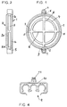
- the fastening device consists of an upper annular disc 1 and a lower annular disc 2, an internal ring 4 being secured inside the central passage, this ring 4 having webs 6 and projections 8 serving to fix the internal ring 4 to the respective annular disc 1, 2.
- Each annular disc 1, 2 consists of two portions 1a, 1b and 2a, 2b. However, as shown in Figure 2, these portions which have the same internal diameter are offset in their outer periphery so that the respective outer portion 1a, 2a of the two annular discs have a smaller external diameter than the associated portions 1b, 2b. It should be emphasised that the individual portions are not separate components, but that the annular discs are in one piece and are joined together at four points by means of webs 5.
- a cavity 3 having a purpose which will be described hereinafter is therefore formed between the two annular discs 1, 2, as shown, in particular, in Figure 2.
- a cross-shaped holder 12 of which the spokes 14 are mutually spaced at 45° and having pointed or rounded ends, is also provided.
- the axial thickness of the cross is somewhat smaller than the depth of the cavity.
- the holder has also a receiving orifice 13 for an expanding foot 11 ( Figure 4) which is provided on the base 10 of a clip 9 adapted to receive the actual fuel lines.
- Expanding foot 11 makes clip housing 10 detachable from the cross-shaped holder so that, for example, the removal of defective fuel lines is facilitated.
- the fastening arrangement as shown in Figure 1 can be produced, for example by injection moulding of a suitable plastics material and the fastening device consists of three separate components, namely of the annular discs 1, 2 with integrated internal ring 4, the cross-shaped holder 12 and also the clip housing 10.
- the two internal rings 4 provided in each case on the two annular discs 1, 2 serve to cover the holder when it is installed.
Landscapes
- Engineering & Computer Science (AREA)
- General Engineering & Computer Science (AREA)
- Mechanical Engineering (AREA)
- Fuel-Injection Apparatus (AREA)
Applications Claiming Priority (2)
| Application Number | Priority Date | Filing Date | Title |
|---|---|---|---|
| DE19904022173 DE4022173A1 (de) | 1990-07-12 | 1990-07-12 | Befestigungsvorrichtung |
| DE4022173 | 1990-07-12 |
Publications (2)
| Publication Number | Publication Date |
|---|---|
| EP0466373A2 true EP0466373A2 (fr) | 1992-01-15 |
| EP0466373A3 EP0466373A3 (en) | 1992-02-26 |
Family
ID=6410135
Family Applications (1)
| Application Number | Title | Priority Date | Filing Date |
|---|---|---|---|
| EP19910305920 Withdrawn EP0466373A3 (en) | 1990-07-12 | 1991-07-01 | Fastening device |
Country Status (2)
| Country | Link |
|---|---|
| EP (1) | EP0466373A3 (fr) |
| DE (1) | DE4022173A1 (fr) |
Cited By (1)
| Publication number | Priority date | Publication date | Assignee | Title |
|---|---|---|---|---|
| DE102007060030A1 (de) * | 2007-06-01 | 2008-12-04 | Airbus Deutschland Gmbh | Vorrichtung zur Halterung von Systemen |
Families Citing this family (2)
| Publication number | Priority date | Publication date | Assignee | Title |
|---|---|---|---|---|
| DE19547070C2 (de) * | 1995-12-16 | 1998-07-02 | Bayerische Motoren Werke Ag | Befestigungsvorrichtung mit einem Halteelement für eine Leitung |
| DE29721023U1 (de) * | 1997-11-27 | 1998-01-22 | Armaturenfabrik Hermann Voss GmbH + Co, 51688 Wipperfürth | Rastbarer Leitungsverbinder insbesondere für Kraftstoffleitungen |
Family Cites Families (13)
| Publication number | Priority date | Publication date | Assignee | Title |
|---|---|---|---|---|
| DE864338C (de) * | 1951-09-21 | 1953-01-22 | Essener Hochdruck Rohrleitungs | Bewegliche Lagerung von Lasten, z. B. von Rohrleitungen |
| DE3002031C2 (de) * | 1980-01-21 | 1982-07-15 | United-Carr Gmbh, 6000 Frankfurt | Halteelement für mindestens eine Rohrleitung, insbesondere Benzinleitung bei einem Kraftfahrzeug |
| DE8100199U1 (de) * | 1981-01-08 | 1982-01-21 | J.H. Benecke Gmbh, 3000 Hannover | Befestigungselement für Kraftfahrzeug-Innenverkleidungen |
| US4568215A (en) * | 1983-11-21 | 1986-02-04 | Illinois Tool Works Inc. | Laterally adjustable fastening assembly |
| DE3416262A1 (de) * | 1984-05-02 | 1985-11-07 | TRW United-Carr GmbH, 6000 Frankfurt | Kunststoffhalteteil |
| DE3602625C1 (de) * | 1986-01-29 | 1987-03-05 | Bayerische Motoren Werke Ag | Haltevorrichtung fuer mindestens eine Leitung,insbesondere eine Kraftstoffleitung an einem Kraftfahrzeug |
| DE3644334A1 (de) * | 1986-12-23 | 1989-03-23 | United Carr Gmbh Trw | Halteeinrichtung in einem bauteil aus kunststoff |
| DE3705626A1 (de) * | 1987-02-21 | 1988-09-01 | Raymond A Fa | Montageeinheit zur befestigung von versorgungsleitungen an kraftfahrzeugen |
| DE3738720C2 (de) * | 1987-02-21 | 1996-11-14 | Raymond A Gmbh & Co Kg | Montageeinheit zur Befestigung von Versorgungsleitungen an Kraftfahrzeugen |
| DE3715496A1 (de) * | 1987-05-09 | 1988-12-01 | Daimler Benz Ag | Zweiteiliges verbindungselement zum justierbaren verbinden zweier bauteile |
| US4771743A (en) * | 1987-08-17 | 1988-09-20 | Mcdowell International Packaging Systems, Inc. | Spark plug wire loom |
| US4913386A (en) * | 1987-12-12 | 1990-04-03 | Usui Kokusai Sangyo Kaisha Ltd. | Fixing apparatus for fixing tubular members allowing fluid to pass therethrough |
| DE3919500A1 (de) * | 1988-06-24 | 1989-12-28 | Volkswagen Ag | Befestigungsvorrichtung zur befestigung eines bauteils an einem tragenden bauteil, insb. eines formhimmels am dach eines kraftfahrzeugs |
-
1990
- 1990-07-12 DE DE19904022173 patent/DE4022173A1/de not_active Withdrawn
-
1991
- 1991-07-01 EP EP19910305920 patent/EP0466373A3/en not_active Withdrawn
Cited By (3)
| Publication number | Priority date | Publication date | Assignee | Title |
|---|---|---|---|---|
| DE102007060030A1 (de) * | 2007-06-01 | 2008-12-04 | Airbus Deutschland Gmbh | Vorrichtung zur Halterung von Systemen |
| US8534624B2 (en) | 2007-06-01 | 2013-09-17 | Airbus Operations Gmbh | Device for supporting systems |
| DE102007060030B4 (de) * | 2007-06-01 | 2013-10-31 | Airbus Operations Gmbh | Luft- oder Raumfahrzeug mit einer Vorrichtung zur Halterung von Systemen |
Also Published As
| Publication number | Publication date |
|---|---|
| EP0466373A3 (en) | 1992-02-26 |
| DE4022173A1 (de) | 1992-01-23 |
Similar Documents
| Publication | Publication Date | Title |
|---|---|---|
| US5452810A (en) | Holder for rod-shaped workpieces | |
| EP0381248A3 (fr) | Dispositif amortisseur double | |
| KR890004116A (ko) | 장식용 핸들 조립체 | |
| GB2154648A (en) | Plastics fastener | |
| US4704669A (en) | Miniature lamp holder | |
| EP0838626B1 (fr) | Support pour composants tubulaires | |
| EP0466373A2 (fr) | Dispositif de fixation | |
| JPS60208871A (ja) | 発光ダイオード保持器 | |
| SE8602412D0 (sv) | A fastener | |
| CA2197842A1 (fr) | Pivot verrouillable de facon non permanente pour milieu tres humide | |
| JPS58118314U (ja) | 軸受用ハウジング | |
| US4130836A (en) | Arrangement for mounting and adjusting a deflection-coil holder for a color-picture tube | |
| GB2154134A (en) | Castor wheel device | |
| EP0469454B1 (fr) | Bouton à rivet | |
| DE3664222D1 (en) | Fractional damper | |
| ATE227659T1 (de) | Verschliessvorrichtung für ein schliessbauteil eines fahrzeugs | |
| JPS6316225Y2 (fr) | ||
| JPH07222606A (ja) | 組合せ釦 | |
| JPS51143711A (en) | A nozzle for hollow fibers | |
| JPH0330306Y2 (fr) | ||
| JP3684788B2 (ja) | ホイールキャップの取付け構造 | |
| JPS624118U (fr) | ||
| JP3443959B2 (ja) | 紡機の着脱式ペッグ | |
| JPH04314549A (ja) | タイプライター等に用いる活字盤 | |
| KR970008784A (ko) | 씨.디.피.에 장착되는 스핀들 모터 샤프트의 와블방지장치 |
Legal Events
| Date | Code | Title | Description |
|---|---|---|---|
| PUAI | Public reference made under article 153(3) epc to a published international application that has entered the european phase |
Free format text: ORIGINAL CODE: 0009012 |
|
| PUAL | Search report despatched |
Free format text: ORIGINAL CODE: 0009013 |
|
| AK | Designated contracting states |
Kind code of ref document: A2 Designated state(s): DE FR GB IT |
|
| AK | Designated contracting states |
Kind code of ref document: A3 Designated state(s): DE FR GB IT |
|
| RHK1 | Main classification (correction) |
Ipc: F16L 3/22 |
|
| STAA | Information on the status of an ep patent application or granted ep patent |
Free format text: STATUS: THE APPLICATION HAS BEEN WITHDRAWN |
|
| 18W | Application withdrawn |
Withdrawal date: 19920410 |