EP0466402A2 - Moteur sans balais - Google Patents
Moteur sans balais Download PDFInfo
- Publication number
- EP0466402A2 EP0466402A2 EP91306092A EP91306092A EP0466402A2 EP 0466402 A2 EP0466402 A2 EP 0466402A2 EP 91306092 A EP91306092 A EP 91306092A EP 91306092 A EP91306092 A EP 91306092A EP 0466402 A2 EP0466402 A2 EP 0466402A2
- Authority
- EP
- European Patent Office
- Prior art keywords
- drive shaft
- brushless motor
- rotor
- thrust receiving
- receiving means
- Prior art date
- Legal status (The legal status is an assumption and is not a legal conclusion. Google has not performed a legal analysis and makes no representation as to the accuracy of the status listed.)
- Withdrawn
Links
Images

Classifications
-
- H—ELECTRICITY
- H02—GENERATION; CONVERSION OR DISTRIBUTION OF ELECTRIC POWER
- H02K—DYNAMO-ELECTRIC MACHINES
- H02K5/00—Casings; Enclosures; Supports
- H02K5/04—Casings or enclosures characterised by the shape, form or construction thereof
- H02K5/16—Means for supporting bearings, e.g. insulating supports or means for fitting bearings in the bearing-shields
- H02K5/167—Means for supporting bearings, e.g. insulating supports or means for fitting bearings in the bearing-shields using sliding-contact or spherical cap bearings
- H02K5/1672—Means for supporting bearings, e.g. insulating supports or means for fitting bearings in the bearing-shields using sliding-contact or spherical cap bearings radially supporting the rotary shaft at both ends of the rotor
-
- H—ELECTRICITY
- H02—GENERATION; CONVERSION OR DISTRIBUTION OF ELECTRIC POWER
- H02K—DYNAMO-ELECTRIC MACHINES
- H02K7/00—Arrangements for handling mechanical energy structurally associated with dynamo-electric machines, e.g. structural association with mechanical driving motors or auxiliary dynamo-electric machines
- H02K7/08—Structural association with bearings
- H02K7/081—Structural association with bearings specially adapted for worm gear drives
-
- F—MECHANICAL ENGINEERING; LIGHTING; HEATING; WEAPONS; BLASTING
- F16—ENGINEERING ELEMENTS AND UNITS; GENERAL MEASURES FOR PRODUCING AND MAINTAINING EFFECTIVE FUNCTIONING OF MACHINES OR INSTALLATIONS; THERMAL INSULATION IN GENERAL
- F16H—GEARING
- F16H57/00—General details of gearing
- F16H57/02—Gearboxes; Mounting gearing therein
- F16H57/021—Shaft support structures, e.g. partition walls, bearing eyes, casing walls or covers with bearings
- F16H2057/0213—Support of worm gear shafts
-
- H—ELECTRICITY
- H02—GENERATION; CONVERSION OR DISTRIBUTION OF ELECTRIC POWER
- H02K—DYNAMO-ELECTRIC MACHINES
- H02K2205/00—Specific aspects not provided for in the other groups of this subclass relating to casings, enclosures, supports
- H02K2205/03—Machines characterised by thrust bearings
Definitions
- the present invention generally relates to a brushless motor. More specifically, the present invention pertains to a brushless motor with an improved bearing for supporting the rotor drive shaft.
- Brushless motors do not require brush replacement and are relatively compact. Therefore, they are used in many applications where space is limited such as for the fan motor in a temperature sensor provided in a sections of vehicles which are hard to access.
- Such a brushless motor is disclosed, for example, in Japanese Unexamined patent publication Nos. Sho 60-91853 and Sho 61-54860.
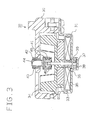
- This brushless motor has a motor housing 32 formed by an upper case 30 and a lower case 31 made of a magnetic material as illustrated in Fig. 3.
- a rotor 34 is provided in the housing 32.
- a pair of magnets 33 are symmetrically arranged about a drive shaft 36 at a position below the rotor 34.
- the magnets 33 are normally attracted by the lower case 31, therefore, when the rotor 34 is at rest, it is held at a stable position.
- Actuating coils 35 are arranged in the lower case 31 to face the magnets 33. To drive the motor, the actuating coils 35 are sequentially excited to rotate the rotor 34 and the drive shaft 36.
- a downward extending recess 37 is formed in the center of the lower case 31, and a resin plate 38 is set against the internal wall of the lower case 31.
- the lower end portion of the drive shaft 36 is supported in the recess 37 by a radial bushing 39 that sits on the resin plate 38.
- a bore 42 is formed in the center of the upper case 30.
- An anchor nut 43 is press fit in the bore 42.
- An adjust bolt 44 is screwed into the anchor nut 43 and extends into the housing 32.
- the bolt's lower end is secured onto the upper surface of a box-shaped support case 40.
- the support case 40 has a thrust bushing 41 disposed therein.
- the thrust bushing 41 is configured to provide tiny clearances 45. Supported by the bushing 41 is the upper portion of the drive shaft 36 which is inserted from the bottom of the support case 40.
- a brushless motor includes a housing that accommodates a rotor and a drive shaft.
- a relatively rigid thrust receiving member faces a first end of the drive shaft with a predetermined gap therebetween.
- the thrust receiving member is positioned to be struck by the first end of the drive shaft when the drive shaft vibrates.
- An impact absorbing resilient member absorbs the impact of the drive shaft when the drive shaft strikes thrust receiving member.
- the housing includes a lower casing that includes a magnetic material.
- the rotor also carries a magnet thereon. The magnet and the magnetic material cooperate to bias the drive shaft away from the thrust receiving member to help keep the drive shaft separated from the thrust receiving member when the drive shaft does not vibrate.
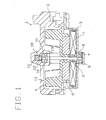
- a motor housing 1 for a fan motor provided in an inaccessible section of the vehicle, includes an upper case 2 made of a synthetic resin material and a lower case 3 made of a magnetic material.
- a rotor 4 is disposed in the housing 1.
- the rotor 4 has multiple circumferentially spaced magnets 5 embedded in the bottom thereof at equal intervals.
- a drive shaft 6 is secured to the center of the rotor 4.
- the lower end of the drive shaft 6 extends into a recess 7 that opens upward in the middle of the lower case 3.
- a resin plate 9 is set at the bottom of the recess 7 and a bushing 8 is set thereover.
- the bottom of the drive shaft 36 is rotatably supported by the bushing 8. When the motor rotates, the bushing 8 serves as a thrust and radial bearing.
- the rotor 4 and drive shaft 6 are normally held still by the attractive force acting between the magnets 5 and the lower case 3.
- Multiple solenoid coils 10 are arranged on the inner wall of the lower case 3 to face the magnets 5. When the actuating coils 10 are sequentially excited, a driving attractive force greater than the aforementioned attractive force is generated, thus rotating the rotor 4 and the drive shaft 6.
- Openings 11 are formed along the top surface of the uppercase 2 to provide air ducts.
- An upward extending projection in the center of the openings 11 forms an upwardly extending recess 12.
- the peripheral portion of the opening of the recess 12 projects downward to form a ring wall 13 having a larger diameter than the recess 12.
- the upper end of the drive shaft 6 is inserted in the ring wall 13.
- a bushing 15 is fitted against a shoulder 14 formed at the boundary between the recess 12 and the ring wall 13, and is held through a felt spacer 16 by a lock washer 17 in such a way that the bushing 15 will not come off in normal conditions.
- the bushing 15 rotatably supports the upper end of the drive shaft 6 and serves as a thrust bearing when the motor is driven.
- a resilient member 18 Fitted into the recess 12 is a resilient member 18, whose top has a plurality of cutaways to form clearances C to allow for deformation.
- Multiple support legs 19 protrude from the bottom surface of the resilient member 18, the bottom of each support leg 19 abutting on the bushing 15. The support legs 19, therefore, form a slight gap between the bottom of the resilient member 18 and the upper face of the bushing 15.
- a bore 20 is formed in the bottom of the resilient member 18.
- the top portion of the bore 20 is formed larger in diameter than the lower portion, thus providing a step 21.
- a thrust receiving plug 22 made of a hard synthetic resin material is pushed into the bore 20.
- the thrust receiver 22 has a large diameter head portion 23 at its upper end. The head is enlarged in the circumferential direction. The head 23 engages with the step 21 to keep the plug 22 from being removed from the bore 20.
- the plug 22 is designed so that its bottom end protrudes a little from the bore 20.
- the bottom of the plug 22 faces the top of the drive shaft 6 with a gap G therebetween.
Landscapes
- Engineering & Computer Science (AREA)
- Power Engineering (AREA)
- Motor Or Generator Frames (AREA)
- Brushless Motors (AREA)
Applications Claiming Priority (2)
| Application Number | Priority Date | Filing Date | Title |
|---|---|---|---|
| JP7310790U JPH0434847U (fr) | 1990-07-09 | 1990-07-09 | |
| JP73107/90U | 1990-07-09 |
Publications (2)
| Publication Number | Publication Date |
|---|---|
| EP0466402A2 true EP0466402A2 (fr) | 1992-01-15 |
| EP0466402A3 EP0466402A3 (en) | 1993-05-26 |
Family
ID=13508742
Family Applications (1)
| Application Number | Title | Priority Date | Filing Date |
|---|---|---|---|
| EP19910306092 Withdrawn EP0466402A3 (en) | 1990-07-09 | 1991-07-04 | Brushless motor |
Country Status (2)
| Country | Link |
|---|---|
| EP (1) | EP0466402A3 (fr) |
| JP (1) | JPH0434847U (fr) |
Cited By (4)
| Publication number | Priority date | Publication date | Assignee | Title |
|---|---|---|---|---|
| EP1120887A3 (fr) * | 2000-01-28 | 2002-08-21 | Matsushita Electric Industrial Co., Ltd. | Petit moteur plat et dispositif l'utilisant |
| US6664676B1 (en) | 1999-12-10 | 2003-12-16 | Matsushita Electric Industrial Co., Ltd. | Motor assembled by using motor-base-holder and method of assembling the same motor |
| FR2902170A1 (fr) * | 2006-06-09 | 2007-12-14 | Peugeot Citroen Automobiles Sa | Dispositif de commande pour boite de vitesses manuelle |
| CN101700930B (zh) * | 2009-10-21 | 2011-05-11 | 宁波市鄞州区绿州能源利用有限公司 | 垃圾渗沥液处理自动喷淋除泡装置 |
Family Cites Families (3)
| Publication number | Priority date | Publication date | Assignee | Title |
|---|---|---|---|---|
| DE7012895U (de) * | 1970-04-09 | 1970-09-10 | Siemens Ag | Im gehaeuse oder lagerschild eines kleinmotors angeordnetes spurlager. |
| DE2104452B2 (de) * | 1971-01-30 | 1981-03-12 | Siemens AG, 1000 Berlin und 8000 München | Anordnung zum Halten eines ein Wellenende aufnehmenden Wälzlagers, insbesondere Kugellagers |
| JPS61142941A (ja) * | 1984-12-13 | 1986-06-30 | Matsushita Electric Ind Co Ltd | モ−タ |
-
1990
- 1990-07-09 JP JP7310790U patent/JPH0434847U/ja active Pending
-
1991
- 1991-07-04 EP EP19910306092 patent/EP0466402A3/en not_active Withdrawn
Cited By (5)
| Publication number | Priority date | Publication date | Assignee | Title |
|---|---|---|---|---|
| US6664676B1 (en) | 1999-12-10 | 2003-12-16 | Matsushita Electric Industrial Co., Ltd. | Motor assembled by using motor-base-holder and method of assembling the same motor |
| EP1120887A3 (fr) * | 2000-01-28 | 2002-08-21 | Matsushita Electric Industrial Co., Ltd. | Petit moteur plat et dispositif l'utilisant |
| US6628028B2 (en) | 2000-01-28 | 2003-09-30 | Matsushita Electric Industrial Co., Ltd. | Small and flat vibrational motor having impact-resistant structure |
| FR2902170A1 (fr) * | 2006-06-09 | 2007-12-14 | Peugeot Citroen Automobiles Sa | Dispositif de commande pour boite de vitesses manuelle |
| CN101700930B (zh) * | 2009-10-21 | 2011-05-11 | 宁波市鄞州区绿州能源利用有限公司 | 垃圾渗沥液处理自动喷淋除泡装置 |
Also Published As
| Publication number | Publication date |
|---|---|
| JPH0434847U (fr) | 1992-03-24 |
| EP0466402A3 (en) | 1993-05-26 |
Similar Documents
| Publication | Publication Date | Title |
|---|---|---|
| US5204567A (en) | Brushless motor with resilient shaft end-play absorber | |
| US4943748A (en) | Motor with cup-shaped rotor having cylindrical portions of different diameter | |
| US4851731A (en) | Structure of a flat-type brushless DC motor | |
| US20050184609A1 (en) | Motor and magnetic bearing assembly thereof | |
| US20050035670A1 (en) | Motor | |
| JP2000217302A (ja) | モ―タ | |
| US5517374A (en) | Magnetic disk drive apparatus having disk clamp attachable using a single fastener | |
| EP0466402A2 (fr) | Moteur sans balais | |
| KR100234568B1 (ko) | 최전축의 반경방향 및 축방향 움직임을 제거하기 위한장치 | |
| KR100473492B1 (ko) | 광디스크 드라이버용 스핀들 모터 | |
| JP2004007905A (ja) | スピンドルモータ | |
| JPH1132460A (ja) | ブラシレスモータ | |
| KR200232132Y1 (ko) | 자기베어링이 있는 모터 | |
| JP2002130419A (ja) | アクチュエータ | |
| JP2596528Y2 (ja) | モータの空気ベアリングによるロータ支持構造及び回転軸支持構造 | |
| JP3709074B2 (ja) | ステッピングモータ | |
| KR100335235B1 (ko) | 디스크구동용스핀들모터 | |
| JP3048834B2 (ja) | 小型モータの取り付け構造 | |
| KR100557632B1 (ko) | 스핀들 모터 | |
| KR200150999Y1 (ko) | 압축기용 클러치 | |
| JPH05168183A (ja) | モータの防振装置 | |
| JP3659612B2 (ja) | バランス補正装置及びこれを備えた回転装置 | |
| US20010019233A1 (en) | Lateral pressure mechanism for driving shaft of motor | |
| JPH09103043A (ja) | スリーブ軸受を備えたモータ | |
| KR100269109B1 (ko) | 디스크 플레이어의 스핀들 모터 조립체 |
Legal Events
| Date | Code | Title | Description |
|---|---|---|---|
| PUAI | Public reference made under article 153(3) epc to a published international application that has entered the european phase |
Free format text: ORIGINAL CODE: 0009012 |
|
| AK | Designated contracting states |
Kind code of ref document: A2 Designated state(s): DE GB |
|
| PUAL | Search report despatched |
Free format text: ORIGINAL CODE: 0009013 |
|
| AK | Designated contracting states |
Kind code of ref document: A3 Designated state(s): DE GB |
|
| 18W | Application withdrawn |
Withdrawal date: 19930709 |
|
| STAA | Information on the status of an ep patent application or granted ep patent |
Free format text: STATUS: THE APPLICATION HAS BEEN WITHDRAWN |
|
| R18W | Application withdrawn (corrected) |
Effective date: 19930709 |