EP0466477A2 - Verfahren und Vorrichtung zur Erzeugung kurzlebiger optischer Elemente und Schaltungen - Google Patents
Verfahren und Vorrichtung zur Erzeugung kurzlebiger optischer Elemente und Schaltungen Download PDFInfo
- Publication number
- EP0466477A2 EP0466477A2 EP91306259A EP91306259A EP0466477A2 EP 0466477 A2 EP0466477 A2 EP 0466477A2 EP 91306259 A EP91306259 A EP 91306259A EP 91306259 A EP91306259 A EP 91306259A EP 0466477 A2 EP0466477 A2 EP 0466477A2
- Authority
- EP
- European Patent Office
- Prior art keywords
- light
- pulse
- linear material
- optical element
- transient optical
- Prior art date
- Legal status (The legal status is an assumption and is not a legal conclusion. Google has not performed a legal analysis and makes no representation as to the accuracy of the status listed.)
- Withdrawn
Links
Images



Classifications
-
- G—PHYSICS
- G02—OPTICS
- G02F—OPTICAL DEVICES OR ARRANGEMENTS FOR THE CONTROL OF LIGHT BY MODIFICATION OF THE OPTICAL PROPERTIES OF THE MEDIA OF THE ELEMENTS INVOLVED THEREIN; NON-LINEAR OPTICS; FREQUENCY-CHANGING OF LIGHT; OPTICAL LOGIC ELEMENTS; OPTICAL ANALOGUE/DIGITAL CONVERTERS
- G02F1/00—Devices or arrangements for the control of the intensity, colour, phase, polarisation or direction of light arriving from an independent light source, e.g. switching, gating or modulating; Non-linear optics
- G02F1/35—Non-linear optics
- G02F1/3515—All-optical modulation, gating, switching, e.g. control of a light beam by another light beam
-
- G—PHYSICS
- G02—OPTICS
- G02F—OPTICAL DEVICES OR ARRANGEMENTS FOR THE CONTROL OF LIGHT BY MODIFICATION OF THE OPTICAL PROPERTIES OF THE MEDIA OF THE ELEMENTS INVOLVED THEREIN; NON-LINEAR OPTICS; FREQUENCY-CHANGING OF LIGHT; OPTICAL LOGIC ELEMENTS; OPTICAL ANALOGUE/DIGITAL CONVERTERS
- G02F1/00—Devices or arrangements for the control of the intensity, colour, phase, polarisation or direction of light arriving from an independent light source, e.g. switching, gating or modulating; Non-linear optics
- G02F1/35—Non-linear optics
- G02F1/3511—Self-focusing or self-trapping of light; Light-induced birefringence; Induced optical Kerr-effect
Definitions
- the present invention relates generally to optical elements and circuits and more particularly to a method and apparatus for creating transient optical elements and circuits.
- Optical processing has been suggested for ultrafast speed and ultralarge bandwidth signal processing and computation systems. Based on the fast switching, parallel and free-space interconnect capabilities of optics, research has been conducted to implement various types of optical switches and modulators.
- An important class of optical modulators is the so-called optical beam deflector which employs a combination of optical switching and interconnection.
- Various acousto-optic and electro-optic type of deflectors have been developed. Because of their hybrid signal format, however, their deflection speed is limited to the nanosecond range. It has been suggested that in order to achieve higher processing speed, all-optical deflection schemes must be utilized. All optical deflection techniques are known.
- One aspect of this invention provides a new and improved apparatus for creating transient optical elements.
- Another aspect of this invention provides a new and improved method of creating transient optical elements.
- Still another aspect of this invention provides a new and improved method of creating transient optical circuits.
- Yet still another aspect of this invention provides a new and improved apparatus for creating transient optical circuits.
- a further aspect of this invention provides a method and apparatus for creating all-optical beam deflectors.
- Still a further aspect of this invention provides a method and apparatus for creating all-optical beam modulators.
- Yet still a further aspect of this invention provides a new and improved method and apparatus for creating ultrafast transient optical elements and circuits.
- a method of creating a transient optical element comprises providing a body of a nonlinear material and then passing a pulse of light through the body of nonlinear material, the pulse of light having a cross-sectional area corresponding to the cross-sectional area of the transient optical element to be created, the pulse of light having power sufficient to induce an index of refraction change over the portion of the body of nonlinear material through which it passes, the portion of the body of nonlinear material having the induced index of refraction change constituting the transient optical element and the duration of the transient optical element depending on the response time of the nonlinear material and the duration of the pulse of light.
- An apparatus for creating a transient optical element comprises a body of a nonlinear material and means for illuminating the body of nonlinear material with a pulse of light, the pulse of light having a cross-sectional area corresponding to the cross-sectional area of the transient optical element to be created, the pulse of light having power sufficient to induce an index of refraction change over the portion of the body of nonlinear material through which it passes, the portion of the body of nonlinear material having the induced index of refraction change constituting the transient optical element and the duration of the transient optical element depending on the response time of the nonlinear material and the duration of the pulse of light.
- the change in index of refraction in the body of non-linear material may be produced as a result of absorption (i.e. t from optical heating) and/or from the third order non-linear susceptability (N2 KERR effect).
- Transient optical circuits can be produced by creating a plurality of transient optical elements in accordance with the above aspect of this invention.
- Transient optical elements that may be created according to an aspect of this invention include prisms, lenses, gratings, beamsplitters, mirrors, waveguides and combinations of these elements.
- the present invention is directed to the concept of creating a transient optical element by passing a pulse of light through a body of nonlinear material, with the pulse of light having sufficient power to induce a change in the index of refraction in the body of nonlinear material over that portion in the body of nonlinear material through which the pulse of light passes, the cross-sectional area of the pulse of light determining the type of transient optical element that is created.
- the pulse of light may be shaped, for example, so as to create a prism inside the nonlinear medium that will deflect a signal beam or so as to create a lens to focus a signal beam.
- the invention may be used in such applications as optical signal processing, optical signal modulation, spatial light modulation, resolving points or images and optical signal computation.
- the change in index of refraction in the body of non-linear material may be caused by heat distribution caused by absorbtion of light within the nonlinear material and/or by third order non-linear susceptability (N2 Kerr Effect).
- Fig. 1 there is shown a schematic illustrating a beam deflection system 10 according to this invention.
- a body of a third order type nonlinear material 11 a pump beam 13, a signal (or input) beam 15 and a mask 17.
- Body 11 serves as the medium in which transient optical element is created and may be any third order nonlinear material such as cadmium selenide, glass, polymeres or liquid crystals.
- Pump beam 13 is the beam of light used to create the transient optical element in body 11 and signal beam 15 is the light beam which is to be processed (i.e. modulated or deflected etc.) by the transient optical element.
- Pump beam 11 may be produced by a pulse light source such as a YAG laser, a semiconductor laser or a Q-switched laser.
- Mask 17 is the element used to modify the cross-sectional area of pump beam 13 so as to produce a transient optical element of a desired shape and comprises a plate 17-1 of nontransparent material having an opening 17-2 (or transparent area) through which lighht can pass. Beams 13 and 15 overlap inside body of nonlinear material 11 at right angles to each other. Beam 15 is assumed to be plane wave. Beam 13 is area-modulated by mask 17 before entering nonlinear material 11.
- Beam 13 is more intense than beam 15, the intensity of beam 15 being such that it induces a negligble change in index of refraction of body 11 so as it passes through and the intensity of beam 13 being such that it induces a change in index refraction of body 11 over the portion of body 11 through which it passes.
- Opening (or transparent area) 17-2 in mask 17 is in the shape of a triangle.
- This induced refractive index change causes an induced transient triangularly shaped prism to be formed in nonlinear material 11.
- input beam 15 as it passes through the induced prism will undergo a direction change because of the transient prism, that is, an induced transient deflection will occur.
- input beam 11 is shown in dotted line after it passes through nonlinear material 11 in the absence of the transient prism and in the presence of the transient prism by solid lines.
- the change in.index of refraction may be produced as a result of absorption of light from temperature change in the body of non-linear material and/or by third order non-linear susceptability (N2 Kerr effect).
- Fig. 1 To calculate the deflection angle, in the example shown in Fig. 1 consider the geometry in the schematic shown in Fig. 2.
- the apex angle of the isosceles triangle is ⁇ .
- the deflection angle is ⁇ .
- the refractive indices of the modulated and unmodulated area are n ⁇ and n. respectively.
- the use of Snell's law show relation.
- Eq. (2) can be simplified by letting sin y and y for a small y. This approximation leads to ⁇ ⁇ L ⁇ n D where L and D are the triangle's base and height, respectively.
- a trianglular prism shaped deflector In addition to the triangularly shaped pump beam as shown in Fig.1. for producing a trianglular prism shaped deflector other shapes,such as circular, elliptical and rectangular can be used to obtain beam focusing, defocusing, diffraction, as well as phase-front control and aberration correction. Also a stepped shape beam can be used to create a grating and rectangular shapes used to redirect or split a signal beam.
- Fig. 3 an induced, area-modulated beam focusing scheme is shown.
- the pump beam (not shown) is area modulated using a mask having an elliptical shaped opening (not shown) so as to create lens with the front and back rail of R1 and R2.
- the simultaneous arrival of the (input) S beam will produce a one dimensional quadratic phase change.
- the output of S is where d is the separation between two spherical surfaces along the propagation direction. It can be shown that depending on R1 and R2 S(x,y) can either converge or diverge, i.e. undergoing an induced lensing effect.
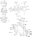
- FIG. 4 there is shown an optical system constructed according to the teachings of this invention and identified by reference numeral 20.
- a light pulse from a source 21 is passed through a spatial filter 22 which serves to make its intensity uniform in cross section.
- Light pulse is then split into two parts 23 and 25 by a beamsplitter 27, part 23 constituting a signal (or input) beam and part 25 constituting a pump beam.
- a beam expander 26 may be included to expand beam 25.
- Beamsplitter 27 is designed so that the intensity of part 23 is much less than the intensity of part 25. For example, the intensiity of part 23 may be 10% that of part 25.
- Part 23 is directed by mirrors 29 and 31 through body 33 of nonlinear material.
- Part 25 is passed through a mask 35 which modulates its cross-sectional area, through optics 37 and then passes through body 33 intersecting with pulse part 23 at right angles thereto.
- Optics 37 serves to sharpen the light pulse passing through mask 35 and brings the light pulse to focus inside nonlinear medium.
- Part 25 induces an index change in body 29 over the portion of body 33 through which it passes, with the portion of body 33 having the index change being shaped to define an optical element.
- the duration of the optical element so produced is a convolution of intensity of pulse part 25 and the response time of the nonlinear material used for body 33.
- the shape of the transient optical element is defined by the shape of the opening 37 in mask 35.
- Mask 35 which is shown in plan view in fig. 4(a) has a triangularly shaped opening 36 as shown In Fig. 4(a) which will result in the creation of an induced triangularly shaped prism.
- Body 33 is a third order nonlinear material. Examples of such materials are cadmium selenide, glass, organic polymers and liquid crystals. Body 33 may be doped with an absorbing material so as to produce an index change as a result of temperature change from absorption rather than index change caused by third order nonlinear susceptability (N2 Kerr effect) or in addition thereto.
- N2 Kerr effect third order nonlinear susceptability
- Source 21 may be a pulse laser such as a mode locked YAG laser, a semiconductor laser or a Q switched laser.
- a delay unit 38 may be disposed along the path of beam port 25 to insure that the two beams intersect within the body of non-linear material.
- masks having openings other than the triangular shape shown in Fig. 4(a) can be employed.
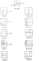
- the mask can have an elliptically shaped opening such as in mask 39 in Fig. 5 so as to induce (i.e. create) a transient lens, a stepped shape opening such as shown in mask 41 in Fig. 6 so as to induce a transient grating, a circular shaped opening such as shown by mask 43 in Fig. 7 to induce a transient spherical lens, a plurality of spaced rectangular openings such as shown in mask 45 in Fig. 8 to induce a transient beamsplitter or a transient mirror or a plurality of openings arranged in various ways such as, as examples, shown in Figs. 9-14 so as to induce different types transient optical circuits.
- Figs. 15-17 show how input beams are processed as they pass through the non-linear medium having optical circuits created using the masks of Figs. 12-14.
- Fig. 18 there is shown a modification of the system shown in Fig. 4, the modified system being identified by reference numeral 47.
- System 47 as shown in Fig. 18 differs from system 20 shown in Fig. 4 in that the pump and input beams 49 and 50, respectively are produced from separate sources 51 and 52 rather from a single source 21.
- the intensity of beam 50 is much lens than that of beam 49.
- a spatial filter 53 and optics 54 are disposed along the path of beam 49.
- Fig. 19 shown in perspective view a system according to this invention which includes two orthogonal pump pulses which interact in a nonlinear medium, the system being identified by reference numeral 55.
- a first pulse of light 56 from a source 57, such as a YAG laser is passed through a spatial filter 59 for making its intensity uniform and a mask 61 having an elliptically shaped opening and optics 63 and then passes through nonlinear medium 65, optics 63 serving to sharpen the pulse and bring it to focus in nonlinear medium 65.
- a source 57 such as a YAG laser
- a spatial filter 59 for making its intensity uniform
- a mask 61 having an elliptically shaped opening and optics 63 and then passes through nonlinear medium 65, optics 63 serving to sharpen the pulse and bring it to focus in nonlinear medium 65.
- a second pulse of light 66 from a source 67, which is identical to source 57 is passed through a spatial filter 68, a mask 69 and optics 71, which are identical to spatial filter 59, mask 61 and optics 63, respectively and then passes through nonlinear medium 65 intersecting the first pulse of light at right angles thereto.
- Each one of the two pulses has sufficient power to induce a change in the index of refraction in nonlinear medium 65.
- the combined action of the two pump pulses 56 and 66 induces a spherical lens in nonlinear medium 65.
- An input pulse 73 from source 75 on passing through nonlinear maximn 65 at right angles to the two pump pulses and during the time in which the induced lens is created will be focussed by the induced lens. Pulse 73 is sufficiently weak so that the index change it produces in nonlinear medium 65 is negligeable.
- FIG. 20 there is shown an embodiment of the invention identified by reference numeral 75 in which the pump and signal beams are coaxial.
- a pump pulse 77 from a source 79 is passed through a spatial filter 81, a mask 83 which may be for example triangularly shaped, focussing and sharpening optics 85 and then combined with an input pulse 87 from a source 89 by means of a beamsplitter 91 and is then directed through a nonlinear medium.
- FIG. 21 there is shown a 2-dimensional (2-d) spatial light modulator according to this invention.
- a set 97 of n vertically directed pump pulses labelled VP1, VP2, VP3, VP n , etc. and a set 99 of n horizontally directed pump pulses labelled HP1, HP2, HP3, HP n , etc. intersect in a nonlinear medium 101.
- a set of n2 input pulses labelled I1, I2, I3, I n also passes through nonlinear medium 101 with each one of the input pulses passing through the intersection of one of the vertically directed pump pulse 97 with one of the horizontally direct pump pulses 99.
- Each pump pulse is shaped in cross section to induce the formation of a focussing lens.
- the intersection of two pump pulses i.e. a horizontal pump pulse with a vertical pump pulse will induce a spherical lens that will focus its associated input pulse to a spot.
- the input pulse will be focussed as a line (i.e. one dimensionally).
Landscapes
- Physics & Mathematics (AREA)
- Nonlinear Science (AREA)
- General Physics & Mathematics (AREA)
- Optics & Photonics (AREA)
- Optical Modulation, Optical Deflection, Nonlinear Optics, Optical Demodulation, Optical Logic Elements (AREA)
Applications Claiming Priority (2)
| Application Number | Priority Date | Filing Date | Title |
|---|---|---|---|
| US552677 | 1990-07-11 | ||
| US07/552,677 US5126874A (en) | 1990-07-11 | 1990-07-11 | Method and apparatus for creating transient optical elements and circuits |
Publications (2)
| Publication Number | Publication Date |
|---|---|
| EP0466477A2 true EP0466477A2 (de) | 1992-01-15 |
| EP0466477A3 EP0466477A3 (en) | 1992-07-01 |
Family
ID=24206328
Family Applications (1)
| Application Number | Title | Priority Date | Filing Date |
|---|---|---|---|
| EP19910306259 Withdrawn EP0466477A3 (en) | 1990-07-11 | 1991-07-10 | Method and apparatus for creating transient optical elements and circuits |
Country Status (3)
| Country | Link |
|---|---|
| US (1) | US5126874A (de) |
| EP (1) | EP0466477A3 (de) |
| JP (1) | JPH06118459A (de) |
Cited By (5)
| Publication number | Priority date | Publication date | Assignee | Title |
|---|---|---|---|---|
| US5408480A (en) * | 1993-07-15 | 1995-04-18 | The United States Of America As Represented By The Administrator Of The National Aeronautics And Space Administration | Laser with optically driven Q-switch |
| EP0472345B1 (de) * | 1990-08-14 | 1996-04-17 | Hamamatsu Photonics K.K. | Optischer Verschluss für eine Kamera |
| EP0468794B1 (de) * | 1990-07-27 | 1996-04-17 | Hamamatsu Photonics K.K. | Optische Vorrichtung |
| EP0837357A3 (de) * | 1996-10-17 | 1999-03-17 | Ernst-August Stehr | Verfahren und Vorrichtung zum Modulieren von Licht |
| WO2003034141A3 (en) * | 2001-10-15 | 2004-01-22 | Boeing Co | Active optical system for beam-steering a laser beam |
Families Citing this family (12)
| Publication number | Priority date | Publication date | Assignee | Title |
|---|---|---|---|---|
| US5636050A (en) * | 1994-02-15 | 1997-06-03 | Research Foundation Of City College Of New York | Apparatus using optical deflection |
| US5406407A (en) * | 1994-03-04 | 1995-04-11 | Nec Research Institute Inc. | Third order room temperature nonlinear optical switches |
| US5838700A (en) * | 1995-07-28 | 1998-11-17 | Nauchny Tsentr Volokonnoi Optiki Pri Institute Obschei Fiziki Rossiiskoi Akademii Nauk | Raman fibre laser, bragg fibre-optical grating and method for changing the refraction index in germanium silicate glass |
| US5659415A (en) * | 1996-02-22 | 1997-08-19 | General Electric Company | Ultrafast optical modulator |
| US6449073B1 (en) | 1998-07-21 | 2002-09-10 | Corvis Corporation | Optical communication system |
| US7130540B2 (en) * | 1998-07-21 | 2006-10-31 | Corvis Corporation | Optical transmission systems, devices, and methods |
| US6771905B1 (en) | 1999-06-07 | 2004-08-03 | Corvis Corporation | Optical transmission systems including optical switching devices, control apparatuses, and methods |
| US6560005B2 (en) * | 2001-08-07 | 2003-05-06 | Tkd, Inc. | Acousto-optic devices |
| US6922529B2 (en) * | 2002-08-09 | 2005-07-26 | Corvis Corporation | Optical communications systems, devices, and methods |
| US20070292131A1 (en) * | 2006-06-15 | 2007-12-20 | Volodymyr Slobodyanyuk | Methodes and processes of all-optical switching of optical data packets |
| US9451177B2 (en) * | 2013-06-18 | 2016-09-20 | Massachusetts Institute Of Technology | Methods and apparatus for high speed camera |
| JP6487835B2 (ja) * | 2015-12-15 | 2019-03-20 | 日本電信電話株式会社 | 光偏向器およびその制御方法 |
Family Cites Families (7)
| Publication number | Priority date | Publication date | Assignee | Title |
|---|---|---|---|---|
| US3552824A (en) * | 1968-05-13 | 1971-01-05 | Rca Corp | Photochromic light valve |
| US3743423A (en) * | 1972-05-03 | 1973-07-03 | Westinghouse Electric Corp | Intensity spatial filter having uniformly spaced filter elements |
| US4496222A (en) * | 1981-12-21 | 1985-01-29 | Texas Instruments Incorporated | Apparatus and method for photolithography with phase conjugate optics |
| US4585301A (en) * | 1985-04-23 | 1986-04-29 | Utah State Universtiy Foundation | Optically actuated optical switch apparatus and methods |
| US4673250A (en) * | 1985-08-09 | 1987-06-16 | The United States Of America As Represented By The Secretary Of The Army | CO2 laser weapon countermeasure |
| US4921336A (en) * | 1985-12-20 | 1990-05-01 | Gte Laboratories Incorporated | Array of bistable devices and apparatus and methods for creating same |
| US4960322A (en) * | 1988-12-23 | 1990-10-02 | Rockwell International Corporation | Kerr-Bragg agile beam steering device |
-
1990
- 1990-07-11 US US07/552,677 patent/US5126874A/en not_active Expired - Lifetime
-
1991
- 1991-07-10 JP JP3170055A patent/JPH06118459A/ja active Pending
- 1991-07-10 EP EP19910306259 patent/EP0466477A3/en not_active Withdrawn
Cited By (6)
| Publication number | Priority date | Publication date | Assignee | Title |
|---|---|---|---|---|
| EP0468794B1 (de) * | 1990-07-27 | 1996-04-17 | Hamamatsu Photonics K.K. | Optische Vorrichtung |
| EP0472345B1 (de) * | 1990-08-14 | 1996-04-17 | Hamamatsu Photonics K.K. | Optischer Verschluss für eine Kamera |
| US5408480A (en) * | 1993-07-15 | 1995-04-18 | The United States Of America As Represented By The Administrator Of The National Aeronautics And Space Administration | Laser with optically driven Q-switch |
| EP0837357A3 (de) * | 1996-10-17 | 1999-03-17 | Ernst-August Stehr | Verfahren und Vorrichtung zum Modulieren von Licht |
| WO2003034141A3 (en) * | 2001-10-15 | 2004-01-22 | Boeing Co | Active optical system for beam-steering a laser beam |
| US6714568B2 (en) | 2001-10-15 | 2004-03-30 | The Boeing Company | Active optical system for beam-steering a laser beam |
Also Published As
| Publication number | Publication date |
|---|---|
| US5126874A (en) | 1992-06-30 |
| EP0466477A3 (en) | 1992-07-01 |
| JPH06118459A (ja) | 1994-04-28 |
Similar Documents
| Publication | Publication Date | Title |
|---|---|---|
| EP0466477A2 (de) | Verfahren und Vorrichtung zur Erzeugung kurzlebiger optischer Elemente und Schaltungen | |
| US6297894B1 (en) | Optical scheme for holographic imaging of complex diffractive elements in materials | |
| Hughes et al. | Theory of Z-scan measurements using Gaussian-Bessel beams | |
| Stoyanov et al. | Far-field pattern formation by manipulating the topological charges of square-shaped optical vortex lattices | |
| de La Fuente et al. | Spatial soliton-induced guiding by cross-phase modulation | |
| US4139277A (en) | Acousto-optic memory correlator | |
| GB1429221A (en) | Apparatus for providing an optical system using adaptive holo graphic components | |
| Torruellas et al. | Self-focusing and 2D spatial solitons in PTS | |
| Wallace et al. | Irradiance tailoring as a method of reducing thermal blooming in an absorbing medium | |
| Nolte et al. | Femtosecond writing of high-quality waveguides inside phosphate glasses and crystalline media using a bifocal approach | |
| US3612659A (en) | Passive beam-deflecting apparatus | |
| US5659415A (en) | Ultrafast optical modulator | |
| EP0468794B1 (de) | Optische Vorrichtung | |
| Sun et al. | Beam deflection with electro-optic polymeric waveguide prism array | |
| CA2281039C (en) | Novel optical scheme for holographic imaging of complex diffractive elements in materials | |
| JP3246677B2 (ja) | 光エコーメモリ記録再生装置及び方法 | |
| Said et al. | Nonlinearities in semiconductors for optical limiting | |
| SU1697041A1 (ru) | Устройство дл фокусировки гауссова пучка в пр моугольник с равномерным распределением интенсивности | |
| Park et al. | Photorefractive waveguide formation with refractive index reversal by use of thermal fixing | |
| RU1812544C (ru) | Способ адаптивного формировани изображени объекта, наход щегос за неровной границей раздела сред | |
| JP3962526B2 (ja) | 光記録方法 | |
| O'sullivan et al. | Focussing and defocussing regimes in the multistable optical response of single-crystal lead magnesium niobate | |
| Ng | Direct Laser Writing of Optical Waveguides in Transparent Materials Using a High Repetition Rate Femtosecond Laser | |
| Gabel | Degenerate four wave mixing in semiconductor doped glass waveguides | |
| Massey et al. | An electro‐optic technique for display and shaping of subnanosecond laser pulses |
Legal Events
| Date | Code | Title | Description |
|---|---|---|---|
| PUAI | Public reference made under article 153(3) epc to a published international application that has entered the european phase |
Free format text: ORIGINAL CODE: 0009012 |
|
| AK | Designated contracting states |
Kind code of ref document: A2 Designated state(s): DE FR GB |
|
| PUAL | Search report despatched |
Free format text: ORIGINAL CODE: 0009013 |
|
| AK | Designated contracting states |
Kind code of ref document: A3 Designated state(s): DE FR GB |
|
| 17P | Request for examination filed |
Effective date: 19921215 |
|
| 17Q | First examination report despatched |
Effective date: 19940808 |
|
| GRAG | Despatch of communication of intention to grant |
Free format text: ORIGINAL CODE: EPIDOS AGRA |
|
| GRAH | Despatch of communication of intention to grant a patent |
Free format text: ORIGINAL CODE: EPIDOS IGRA |
|
| STAA | Information on the status of an ep patent application or granted ep patent |
Free format text: STATUS: THE APPLICATION IS DEEMED TO BE WITHDRAWN |
|
| 18D | Application deemed to be withdrawn |
Effective date: 19960803 |