EP0466542A1 - Zylindergehäuse für eine Maschine mit Dampfabfuhr und Ölrückführleitungen - Google Patents
Zylindergehäuse für eine Maschine mit Dampfabfuhr und Ölrückführleitungen Download PDFInfo
- Publication number
- EP0466542A1 EP0466542A1 EP91401710A EP91401710A EP0466542A1 EP 0466542 A1 EP0466542 A1 EP 0466542A1 EP 91401710 A EP91401710 A EP 91401710A EP 91401710 A EP91401710 A EP 91401710A EP 0466542 A1 EP0466542 A1 EP 0466542A1
- Authority
- EP
- European Patent Office
- Prior art keywords
- casing
- conduits
- chamber
- circuit
- internal
- Prior art date
- Legal status (The legal status is an assumption and is not a legal conclusion. Google has not performed a legal analysis and makes no representation as to the accuracy of the status listed.)
- Granted
Links
- 238000004064 recycling Methods 0.000 title claims abstract description 18
- 239000007789 gas Substances 0.000 claims abstract description 21
- 239000010705 motor oil Substances 0.000 claims abstract description 8
- 238000002485 combustion reaction Methods 0.000 claims abstract description 6
- 239000003921 oil Substances 0.000 claims description 9
- 238000001816 cooling Methods 0.000 claims description 8
- 239000000110 cooling liquid Substances 0.000 claims description 2
- 238000000465 moulding Methods 0.000 description 4
- 239000002826 coolant Substances 0.000 description 3
- 238000007599 discharging Methods 0.000 description 2
- 238000010521 absorption reaction Methods 0.000 description 1
- 238000005266 casting Methods 0.000 description 1
- 239000000567 combustion gas Substances 0.000 description 1
- 239000000839 emulsion Substances 0.000 description 1
- 238000005461 lubrication Methods 0.000 description 1
- 238000003754 machining Methods 0.000 description 1
- 238000004519 manufacturing process Methods 0.000 description 1
- 238000002360 preparation method Methods 0.000 description 1
- 230000011218 segmentation Effects 0.000 description 1
- 238000000926 separation method Methods 0.000 description 1
Images


Classifications
-
- F—MECHANICAL ENGINEERING; LIGHTING; HEATING; WEAPONS; BLASTING
- F01—MACHINES OR ENGINES IN GENERAL; ENGINE PLANTS IN GENERAL; STEAM ENGINES
- F01M—LUBRICATING OF MACHINES OR ENGINES IN GENERAL; LUBRICATING INTERNAL COMBUSTION ENGINES; CRANKCASE VENTILATING
- F01M13/00—Crankcase ventilating or breathing
-
- F—MECHANICAL ENGINEERING; LIGHTING; HEATING; WEAPONS; BLASTING
- F02—COMBUSTION ENGINES; HOT-GAS OR COMBUSTION-PRODUCT ENGINE PLANTS
- F02B—INTERNAL-COMBUSTION PISTON ENGINES; COMBUSTION ENGINES IN GENERAL
- F02B75/00—Other engines
- F02B75/16—Engines characterised by number of cylinders, e.g. single-cylinder engines
- F02B75/18—Multi-cylinder engines
- F02B75/22—Multi-cylinder engines with cylinders in V, fan, or star arrangement
-
- F—MECHANICAL ENGINEERING; LIGHTING; HEATING; WEAPONS; BLASTING
- F02—COMBUSTION ENGINES; HOT-GAS OR COMBUSTION-PRODUCT ENGINE PLANTS
- F02F—CYLINDERS, PISTONS OR CASINGS, FOR COMBUSTION ENGINES; ARRANGEMENTS OF SEALINGS IN COMBUSTION ENGINES
- F02F7/00—Casings, e.g. crankcases
- F02F7/0002—Cylinder arrangements
- F02F7/0012—Crankcases of V-engines
-
- F—MECHANICAL ENGINEERING; LIGHTING; HEATING; WEAPONS; BLASTING
- F02—COMBUSTION ENGINES; HOT-GAS OR COMBUSTION-PRODUCT ENGINE PLANTS
- F02B—INTERNAL-COMBUSTION PISTON ENGINES; COMBUSTION ENGINES IN GENERAL
- F02B75/00—Other engines
- F02B75/16—Engines characterised by number of cylinders, e.g. single-cylinder engines
- F02B75/18—Multi-cylinder engines
- F02B2075/1804—Number of cylinders
- F02B2075/1824—Number of cylinders six
-
- F—MECHANICAL ENGINEERING; LIGHTING; HEATING; WEAPONS; BLASTING
- F02—COMBUSTION ENGINES; HOT-GAS OR COMBUSTION-PRODUCT ENGINE PLANTS
- F02F—CYLINDERS, PISTONS OR CASINGS, FOR COMBUSTION ENGINES; ARRANGEMENTS OF SEALINGS IN COMBUSTION ENGINES
- F02F1/00—Cylinders; Cylinder heads
- F02F1/02—Cylinders; Cylinder heads having cooling means
- F02F1/10—Cylinders; Cylinder heads having cooling means for liquid cooling
- F02F2001/104—Cylinders; Cylinder heads having cooling means for liquid cooling using an open deck, i.e. the water jacket is open at the block top face
-
- F—MECHANICAL ENGINEERING; LIGHTING; HEATING; WEAPONS; BLASTING
- F02—COMBUSTION ENGINES; HOT-GAS OR COMBUSTION-PRODUCT ENGINE PLANTS
- F02F—CYLINDERS, PISTONS OR CASINGS, FOR COMBUSTION ENGINES; ARRANGEMENTS OF SEALINGS IN COMBUSTION ENGINES
- F02F2200/00—Manufacturing
- F02F2200/06—Casting
Definitions
- the present invention relates to an upper casing or cylinder block for any internal combustion engine, for example of the V-cylinder or in-line type.
- the internal conduits of the prior art are of complex shape, and have small gas and oil passage sections.
- these conduits are obtained by machining or with the aid of foundry pins or fragile molding cores, so that the casings thus produced are expensive and insufficiently rigid.
- the object of the present invention is to remedy these drawbacks by proposing an upper casing with internal ducts for discharging the gases from the casing and for recycling the engine oil which are of simple shape. and large passage sections, and which, moreover, can be produced at a lower cost, while increasing the rigidity of the casing, thanks to the use of a unique and resistant molding core.
- the subject of the invention is an upper cylinder head casing for any internal combustion engine, such as of the V-cylinder or in-line type, and comprising internal conduits which connect the upper part of the casing to compartments separating the crankshaft bearings, these conduits allowing the evacuation of gases from the crankcase and the recycling of engine oil, this crankcase being characterized in that said internal evacuation and recycling conduits open into a flattened chamber, arranged near the lower compartments and crossed perpendicularly by the cylinders, said chamber and said internal conduits forming a circuit from the foundry.
- the invention is further characterized in that the circuit includes gas passages from the casing which connect the aforementioned chamber to each of the lower compartments.
- the upper casing is further characterized in that internal oil recycling conduits extend substantially parallel to the cylinders and respectively connect the circuit chamber to a mounting plane of a cylinder head and to an opposite lower face of the casing, these conduits being offset from each other.
- the circuit chamber has the shape of a dihedral, with a central or edge part which is connected to conduits internal extending between the two lines of cylinders and opening onto a face of the casing provided for mounting a gas treatment member of the casing.
- the invention is further characterized in that cooling chambers are formed around the cylinders for the circulation of a cooling liquid, the circuit chamber being located between the cooling chambers and the aforementioned lower compartments.
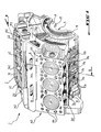
- Figure 1 is a perspective view of an upper casing according to the invention, for an internal combustion engine of the V-cylinder type.
- Figure 2 is a sectional view of the upper housing of Figure 1 and along the line II-II.
- FIG. 3 illustrates in perspective the shape of the chamber and of the internal conduits which constitute the evacuation and recycling circuit according to the invention.
- an engine M notably comprises an upper casing or cylinder block 1, a lower casing 2 and two cylinder heads 3a and 3b which are fixed to the upper cylinder head casing 1 .
- the engine M is of the type with 6 cylinders in V, that is to say comprises, on either side of a longitudinal plane XX ′ two lines of three cylinders 41 and 42. It is also noted that lower compartments 5 which separate transverse walls 11 (only one of which is visible in FIG. 1 and on FIG. 2) in which crankshaft bearings 12 are formed are produced in the upper casing 1 so as to open into a face forming a lower joint plane 13 against which the lower casing 2 is mounted.
- Each cylinder 41, 42 opens on the one hand into the upper part 143 of the casing 1 and on the other hand into one of the lower compartments 5.
- the three aligned cylinders which are designated by the reference numeral 41 are produced on one side of the longitudinal plane XX ′ and open onto a joint plane 141 of the upper part 143, on which plane the cylinder head 3a is mounted.
- the other three cylinders 42 are produced in the casing 1 on the other side of the plane X-X ′ and lead to another joint plane 142 of the upper part 143, on which plane the cylinder head 3b is mounted.
- each cylinder 41, 42 can be inserted into each cylinder 41, 42, for example during the molding of the upper casing 1.
- coolant supply conduits produced in the casing 1 and which extend substantially parallel to a longitudinal direction of the casing 1.
- the supply conduits 151 and 152 are respectively connected to cooling chambers 161 and 162 which are formed around each cylinder 41, 42, so as to allow circulation of coolant in the casing 1.
- Holes 171, 172 for communication of the cooling chambers 161 and 162 with the cylinder heads 3a and 3b open respectively in the joint planes 141 and 142.
- the coolant is introduced into the casing 1 via an opening 153 which opens into a transverse face 6 of the casing 1 and which extends substantially parallel to the transverse walls described above.
- FIG. 2 shows a longitudinal channel 173 for circulation of pressurized oil which extends in the longitudinal direction of the casing 2, along the lower compartments 5.
- the upper casing 1 also comprises internal conduits for discharging gas from the casing and for recycling the oil which will now be described, with further reference to FIG. 3.
- the upper casing 1 comprises internal pipes 7 for recycling engine oil and internal pipes 8 for evacuating the gases from the casing which open into a chamber 9, so as to form a circuit C coming from foundry with the casing 1 and shown in perspective in FIG. 3.
- the chamber 9 of the circuit C is in the form of a flattened dihedron and extends near a top wall 51 of the lower compartments 5 of the casing 1.
- the chamber 9 is therefore constituted by two flattened and contiguous parts identified at 91 and 92 Each flattened part 91 and 92 of the chamber 9 is crossed substantially at right angles by the cylinders 41 and 42, respectively.
- a central part 93 of the chamber 9 forms an edge which extends in the longitudinal direction of the casing 1, right through the chamber 9.
- Two evacuation conduits 8 of oblong section extend, between the cylinders 41, 42, from the upper part of the edge 93 to a central face 144 of the casing 1 which is provided for mounting a treatment (not shown) of the crankcase gases.
- the chamber 9 of the circuit C formed in the upper casing 1 is located between the cooling chambers 161 and 162 and the lower compartments 5.
- the recycling conduits 7 extend laterally from each free end of the flattened parts 91, 92 of the chamber 9, and consist of upper sections 7a and lower sections 7b.
- each flattened part 91, 92 of the chamber 9 comprises five upper sections 7a and three lower sections 7b, of oblong section.
- the upper sections 7a of the recycling conduits 7 are formed in the casing 1 so as to extend substantially parallel to the cylinder lines 41 and 42.
- These upper sections 7a are connected five to five, at their upper part, by channels 71 and 72 which open respectively in the joint planes 141 and 142.
- each of the channels 71 and 72 is produced near a lateral flange 241, 242 of the joint planes 141 and 142 of the housing 1, and extend in a direction substantially parallel to the longitudinal direction of the housing.
- the lower sections 7b of the recycling conduits 7 extend, from top to bottom along the side walls 52 of the compartments 5 which are parallel to the plane XX ′, from one of the flattened parts 91, 92 of the chamber 9 to the joint plane 13 against which the lower casing 2 is mounted.
- the upper sections 7a and the lower sections 7b of the recycling conduits 7 are offset from one another.
- the lower sections 7b are substantially parallel to the plane X-X ′ and therefore do not extend exactly in alignment with the upper sections 7a which are parallel to the cylinders 41, 42.
- the lower sections 7b open into the chamber 9 at locations which are not located exactly opposite the ends of the upper sections 7a which open into each flattened part 91, 92 of the chamber 9.
- Such a shift between the sections 7a and 7b makes it possible to "break" the flow of oil flow towards the lower casing 2, but also makes it possible to improve the evacuation of the gases by allowing the gases trapped in the oil from the lower sump 2 to escape through the lower sections 7b.
- passages 94 which pass through the wall 51 to open into each compartment 5, so as to allow optimal evacuation of the gases from the casing using the conduits 8, and for example to a device for treating these gases. It is possible, thanks to such passages 94, to connect the various crankshaft mounting compartments 5, in order to improve the operation of the engine.
- an upper cylinder head casing of inexpensive production in which it is easy to produce gas evacuation and oil recycling conduits by interposing a one-piece molding core and of similar shape to the circuit visible in Figure 3 in the casting mold of the housing.
- a monobloc core is arranged during the preparation of the mold between the cores making it possible to obtain the cooling chambers and the cores defining the mounting compartments of the crankshaft.
- the upper casing according to the invention has the advantage of being more rigid thanks to the different separation walls of the chambers and the conduits, which also has the result of improving the sound absorption of the casing.
- circuit C described above and provided for an engine M of the V-cylinder type can also be adapted to an engine of the in-line cylinder type, and that the number of conduits as well as the section of those -these can be adapted to the desired engine operating characteristics.
Landscapes
- Engineering & Computer Science (AREA)
- Mechanical Engineering (AREA)
- General Engineering & Computer Science (AREA)
- Chemical & Material Sciences (AREA)
- Combustion & Propulsion (AREA)
- Lubrication Details And Ventilation Of Internal Combustion Engines (AREA)
- Cylinder Crankcases Of Internal Combustion Engines (AREA)
- Lubrication Of Internal Combustion Engines (AREA)
Applications Claiming Priority (2)
| Application Number | Priority Date | Filing Date | Title |
|---|---|---|---|
| FR9008844A FR2664654B1 (fr) | 1990-07-11 | 1990-07-11 | Carter cylindres de moteur avec circuit d'evacuation des gaz du carter et de recyclage d'huile. |
| FR9008844 | 1990-07-11 |
Publications (2)
| Publication Number | Publication Date |
|---|---|
| EP0466542A1 true EP0466542A1 (de) | 1992-01-15 |
| EP0466542B1 EP0466542B1 (de) | 1993-05-26 |
Family
ID=9398610
Family Applications (1)
| Application Number | Title | Priority Date | Filing Date |
|---|---|---|---|
| EP91401710A Expired - Lifetime EP0466542B1 (de) | 1990-07-11 | 1991-06-25 | Zylindergehäuse für eine Maschine mit Dampfabfuhr und Ölrückführleitungen |
Country Status (5)
| Country | Link |
|---|---|
| US (1) | US5115791A (de) |
| EP (1) | EP0466542B1 (de) |
| JP (1) | JP3229340B2 (de) |
| DE (1) | DE69100092T2 (de) |
| FR (1) | FR2664654B1 (de) |
Cited By (3)
| Publication number | Priority date | Publication date | Assignee | Title |
|---|---|---|---|---|
| EP1283346A3 (de) * | 2001-08-08 | 2003-08-13 | Bayerische Motoren Werke Aktiengesellschaft | Kurbelgehäuse für eine Brennkraftmaschine, insbesondere mit zueinander geneigt angeordneten Zylinderreihen, vor allem V-Motor |
| WO2007074384A3 (en) * | 2005-12-28 | 2008-01-03 | Toyota Motor Co Ltd | Pcv system for v-type engine |
| DE102018002554A1 (de) * | 2017-12-22 | 2019-06-27 | Deutz Aktiengesellschaft | Zylinderkurbelgehäuse mit Schürzen-Leiterstruktur |
Families Citing this family (13)
| Publication number | Priority date | Publication date | Assignee | Title |
|---|---|---|---|---|
| DE4231284A1 (de) * | 1992-09-18 | 1994-03-24 | Bruehl Eisenwerk | Zylinderblock für eine Brennkraftmaschine |
| DE19608066C1 (de) * | 1996-03-02 | 1997-06-05 | Daimler Benz Ag | Kurbelraumentlüftung für eine Brennkraftmaschine |
| US6123061A (en) * | 1997-02-25 | 2000-09-26 | Cummins Engine Company, Inc. | Crankcase ventilation system |
| DE19809411A1 (de) * | 1998-03-05 | 1999-09-16 | Volkswagen Ag | Brennkraftmaschine |
| DE19855562C1 (de) * | 1998-12-02 | 2000-05-31 | Mtu Friedrichshafen Gmbh | Kurbelgehäuse |
| US6067952A (en) * | 1998-12-10 | 2000-05-30 | Brunswick Corporation | Cylinder bore lubrication with residual oil |
| JP3867837B2 (ja) * | 2000-12-20 | 2007-01-17 | 本田技研工業株式会社 | 内燃機関 |
| US6702908B1 (en) * | 2002-01-16 | 2004-03-09 | Hamilton Sundstrand Corporation | Method of making a cylinder block with unlined piston bores |
| US7258097B1 (en) * | 2006-08-08 | 2007-08-21 | International Engine Intellectual Property Company, Llc | Crankcase for an internal combustion engine |
| DE102009016444B4 (de) | 2009-04-04 | 2022-03-03 | Daimler Ag | Zylinderkurbelgehäuse und Verfahren zu dessen Herstellung |
| US8464696B2 (en) * | 2010-05-17 | 2013-06-18 | Ford Global Technologies, Llc | Supercharged engine system |
| CN103511113B (zh) * | 2013-10-08 | 2018-07-17 | 潍柴动力股份有限公司 | 一种发动机及其机体 |
| FR3023591B1 (fr) * | 2014-07-11 | 2019-04-26 | Renault S.A.S. | " moteur a combustion interne comportant un bloc-moteur muni d'un deflecteur d'huile " |
Citations (3)
| Publication number | Priority date | Publication date | Assignee | Title |
|---|---|---|---|---|
| US1916522A (en) * | 1930-01-04 | 1933-07-04 | Gen Motors Corp | V-8 engine |
| FR2065069A5 (de) * | 1969-12-22 | 1971-07-23 | Kloeckner Humboldt Deutz Ag | |
| FR2223562A1 (de) * | 1973-03-27 | 1974-10-25 | American Challenger Corp |
Family Cites Families (5)
| Publication number | Priority date | Publication date | Assignee | Title |
|---|---|---|---|---|
| US3949719A (en) * | 1975-01-27 | 1976-04-13 | Kar Products Inc. | Volumetric control valve unit for crankcase ventilation system |
| JPS59100910U (ja) * | 1982-12-24 | 1984-07-07 | 本田技研工業株式会社 | V型内燃機関用ブロ−バイガス還元装置 |
| US4541399A (en) * | 1983-03-03 | 1985-09-17 | Mazda Motor Corporation | Breather arrangement for internal combustion engine |
| US4603673A (en) * | 1984-03-03 | 1986-08-05 | Mazda Motor Corporation | Breather device in internal combustion engine |
| JP2678294B2 (ja) * | 1988-09-13 | 1997-11-17 | マツダ株式会社 | V型エンジンのブローバイガス還流装置 |
-
1990
- 1990-07-11 FR FR9008844A patent/FR2664654B1/fr not_active Expired - Lifetime
-
1991
- 1991-06-25 EP EP91401710A patent/EP0466542B1/de not_active Expired - Lifetime
- 1991-06-25 DE DE91401710T patent/DE69100092T2/de not_active Expired - Fee Related
- 1991-07-10 JP JP16970491A patent/JP3229340B2/ja not_active Expired - Fee Related
- 1991-07-11 US US07/728,706 patent/US5115791A/en not_active Expired - Lifetime
Patent Citations (3)
| Publication number | Priority date | Publication date | Assignee | Title |
|---|---|---|---|---|
| US1916522A (en) * | 1930-01-04 | 1933-07-04 | Gen Motors Corp | V-8 engine |
| FR2065069A5 (de) * | 1969-12-22 | 1971-07-23 | Kloeckner Humboldt Deutz Ag | |
| FR2223562A1 (de) * | 1973-03-27 | 1974-10-25 | American Challenger Corp |
Cited By (4)
| Publication number | Priority date | Publication date | Assignee | Title |
|---|---|---|---|---|
| EP1283346A3 (de) * | 2001-08-08 | 2003-08-13 | Bayerische Motoren Werke Aktiengesellschaft | Kurbelgehäuse für eine Brennkraftmaschine, insbesondere mit zueinander geneigt angeordneten Zylinderreihen, vor allem V-Motor |
| WO2007074384A3 (en) * | 2005-12-28 | 2008-01-03 | Toyota Motor Co Ltd | Pcv system for v-type engine |
| US8061336B2 (en) | 2005-12-28 | 2011-11-22 | Toyota Jidosha Kabushiki Kaisha | PCV system for V-type engine |
| DE102018002554A1 (de) * | 2017-12-22 | 2019-06-27 | Deutz Aktiengesellschaft | Zylinderkurbelgehäuse mit Schürzen-Leiterstruktur |
Also Published As
| Publication number | Publication date |
|---|---|
| EP0466542B1 (de) | 1993-05-26 |
| DE69100092D1 (de) | 1993-07-01 |
| JP3229340B2 (ja) | 2001-11-19 |
| FR2664654A1 (fr) | 1992-01-17 |
| DE69100092T2 (de) | 1993-11-04 |
| FR2664654B1 (fr) | 1992-11-06 |
| US5115791A (en) | 1992-05-26 |
| JPH0586976A (ja) | 1993-04-06 |
Similar Documents
| Publication | Publication Date | Title |
|---|---|---|
| EP0466542B1 (de) | Zylindergehäuse für eine Maschine mit Dampfabfuhr und Ölrückführleitungen | |
| CN103775233B (zh) | 气缸盖的水套结构 | |
| FR2607553A1 (fr) | Dispositif de support pour deux arbres a cames dans la culasse d'un moteur a plusieurs cylindres en ligne | |
| FR2574128A1 (fr) | Reniflard de moteur a combustion interne | |
| FR2464364A1 (fr) | Moteur a combustion interne | |
| EP0448431B1 (de) | Einlass- und Ölabscheidevorrichtung für eine Brennkraftmaschine und Maschine versehen mit dieser Vorrichtung | |
| EP2553253A1 (de) | Gasverteilerkanal im zylinderkopf eines motors, satz mit einem verteilerkanal und motorzylinderkopf | |
| BE1006901A3 (fr) | Moteur a combustion interne et son procede de fabrication. | |
| FR2745603A1 (fr) | Systeme de ventilation du compartiment du vilebrequin pour un moteur a combustion interne | |
| FR2751251A1 (fr) | Procede et noyau pour la realisation par moulage d'une culasse de moteur a combustion interne | |
| EP1859129B1 (de) | Ölzirkulationsvorrichtung für verbrennungsmotor | |
| FR2661455A1 (fr) | Dispositif de recuperation et de recyclage des gaz de combustion imbrules emanant du carter d'un moteur a combustion interne, et moteur equipe de ce dispositif. | |
| US10464627B2 (en) | Straddled vehicle | |
| FR2764335A1 (fr) | Culasse de cylindre pour un moteur a combustion interne, noyau de coulee d'huile dans une telle culasse | |
| FR2588366A1 (fr) | Dispositif de boite a eau et de vase d'expansion, et echangeur de chaleur comprenant ce dispositif | |
| FR2694788A1 (fr) | Conduit d'admission pour culasse de moteur à combustion interne et procédé de réalistion. | |
| EP1135587B1 (de) | Zylinderkopf für eine flüssigkeitsgekühlte brennkraftmaschine | |
| FR2973071A1 (fr) | Decanteur comportant un canal de refroidissement | |
| EP1959123A1 (de) | Verbrennungsmotor mit einem Verteiler für Ansaugluft und Herstellungsverfahren eines solchen Verteilers | |
| EP1227237B1 (de) | Zylinderkopf für eine Brennkraftmaschine mit einem Ventilierungskanal | |
| FR2557687A1 (fr) | Dispositif formant boite a eau et vase d'expansion pour un echangeur de chaleur, comprenant un passage de degazage de liquide | |
| EP1781434A2 (de) | Zylinderblock, formgebungsverfahren und motor mit einem derartigen zylinder | |
| FR3063466A1 (fr) | Ensemble comportant un cache-moteur | |
| FR3122916A1 (fr) | Bloc moteur avec déflecteur d'huile | |
| EP3492729A1 (de) | Zylinderkopf eines kraftfahrzeugs, der ein integriertes auspuffsammelrohr umfasst |
Legal Events
| Date | Code | Title | Description |
|---|---|---|---|
| PUAI | Public reference made under article 153(3) epc to a published international application that has entered the european phase |
Free format text: ORIGINAL CODE: 0009012 |
|
| AK | Designated contracting states |
Kind code of ref document: A1 Designated state(s): DE GB IT |
|
| 17P | Request for examination filed |
Effective date: 19920303 |
|
| 17Q | First examination report despatched |
Effective date: 19920908 |
|
| GRAA | (expected) grant |
Free format text: ORIGINAL CODE: 0009210 |
|
| AK | Designated contracting states |
Kind code of ref document: B1 Designated state(s): DE GB IT |
|
| REF | Corresponds to: |
Ref document number: 69100092 Country of ref document: DE Date of ref document: 19930701 |
|
| ITF | It: translation for a ep patent filed | ||
| GBT | Gb: translation of ep patent filed (gb section 77(6)(a)/1977) |
Effective date: 19930805 |
|
| PLBE | No opposition filed within time limit |
Free format text: ORIGINAL CODE: 0009261 |
|
| STAA | Information on the status of an ep patent application or granted ep patent |
Free format text: STATUS: NO OPPOSITION FILED WITHIN TIME LIMIT |
|
| 26N | No opposition filed | ||
| REG | Reference to a national code |
Ref country code: GB Ref legal event code: IF02 |
|
| PGFP | Annual fee paid to national office [announced via postgrant information from national office to epo] |
Ref country code: IT Payment date: 20080614 Year of fee payment: 18 |
|
| PGFP | Annual fee paid to national office [announced via postgrant information from national office to epo] |
Ref country code: DE Payment date: 20080617 Year of fee payment: 18 |
|
| PGFP | Annual fee paid to national office [announced via postgrant information from national office to epo] |
Ref country code: GB Payment date: 20080527 Year of fee payment: 18 |
|
| GBPC | Gb: european patent ceased through non-payment of renewal fee |
Effective date: 20090625 |
|
| PG25 | Lapsed in a contracting state [announced via postgrant information from national office to epo] |
Ref country code: GB Free format text: LAPSE BECAUSE OF NON-PAYMENT OF DUE FEES Effective date: 20090625 |
|
| PG25 | Lapsed in a contracting state [announced via postgrant information from national office to epo] |
Ref country code: DE Free format text: LAPSE BECAUSE OF NON-PAYMENT OF DUE FEES Effective date: 20100101 |
|
| PG25 | Lapsed in a contracting state [announced via postgrant information from national office to epo] |
Ref country code: IT Free format text: LAPSE BECAUSE OF NON-PAYMENT OF DUE FEES Effective date: 20090625 |