EP0466576B1 - Perfectionnements apportés aux chaudières mixtes de chauffage central - Google Patents
Perfectionnements apportés aux chaudières mixtes de chauffage central Download PDFInfo
- Publication number
- EP0466576B1 EP0466576B1 EP91401904A EP91401904A EP0466576B1 EP 0466576 B1 EP0466576 B1 EP 0466576B1 EP 91401904 A EP91401904 A EP 91401904A EP 91401904 A EP91401904 A EP 91401904A EP 0466576 B1 EP0466576 B1 EP 0466576B1
- Authority
- EP
- European Patent Office
- Prior art keywords
- module
- boiler
- duct
- circuit
- outlet
- Prior art date
- Legal status (The legal status is an assumption and is not a legal conclusion. Google has not performed a legal analysis and makes no representation as to the accuracy of the status listed.)
- Expired - Lifetime
Links
- 238000010438 heat treatment Methods 0.000 title claims abstract description 39
- XLYOFNOQVPJJNP-UHFFFAOYSA-N water Substances O XLYOFNOQVPJJNP-UHFFFAOYSA-N 0.000 claims abstract description 41
- 230000004888 barrier function Effects 0.000 claims description 7
- 239000004033 plastic Substances 0.000 claims description 7
- 229920003023 plastic Polymers 0.000 claims description 7
- 230000002093 peripheral effect Effects 0.000 claims description 4
- 239000012535 impurity Substances 0.000 claims description 3
- 239000000463 material Substances 0.000 abstract description 6
- 239000008236 heating water Substances 0.000 abstract description 5
- 239000002991 molded plastic Substances 0.000 abstract 1
- 235000021183 entrée Nutrition 0.000 description 12
- 238000002955 isolation Methods 0.000 description 9
- 238000009434 installation Methods 0.000 description 4
- 238000010276 construction Methods 0.000 description 3
- 229910052751 metal Inorganic materials 0.000 description 3
- 239000002184 metal Substances 0.000 description 3
- 239000004697 Polyetherimide Substances 0.000 description 2
- 238000009413 insulation Methods 0.000 description 2
- 229920001601 polyetherimide Polymers 0.000 description 2
- 229920012287 polyphenylene sulfone Polymers 0.000 description 2
- 229910000838 Al alloy Inorganic materials 0.000 description 1
- 208000031968 Cadaver Diseases 0.000 description 1
- 239000004695 Polyether sulfone Substances 0.000 description 1
- 241001080024 Telles Species 0.000 description 1
- 238000002485 combustion reaction Methods 0.000 description 1
- 230000000295 complement effect Effects 0.000 description 1
- 239000000470 constituent Substances 0.000 description 1
- 230000007797 corrosion Effects 0.000 description 1
- 238000005260 corrosion Methods 0.000 description 1
- 239000003822 epoxy resin Substances 0.000 description 1
- 238000005192 partition Methods 0.000 description 1
- 229920000647 polyepoxide Polymers 0.000 description 1
- 229920006393 polyether sulfone Polymers 0.000 description 1
Images


Classifications
-
- F—MECHANICAL ENGINEERING; LIGHTING; HEATING; WEAPONS; BLASTING
- F24—HEATING; RANGES; VENTILATING
- F24D—DOMESTIC- OR SPACE-HEATING SYSTEMS, e.g. CENTRAL HEATING SYSTEMS; DOMESTIC HOT-WATER SUPPLY SYSTEMS; ELEMENTS OR COMPONENTS THEREFOR
- F24D3/00—Hot-water central heating systems
-
- F—MECHANICAL ENGINEERING; LIGHTING; HEATING; WEAPONS; BLASTING
- F24—HEATING; RANGES; VENTILATING
- F24H—FLUID HEATERS, e.g. WATER OR AIR HEATERS, HAVING HEAT-GENERATING MEANS, e.g. HEAT PUMPS, IN GENERAL
- F24H9/00—Details
- F24H9/12—Arrangements for connecting heaters to circulation pipes
- F24H9/13—Arrangements for connecting heaters to circulation pipes for water heaters
-
- Y—GENERAL TAGGING OF NEW TECHNOLOGICAL DEVELOPMENTS; GENERAL TAGGING OF CROSS-SECTIONAL TECHNOLOGIES SPANNING OVER SEVERAL SECTIONS OF THE IPC; TECHNICAL SUBJECTS COVERED BY FORMER USPC CROSS-REFERENCE ART COLLECTIONS [XRACs] AND DIGESTS
- Y10—TECHNICAL SUBJECTS COVERED BY FORMER USPC
- Y10T—TECHNICAL SUBJECTS COVERED BY FORMER US CLASSIFICATION
- Y10T137/00—Fluid handling
- Y10T137/8158—With indicator, register, recorder, alarm or inspection means
- Y10T137/8326—Fluid pressure responsive indicator, recorder or alarm
-
- Y—GENERAL TAGGING OF NEW TECHNOLOGICAL DEVELOPMENTS; GENERAL TAGGING OF CROSS-SECTIONAL TECHNOLOGIES SPANNING OVER SEVERAL SECTIONS OF THE IPC; TECHNICAL SUBJECTS COVERED BY FORMER USPC CROSS-REFERENCE ART COLLECTIONS [XRACs] AND DIGESTS
- Y10—TECHNICAL SUBJECTS COVERED BY FORMER USPC
- Y10T—TECHNICAL SUBJECTS COVERED BY FORMER US CLASSIFICATION
- Y10T137/00—Fluid handling
- Y10T137/8593—Systems
- Y10T137/877—With flow control means for branched passages
- Y10T137/87885—Sectional block structure
Definitions
- the invention relates to mixed central heating boilers, that is to say to devices intended for heating water in two circuits, one intended for central heating by circulation of hot water in radiators or the like. and the other to hot water draws called “sanitary" for the toilet, the kitchen ..., the calories necessary for the heating of this water being preferably generated by combustion of a combustible gas.
- the invention overcomes these drawbacks and proposes to this end to constitute the connecting portions of boilers of the kind in question by special "bars", the construction of which is particularly simple and economical, bars making it possible to test the central heating circuit under pressure in the absence of the boiler proper, that is to say of the active portion, of this boiler, including the burner and the heater.
- connection portions of the type in question according to the invention are essentially characterized in that they comprise four modular elements or "modules" molded assembled side by side by mutual juxtaposition and common crossing of tie rods preferably comprising ends threaded cooperating with clamping nuts, in that the first module comprises an inlet which can be connected to the boiler start-heating piping, an outlet which can be connected to the heating-starting pipe to the radiators, a conduit connecting this inlet to this outlet, a manual isolation valve mounted on this conduit, a safety valve connecting said conduit to an evacuation pipe, and a short-circuit section suitable for connecting the above conduit with the second module, in that this second module includes an input that can be connected to the boiler domestic hot water flow pipe, an output that can be connected the domestic hot water flow pipe to at least one draw-off tap, a conduit connecting this inlet to this outlet, a short-circuit section crossing said second module from the first to the third module, and a pressure gauge connected to this last section, in that the third module includes an outlet which can be connected to
- the invention includes, apart from these main provisions, certain other provisions which are preferably used at the same time and which will be more explicitly discussed below.
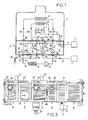
- FIG. 1, of these drawings very schematically shows a mixed central heating boiler, the connection portion of which is connected to the external piping consists of a bar established in accordance with the invention.
- FIG. 2 shows the same bar schematically, but in more detail.
- Figure 3 shows in side view an embodiment of said bar.
- Figure 4 shows in perspective view one of the constituent modules of this bar.
- the combined boiler considered comprises, inside a casing 1, a burner 2 supplied with pressurized combustible gas from a network 3 via a gas pipe 4 associated with safety means (not shown) and with a tap 5.
- the closed heating circuit comprises, inside the casing 1, an exchanger 6 in which the circulating water collects the calories generated by the flames 7 of the burner 2 and, outside said casing, a pipe 8 passing successively the heating radiators 9 and a circulation pump 10.
- the drawing-off circuit successively comprises, from an external source of pressurized water 11 generally constituted by a city network, an external intake pipe 12, an exchanger 13 inside the casing 1 also making it possible to collect the calories produced by the flames 7 and an outlet pipe 14 ending in at least one tap 15.
- connection portion R which is interposed between the external pipes 8, 12 and 14 and the internal pipes comprising the exchangers 6 and 13.
- connection portion R is here constituted by a set of molded hard plastic modules which are juxtaposed against each other and joined together by tie rods 16 advantageously constituted by rods whose threaded ends cooperate with tightening nuts 17.
- the different modules are arranged in such a way that their simple juxtaposition connects the different short-circuit sections 26, 31, 38 and 46 comprised by the four modules end-to-end in a sealed manner.
- end pieces of sections to be mutually connected are arranged so as to fit one into the other with the interposition of an O-ring 47 housed in an appropriate groove hollowed out in the external cylindrical face of the male end piece. of each pair end caps.
- connection strip R it suffices then to place three plugs (not shown) respectively on the three mouths 18.33 and 40 of the connection strip R, as shown diagrammatically by crosses in FIG. 1, then to open the various taps 23.37 , 39 and 45.
- the third module C is associated with a safety member 48 (FIG. 2) arranged so as to, on the one hand, make it possible to supply the heating circuit, and more precisely the short-circuit pipe. 26,31, 38,46 by the pressurized water from the network and, on the other hand, making it impossible to return to the conduit 36 -and therefore to the supply network 11- of a portion of the water circulating in the heating circuit and more precisely in the short-circuit pipe above.
- a safety member 48 FIG. 2
- This member 48 is connected to the discharge pipe 25 of the first module by means of discharge sections 49, 50, 51 understood respectively by the first three modules A, B and C and arranged, like the short sections. above circuit, so as to be automatically connected end to end in a sealed and automatic manner by the simple mutual juxtaposition of the three modules considered.
- the barrier member 39 is here a valve with two valves 52 and 53 mounted in series on the same rod 54 and adapted to communicate respectively the conduit 36 with a compartment a and the section 38 with a compartment b both crossed by said rod and connected to each other through safety member 48.
- a third compartment c disposed between the two compartments a and b and also crossed by the rod 54 is brought into the open air through a conduit 55.
- This conduit is used to evacuate to the outside the few drops of water which could leak at the level of the crossings, by the rod 54, of the dividing partitions between, on the one hand, the compartments a and c and, on the other hand, the two compartments b and c , crossed, which are sealed with O-rings or the like 56.
- valves 52 and 53 are closed simultaneously by actuation of a single rod 54.
- the security member 48 sometimes called a "backflow preventer" can be constituted in any manner known per se and is not the subject of the present invention.
- This member 48 can be incorporated into module C or attached to it, in particular using screws.
- the fourth module D advantageously comprises a relief valve 57 (FIG. 2) mounted on the section 46, this valve being biased towards its closed position by a spring 58 calibrated so that it opens only if it exists in the heating circuit a pressure drop exceeding a given threshold, for example due to the closing of too many thermostatic valves.
- the isolation valve 45 fitted to the fourth module D is advantageously fitted with a filter 59 which is easily removable when the valve in question is closed, a filter making it possible to retain impurities coming from the heating circuit and to prevent their sending into the body. boiler heating.
- the fifth module E comprising an inlet 60 connectable to the piping 4 for external supply of pressurized gas, an outlet 61 connectable to the piping 4 for supplying gas to the burner 2 of the boiler, a conduit 62 connecting this inlet to this outlet and the isolation valve 5 above mounted on said conduit 62.
- the molded material making up the modules can be different according to the modules, and adapted to the operating temperatures, the modules assigned to a circulation of cold or lukewarm water (C and D) or to the electrical connections (F) can be made of a less efficient material than those assigned to a circulation of hot water (A and B) or that of gas (E).
- This material could be a metal such as an aluminum alloy, but is preferably an injected plastic, which has many advantages (economy, lightness, resistance to corrosion ).
- This plastic material is for example a polyether sulfone (commonly called PPS), a polyether imide (PEI) or a polyphenylene sulfone (PES) for modules A, B, C, D and F and even for a peripheral portion of module E, the internal portion of said module E, directly in contact with the gas, then being formed by a metal core.
- PPS polyether sulfone
- PEI polyether imide
- PES polyphenylene sulfone
- Said material can also be an epoxy resin to constitute the entire module E.
- Each molded module advantageously comprises a prismatic or cylindrical peripheral belt 63 (FIG. 4) whose contour is substantially rectangular with rounded corners, four rectilinear channels 64 respectively disposed at the four corners of this belt and intended to receive the tie rods 16 and a plurality of straight or bent tubular sections T braced by generally flat sails V extending perpendicular to the generatrices of the prism or cylinder defining the belt.
- module B which has been shown isolated in perspective in FIG. 4 is module B.
- said strip R is previously mounted on a wall, at a relatively great distance from it, for example of the order of 20 cm, using two metal cheeks 66 crossed by the ends of the tie rods 16 .
- connections with the external pipes 21, 14, 12, 43 and 4 can then be easily carried out on the waiting inputs and outputs 20, 29, 35, 42 and 60, behind the bar R, between it and the wall, in particular using screw connections.
- connection of the boiler to the bar R thus mounted and connected is then carried out by placing this boiler above this bar, the ends of the pipes 19, 28, 34, 41 and 4 internal to said boiler opening side by side towards the bottom below it, then lowering the boiler so as to juxtapose suitable connecting members terminating said end pieces against those which are on standby in 18,27,33,40 and 61 and finally by assembling the juxtaposed fittings two by two.
Landscapes
- Engineering & Computer Science (AREA)
- General Engineering & Computer Science (AREA)
- Chemical & Material Sciences (AREA)
- Thermal Sciences (AREA)
- Combustion & Propulsion (AREA)
- Mechanical Engineering (AREA)
- Physics & Mathematics (AREA)
- Steam Or Hot-Water Central Heating Systems (AREA)
- Fluidized-Bed Combustion And Resonant Combustion (AREA)
- Heat-Pump Type And Storage Water Heaters (AREA)
- Control Of Steam Boilers And Waste-Gas Boilers (AREA)
- Lining Or Joining Of Plastics Or The Like (AREA)
- Engine Equipment That Uses Special Cycles (AREA)
- General Preparation And Processing Of Foods (AREA)
- Instantaneous Water Boilers, Portable Hot-Water Supply Apparatuses, And Control Of Portable Hot-Water Supply Apparatuses (AREA)
Priority Applications (1)
| Application Number | Priority Date | Filing Date | Title |
|---|---|---|---|
| AT91401904T ATE93308T1 (de) | 1990-07-13 | 1991-07-09 | Kombinierter zentralheizungskessel. |
Applications Claiming Priority (2)
| Application Number | Priority Date | Filing Date | Title |
|---|---|---|---|
| FR9008961 | 1990-07-13 | ||
| FR9008961A FR2664679B1 (fr) | 1990-07-13 | 1990-07-13 | Perfectionnements apportes aux chaudieres mixtes de chauffage central. |
Publications (2)
| Publication Number | Publication Date |
|---|---|
| EP0466576A1 EP0466576A1 (fr) | 1992-01-15 |
| EP0466576B1 true EP0466576B1 (fr) | 1993-08-18 |
Family
ID=9398697
Family Applications (1)
| Application Number | Title | Priority Date | Filing Date |
|---|---|---|---|
| EP91401904A Expired - Lifetime EP0466576B1 (fr) | 1990-07-13 | 1991-07-09 | Perfectionnements apportés aux chaudières mixtes de chauffage central |
Country Status (17)
| Country | Link |
|---|---|
| US (1) | US5165596A (cs) |
| EP (1) | EP0466576B1 (cs) |
| JP (1) | JPH04227428A (cs) |
| KR (1) | KR920003001A (cs) |
| AT (1) | ATE93308T1 (cs) |
| AU (1) | AU637244B2 (cs) |
| CA (1) | CA2046233A1 (cs) |
| CS (1) | CS208791A3 (cs) |
| DE (1) | DE69100278T2 (cs) |
| ES (1) | ES2044699T3 (cs) |
| FR (1) | FR2664679B1 (cs) |
| HU (1) | HUT58896A (cs) |
| MA (1) | MA22211A1 (cs) |
| PL (1) | PL167616B1 (cs) |
| PT (1) | PT98301B (cs) |
| TN (1) | TNSN91057A1 (cs) |
| TR (1) | TR25332A (cs) |
Families Citing this family (14)
| Publication number | Priority date | Publication date | Assignee | Title |
|---|---|---|---|---|
| EP0644383A1 (en) * | 1993-09-17 | 1995-03-22 | Atag Verwarming B.V. | Intergrated unit for use in a heating apparatus |
| AT400625B (de) * | 1994-05-27 | 1996-02-26 | Vaillant Gmbh | Anlage zur heiz- und brauchwasserbereitung mit einem gasbeheizten brenner und einem wärmetauscher |
| US5809755A (en) * | 1994-12-16 | 1998-09-22 | Wright Manufacturing, Inc. | Power mower with riding platform for supporting standing operator |
| DE19632605A1 (de) † | 1996-08-13 | 1998-02-19 | Wilo Gmbh | Hydraulikbaugruppe für eine kombinierte Heizwasser- und Sanitärwasseranlage |
| US6145139A (en) * | 1998-01-31 | 2000-11-14 | Bonn; Stephen P. | Supplementary water heater system for swimming pools and spa |
| IT1308197B1 (it) * | 1999-02-24 | 2001-12-10 | Fontecal S P A | Gruppo idraulico componibile. |
| JP3590772B2 (ja) * | 2001-01-16 | 2004-11-17 | Smc株式会社 | センサ付き電磁弁 |
| SE0100345D0 (sv) | 2001-02-02 | 2001-02-02 | Saab Ab | Antennsystem och reflektorelement i antennsystem |
| DE102004020718A1 (de) * | 2004-04-28 | 2005-11-24 | BSH Bosch und Siemens Hausgeräte GmbH | Warmwasserbereiter, insbesondere Warmwasserspeicher |
| CA2503056A1 (fr) | 2005-04-07 | 2006-10-07 | Louis Cloutier | Chaudiere avec anti-chambre et echangeur helicoidal |
| JP5340382B2 (ja) * | 2009-04-17 | 2013-11-13 | 三菱電機株式会社 | 弁ブロック及び弁ブロックユニット |
| EP2397777B1 (de) * | 2010-06-19 | 2016-08-03 | Grundfos Management A/S | Gehäuseeinheit für eine Heizungsanlage |
| US10012393B2 (en) * | 2014-12-22 | 2018-07-03 | Intellihot, Inc. | Combined hot water and space heating and conditioning system including heat pump |
| JP6972704B2 (ja) * | 2017-06-26 | 2021-11-24 | 株式会社ノーリツ | 給湯システム |
Family Cites Families (6)
| Publication number | Priority date | Publication date | Assignee | Title |
|---|---|---|---|---|
| FR1334629A (fr) * | 1962-08-17 | 1963-08-09 | Saunier Duval | Perfectionnement aux appareils du type chauffe-eau, chauffe-bains et chaudières murales à gaz |
| NL6708548A (cs) * | 1966-06-28 | 1967-12-29 | ||
| FR2082328A5 (cs) * | 1970-03-11 | 1971-12-10 | Saunier Duval | |
| FR2398271A1 (fr) * | 1977-07-22 | 1979-02-16 | Addulor | Perfectionnements aux ensembles pour raccorder une chaudiere murale a eau chaude a ses tuyauteries de desserte |
| US4657047A (en) * | 1984-12-10 | 1987-04-14 | Nordson Corporation | Modular color changers with improved valves and manifolds |
| US5076494A (en) * | 1989-12-18 | 1991-12-31 | Carrier Corporation | Integrated hot water supply and space heating system |
-
1990
- 1990-07-13 FR FR9008961A patent/FR2664679B1/fr not_active Expired - Fee Related
-
1991
- 1991-07-04 CA CA 2046233 patent/CA2046233A1/en not_active Abandoned
- 1991-07-05 US US07/726,193 patent/US5165596A/en not_active Expired - Fee Related
- 1991-07-08 MA MA22484A patent/MA22211A1/fr unknown
- 1991-07-08 CS CS912087A patent/CS208791A3/cs unknown
- 1991-07-09 DE DE91401904T patent/DE69100278T2/de not_active Expired - Fee Related
- 1991-07-09 ES ES91401904T patent/ES2044699T3/es not_active Expired - Lifetime
- 1991-07-09 AT AT91401904T patent/ATE93308T1/de not_active IP Right Cessation
- 1991-07-09 EP EP91401904A patent/EP0466576B1/fr not_active Expired - Lifetime
- 1991-07-10 KR KR1019910011700A patent/KR920003001A/ko not_active Withdrawn
- 1991-07-11 PT PT98301A patent/PT98301B/pt not_active IP Right Cessation
- 1991-07-11 TR TR68291A patent/TR25332A/xx unknown
- 1991-07-12 HU HU912358A patent/HUT58896A/hu unknown
- 1991-07-12 AU AU80360/91A patent/AU637244B2/en not_active Ceased
- 1991-07-12 PL PL91291045A patent/PL167616B1/pl unknown
- 1991-07-12 TN TNSN91057 patent/TNSN91057A1/fr unknown
- 1991-07-15 JP JP3198254A patent/JPH04227428A/ja active Pending
Also Published As
| Publication number | Publication date |
|---|---|
| HU912358D0 (en) | 1991-12-30 |
| PT98301B (pt) | 1998-12-31 |
| DE69100278D1 (de) | 1993-09-23 |
| FR2664679A1 (fr) | 1992-01-17 |
| ATE93308T1 (de) | 1993-09-15 |
| FR2664679B1 (fr) | 1993-07-30 |
| AU637244B2 (en) | 1993-05-20 |
| KR920003001A (ko) | 1992-02-28 |
| US5165596A (en) | 1992-11-24 |
| JPH04227428A (ja) | 1992-08-17 |
| TR25332A (tr) | 1993-01-01 |
| EP0466576A1 (fr) | 1992-01-15 |
| TNSN91057A1 (fr) | 1992-10-25 |
| DE69100278T2 (de) | 1994-03-10 |
| CS208791A3 (en) | 1992-02-19 |
| PL167616B1 (pl) | 1995-09-30 |
| CA2046233A1 (en) | 1992-01-14 |
| MA22211A1 (fr) | 1992-04-01 |
| PL291045A1 (en) | 1992-03-23 |
| PT98301A (pt) | 1993-08-31 |
| ES2044699T3 (es) | 1994-01-01 |
| AU8036091A (en) | 1992-01-16 |
| HUT58896A (en) | 1992-03-30 |
Similar Documents
| Publication | Publication Date | Title |
|---|---|---|
| EP0466576A1 (fr) | Perfectionnements apportés aux chaudières mixtes de chauffage central | |
| FR2796700A3 (fr) | Systeme de vannes de repartition | |
| EP1155271B1 (fr) | Echangeur thermique a plaques, a vanne integree | |
| CA2434599A1 (fr) | Module de bloc changeur de teinte pour installation de peinture | |
| EP1196725B1 (fr) | Dispositif d'alimentation d'un canon a neige | |
| FR2807793A1 (fr) | Module d'interface pour ilot de distributeurs electropneumatiques | |
| EP3809061A1 (fr) | Equipement pour raccorder à l'air extérieur au moins un appareil thermodynamique à air | |
| FR2478807A1 (fr) | Boite collectrice de raccordement pour appareil d'echanges thermiques | |
| EP0022119A2 (fr) | Système de collecteurs pour conduites dans une habitation orientable | |
| EP1262743A1 (fr) | Dispositif de raccordement pour poste de comptage d'eau | |
| FR2550605A1 (fr) | Bloc de derivation pour circuit hydraulique, notamment de chauffage | |
| BE1032004B1 (fr) | Élément distributeur de dispositif récupérateur de chaleur | |
| FR2614680A1 (fr) | Absorbeur-stockeur souple d'energie solaire | |
| EP1036297A1 (fr) | Echangeur de chaleur air-liquide pour circuit hydraulique de vehicule | |
| EP3093601B1 (fr) | Echangeur thermique | |
| FR3103884A1 (fr) | Cuve de stockage compacte et ensemble chauffe-eau sanitaire | |
| FR2820815A1 (fr) | Organe d'alimentation ou d'evacuation pour radiateur | |
| EP4713622A1 (fr) | Dispositif de construction d'une sous-station de chauffage urbain et sous-station le comportant | |
| FR2969254A1 (fr) | Boitier repartiteur d'un fluide caloporteur dans une installation comprenant des echangeurs de chaleur et des circuits de captage et de restitution de chaleur | |
| FR2776380A1 (fr) | Coffret hors sol de raccordement a un reseau de gaz | |
| FR2820810A1 (fr) | Dispositif de recyclage de l'eau chaude sanitaire dans un reseau de distribution dont le tube de recyclage est place a l'interieur du tube de distribution. dispositif applicable a d'autre fluides | |
| FR2549571A1 (fr) | Raccord tubulaire deformable | |
| FR2815105A1 (fr) | Robinet d'eau antigel | |
| FR2896291A1 (fr) | Robinet du type melangeur a raccordement simplifie | |
| FR2820494A1 (fr) | Dispositif de liaison entre un ballon d'eau et un systeme de production d'eau chaude sanitaire et d'eau chaude de chauffage |
Legal Events
| Date | Code | Title | Description |
|---|---|---|---|
| PUAI | Public reference made under article 153(3) epc to a published international application that has entered the european phase |
Free format text: ORIGINAL CODE: 0009012 |
|
| AK | Designated contracting states |
Kind code of ref document: A1 Designated state(s): AT BE CH DE DK ES GB GR IT LI LU NL SE |
|
| 17P | Request for examination filed |
Effective date: 19920226 |
|
| 17Q | First examination report despatched |
Effective date: 19920812 |
|
| GRAA | (expected) grant |
Free format text: ORIGINAL CODE: 0009210 |
|
| AK | Designated contracting states |
Kind code of ref document: B1 Designated state(s): AT BE CH DE DK ES GB GR IT LI LU NL SE |
|
| PG25 | Lapsed in a contracting state [announced via postgrant information from national office to epo] |
Ref country code: SE Effective date: 19930818 Ref country code: GR Free format text: LAPSE BECAUSE OF FAILURE TO SUBMIT A TRANSLATION OF THE DESCRIPTION OR TO PAY THE FEE WITHIN THE PRESCRIBED TIME-LIMIT Effective date: 19930818 Ref country code: DK Effective date: 19930818 |
|
| REF | Corresponds to: |
Ref document number: 93308 Country of ref document: AT Date of ref document: 19930915 Kind code of ref document: T |
|
| GBT | Gb: translation of ep patent filed (gb section 77(6)(a)/1977) |
Effective date: 19930817 |
|
| REF | Corresponds to: |
Ref document number: 69100278 Country of ref document: DE Date of ref document: 19930923 |
|
| ITF | It: translation for a ep patent filed | ||
| REG | Reference to a national code |
Ref country code: ES Ref legal event code: FG2A Ref document number: 2044699 Country of ref document: ES Kind code of ref document: T3 |
|
| PLBE | No opposition filed within time limit |
Free format text: ORIGINAL CODE: 0009261 |
|
| STAA | Information on the status of an ep patent application or granted ep patent |
Free format text: STATUS: NO OPPOSITION FILED WITHIN TIME LIMIT |
|
| 26N | No opposition filed | ||
| EPTA | Lu: last paid annual fee | ||
| PGFP | Annual fee paid to national office [announced via postgrant information from national office to epo] |
Ref country code: AT Payment date: 19950626 Year of fee payment: 5 |
|
| PGFP | Annual fee paid to national office [announced via postgrant information from national office to epo] |
Ref country code: NL Payment date: 19950627 Year of fee payment: 5 |
|
| PGFP | Annual fee paid to national office [announced via postgrant information from national office to epo] |
Ref country code: GB Payment date: 19950703 Year of fee payment: 5 |
|
| PGFP | Annual fee paid to national office [announced via postgrant information from national office to epo] |
Ref country code: ES Payment date: 19950711 Year of fee payment: 5 |
|
| PGFP | Annual fee paid to national office [announced via postgrant information from national office to epo] |
Ref country code: CH Payment date: 19950717 Year of fee payment: 5 |
|
| PGFP | Annual fee paid to national office [announced via postgrant information from national office to epo] |
Ref country code: LU Payment date: 19950801 Year of fee payment: 5 |
|
| PGFP | Annual fee paid to national office [announced via postgrant information from national office to epo] |
Ref country code: BE Payment date: 19950804 Year of fee payment: 5 |
|
| PG25 | Lapsed in a contracting state [announced via postgrant information from national office to epo] |
Ref country code: LU Free format text: LAPSE BECAUSE OF NON-PAYMENT OF DUE FEES Effective date: 19960709 Ref country code: GB Effective date: 19960709 Ref country code: AT Effective date: 19960709 |
|
| PG25 | Lapsed in a contracting state [announced via postgrant information from national office to epo] |
Ref country code: ES Free format text: LAPSE BECAUSE OF EXPIRATION OF PROTECTION Effective date: 19960710 |
|
| PG25 | Lapsed in a contracting state [announced via postgrant information from national office to epo] |
Ref country code: LI Effective date: 19960731 Ref country code: CH Effective date: 19960731 Ref country code: BE Effective date: 19960731 |
|
| BERE | Be: lapsed |
Owner name: CHAFFOTEAUX ET MAURY Effective date: 19960731 |
|
| PG25 | Lapsed in a contracting state [announced via postgrant information from national office to epo] |
Ref country code: NL Effective date: 19970201 |
|
| GBPC | Gb: european patent ceased through non-payment of renewal fee |
Effective date: 19960709 |
|
| REG | Reference to a national code |
Ref country code: CH Ref legal event code: PL |
|
| NLV4 | Nl: lapsed or anulled due to non-payment of the annual fee |
Effective date: 19970201 |
|
| REG | Reference to a national code |
Ref country code: ES Ref legal event code: FD2A Effective date: 19990601 |
|
| PGFP | Annual fee paid to national office [announced via postgrant information from national office to epo] |
Ref country code: DE Payment date: 20040702 Year of fee payment: 14 |
|
| PG25 | Lapsed in a contracting state [announced via postgrant information from national office to epo] |
Ref country code: IT Free format text: LAPSE BECAUSE OF NON-PAYMENT OF DUE FEES;WARNING: LAPSES OF ITALIAN PATENTS WITH EFFECTIVE DATE BEFORE 2007 MAY HAVE OCCURRED AT ANY TIME BEFORE 2007. THE CORRECT EFFECTIVE DATE MAY BE DIFFERENT FROM THE ONE RECORDED. Effective date: 20050709 |
|
| PG25 | Lapsed in a contracting state [announced via postgrant information from national office to epo] |
Ref country code: DE Free format text: LAPSE BECAUSE OF NON-PAYMENT OF DUE FEES Effective date: 20060201 |