EP0466834B1 - Regelungsverfahren und vorrichtung sowie verfahren in kompostierung - Google Patents
Regelungsverfahren und vorrichtung sowie verfahren in kompostierung Download PDFInfo
- Publication number
- EP0466834B1 EP0466834B1 EP90907742A EP90907742A EP0466834B1 EP 0466834 B1 EP0466834 B1 EP 0466834B1 EP 90907742 A EP90907742 A EP 90907742A EP 90907742 A EP90907742 A EP 90907742A EP 0466834 B1 EP0466834 B1 EP 0466834B1
- Authority
- EP
- European Patent Office
- Prior art keywords
- probe
- organic matter
- temperature
- vessel
- ram
- Prior art date
- Legal status (The legal status is an assumption and is not a legal conclusion. Google has not performed a legal analysis and makes no representation as to the accuracy of the status listed.)
- Expired - Lifetime
Links
- 238000009264 composting Methods 0.000 title claims abstract description 47
- 238000000034 method Methods 0.000 title claims abstract description 27
- 238000012544 monitoring process Methods 0.000 title claims abstract description 18
- 239000000523 sample Substances 0.000 claims abstract description 74
- 239000005416 organic matter Substances 0.000 claims abstract description 55
- 230000001105 regulatory effect Effects 0.000 claims abstract description 9
- 238000000605 extraction Methods 0.000 claims abstract description 3
- 238000000354 decomposition reaction Methods 0.000 claims description 2
- 230000000694 effects Effects 0.000 claims 1
- 238000005056 compaction Methods 0.000 abstract description 2
- 238000005273 aeration Methods 0.000 description 28
- 239000000463 material Substances 0.000 description 6
- 239000002361 compost Substances 0.000 description 4
- 239000012530 fluid Substances 0.000 description 4
- 238000012806 monitoring device Methods 0.000 description 4
- 238000006243 chemical reaction Methods 0.000 description 3
- 238000004891 communication Methods 0.000 description 2
- 230000008878 coupling Effects 0.000 description 2
- 238000010168 coupling process Methods 0.000 description 2
- 238000005859 coupling reaction Methods 0.000 description 2
- 239000010813 municipal solid waste Substances 0.000 description 2
- 239000010815 organic waste Substances 0.000 description 2
- 239000010802 sludge Substances 0.000 description 2
- 238000004065 wastewater treatment Methods 0.000 description 2
- 238000010276 construction Methods 0.000 description 1
- 230000001276 controlling effect Effects 0.000 description 1
- 238000001035 drying Methods 0.000 description 1
- 238000002347 injection Methods 0.000 description 1
- 239000007924 injection Substances 0.000 description 1
- 230000002452 interceptive effect Effects 0.000 description 1
- 238000005259 measurement Methods 0.000 description 1
- 239000011368 organic material Substances 0.000 description 1
- 230000035515 penetration Effects 0.000 description 1
- 239000002364 soil amendment Substances 0.000 description 1
- 239000002910 solid waste Substances 0.000 description 1
- 230000000087 stabilizing effect Effects 0.000 description 1
- 229910001220 stainless steel Inorganic materials 0.000 description 1
- 239000010935 stainless steel Substances 0.000 description 1
- 230000003068 static effect Effects 0.000 description 1
- XLYOFNOQVPJJNP-UHFFFAOYSA-N water Substances O XLYOFNOQVPJJNP-UHFFFAOYSA-N 0.000 description 1
Images

Classifications
-
- G—PHYSICS
- G01—MEASURING; TESTING
- G01K—MEASURING TEMPERATURE; MEASURING QUANTITY OF HEAT; THERMALLY-SENSITIVE ELEMENTS NOT OTHERWISE PROVIDED FOR
- G01K13/00—Thermometers specially adapted for specific purposes
- G01K13/10—Thermometers specially adapted for specific purposes for measuring temperature within piled or stacked materials
-
- C—CHEMISTRY; METALLURGY
- C05—FERTILISERS; MANUFACTURE THEREOF
- C05F—ORGANIC FERTILISERS NOT COVERED BY SUBCLASSES C05B, C05C, e.g. FERTILISERS FROM WASTE OR REFUSE
- C05F17/00—Preparation of fertilisers characterised by biological or biochemical treatment steps, e.g. composting or fermentation
- C05F17/90—Apparatus therefor
- C05F17/921—Devices in which the material is conveyed essentially horizontally between inlet and discharge means
- C05F17/936—Tunnels
-
- C—CHEMISTRY; METALLURGY
- C05—FERTILISERS; MANUFACTURE THEREOF
- C05F—ORGANIC FERTILISERS NOT COVERED BY SUBCLASSES C05B, C05C, e.g. FERTILISERS FROM WASTE OR REFUSE
- C05F17/00—Preparation of fertilisers characterised by biological or biochemical treatment steps, e.g. composting or fermentation
- C05F17/90—Apparatus therefor
- C05F17/993—Arrangements for measuring process parameters, e.g. temperature, pressure or humidity
-
- Y—GENERAL TAGGING OF NEW TECHNOLOGICAL DEVELOPMENTS; GENERAL TAGGING OF CROSS-SECTIONAL TECHNOLOGIES SPANNING OVER SEVERAL SECTIONS OF THE IPC; TECHNICAL SUBJECTS COVERED BY FORMER USPC CROSS-REFERENCE ART COLLECTIONS [XRACs] AND DIGESTS
- Y02—TECHNOLOGIES OR APPLICATIONS FOR MITIGATION OR ADAPTATION AGAINST CLIMATE CHANGE
- Y02P—CLIMATE CHANGE MITIGATION TECHNOLOGIES IN THE PRODUCTION OR PROCESSING OF GOODS
- Y02P20/00—Technologies relating to chemical industry
- Y02P20/141—Feedstock
- Y02P20/145—Feedstock the feedstock being materials of biological origin
-
- Y—GENERAL TAGGING OF NEW TECHNOLOGICAL DEVELOPMENTS; GENERAL TAGGING OF CROSS-SECTIONAL TECHNOLOGIES SPANNING OVER SEVERAL SECTIONS OF THE IPC; TECHNICAL SUBJECTS COVERED BY FORMER USPC CROSS-REFERENCE ART COLLECTIONS [XRACs] AND DIGESTS
- Y02—TECHNOLOGIES OR APPLICATIONS FOR MITIGATION OR ADAPTATION AGAINST CLIMATE CHANGE
- Y02W—CLIMATE CHANGE MITIGATION TECHNOLOGIES RELATED TO WASTEWATER TREATMENT OR WASTE MANAGEMENT
- Y02W30/00—Technologies for solid waste management
- Y02W30/40—Bio-organic fraction processing; Production of fertilisers from the organic fraction of waste or refuse
-
- Y—GENERAL TAGGING OF NEW TECHNOLOGICAL DEVELOPMENTS; GENERAL TAGGING OF CROSS-SECTIONAL TECHNOLOGIES SPANNING OVER SEVERAL SECTIONS OF THE IPC; TECHNICAL SUBJECTS COVERED BY FORMER USPC CROSS-REFERENCE ART COLLECTIONS [XRACs] AND DIGESTS
- Y10—TECHNICAL SUBJECTS COVERED BY FORMER USPC
- Y10S—TECHNICAL SUBJECTS COVERED BY FORMER USPC CROSS-REFERENCE ART COLLECTIONS [XRACs] AND DIGESTS
- Y10S435/00—Chemistry: molecular biology and microbiology
- Y10S435/813—Continuous fermentation
Definitions
- the invention relates to a method and apparatus for monitoring temperature during aerobic composting of organic waste matter.
- This temperature control is a critical part of the composting process. If the temperature of the organic matter is too low, the process will take too long to complete. On the other hand, if the temperature is too high, the process breaks down.
- the key to economically operating whatever equipment is used in the composting process is to achieve an optimum temperature for a selected time period in order to quickly and completely process the organic matter.
- One example of such a temperature and time period is to achieve an optimum temperature of 55°C for three days. In order to achieve this, the temperature of the organic matter must be controlled, and in order to control the temperature, some means of temperature monitoring is required.
- a monitoring device In order to control the temperature of the composting mass to the desired temperature in the horizontal composters using air to accelerate the process, a monitoring device is necessary to provide the temperature at a plurality of points throughout the mass.
- Temperature monitoring devices located at the perimeter of the composting chamber cannot provide appropriate temperature readings. Thus, a temperature monitoring device or method which probes into the mass of the organic matter is desired.
- a problem connected with monitoring temperature at the mid-point is related to the fact that the composting mass of organic matter moves through the composter and therefore any monitoring device used must accommodate such movement.
- GB-A-2199820 discloses the use of an elongate probe to measure the internal temperature of a static compost mass.
- the present invention provides a temperature monitoring apparatus for monitoring the temperature within a mass of organic matter moved through a composting vessel by means of a compacting ram.
- An elongated, stationary probe extends through the vessel from one end toward the other.
- a plurality of temperature measuring devices are mounted along the probe.
- the probe may extend through the ram and be provided with a sleeve for accommodating movement of the ram relative to the probe.
- a decoupling device provides for decoupling of the probe from a mounting base and an extraction device permits the probe to be extracted from the vessel for replacement thereof.
- the probe provides a method of monitoring temperature in the mass and a method of composting by monitoring temperature in the mass and regulating the temperature in response thereto.
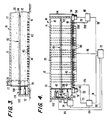
- reference numeral 10 refers generally to a composting apparatus according to the particular exemplary embodiment of the present invention as shown and described herein.
- Composting apparatus 10 includes a hollow vessel 12 defined by walls 14.
- the vessel has a rectangular cross-section such that walls 14 include a floor 16, a top wall 17, and side walls 18 extending in parallel fashion between the floor 16 and top wall 17.
- Walls 14 define a chamber 20 within vessel 12.
- vessel 12 and its internal chamber 20 are elongated so as to take the form of a conduit.
- composting apparatus 10 could be a conventional horizontally oriented composter, with top-to-bottom compost flow, which is modified and improved as discussed in greater detail below.
- an inlet 22 having an infeed conveyor 26, whereby inlet 22 in conjunction with infeed conveyor 26 permits communication with chamber 20 within the vessel 12.
- outlet 28 At the opposite end of vessel 12 is an outlet 28.
- a ram 30 driven by a set of actuators 32, which preferably are hydraulic cylinders but which could also be pneumatic cylinders or screw jacks. If actuators 32 are indeed hydraulic cylinders, they are actuated by a source 34 of pressurized hydraulic fluid shown schematically in Fig. 4, which pressure source 34 communicates with actuators 32 via hydraulic fluid lines 35.
- the source 34 of pressurized hydraulic fluid is a pump feeding hydraulic fluid in the form of oil to actuators 32 via hydraulic line 35 to move the ram 30.
- Organic matter such as sludge from a waste water treatment system or solid waste or garbage, is fed into the composting apparatus 10 via infeed conveyor 26 in a direction shown by arrow 37 (Fig. 1.)
- the organic matter is fed into chamber 20 at the end thereof adjacent inlet 22 and is deposited in front of ram 30.
- Actuators 32 are actuated to move ram 30 in a direction toward outlet 28 in order to advance the charge of organic matter 36 through composting apparatus 10.
- the advancing stroke of ram 30 is shown in phantom lines in Fig. 3.
- the distance between the retracted position of ram 30 as shown in solid lines in Fig. 3 and the fully advanced position as shown in phantom lines in Fig. 3 represents the volume of one charge of organic matter 36 fed into the composting apparatus 10 during one infeed operation. After such an infeed operation, ram 30 remains in this fully advanced position until it is retracted to the solid line position shown in Fig. 3 when the next infeed operation is initiated.
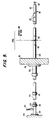
- a temperature probe 82 is preferably formed of stainless steel and comprises a plurality of sections appropriately connected together to provide a desired length. It is contemplated that a first end 104 of probe 82 may be attached to a reaction wall 106 adjacent inlet 22 and extend through ram 30 by means of a sleeve member 108 concentrically disposed on probe 82. Sleeve member 108 is attached to ram 30 via a collar 110. Probe 82 extends in the direction of movement of the organic matter and terminates at a second end 112 adjacent outlet end 28 of apparatus 10. Second end 112 includes an eyebolt 114. In this manner, probe 82 extends through the organic matter 36 and ram 30 is permitted to move relative to probe 82 by virtue of sleeve member 108. Thus, probe 82 is supported at first end 104 by reaction wall 106 and sleeve member 108, and at second end 112 by the mass of organic matter 36.
- At least one of such probes 82 may extend from the outlet end 28 of the vessel 12 toward the inlet end 22 and terminate just short of the advanced position of ram 30 so as not to interfere with the advancing stroke of ram 30.
- Movement of the organic matter 36 during compaction by ram 30 produces stabilizing forces on probe 82 which keep probe 82 in the same relative position in the organic matter 36.
- the sliding motion of the mass along probe 36 cleans the probe surface.
- a coupling 116 defined by a pair of spaced apart collars 118, located between ram 30 and reaction wall 106, is disconnected and a cable may be attached to the longer piece of the probe at 118.
- a second cable may be attached to eyebolt 114 and may be used to pull the probe from the organic matter in the direction of outlet 28. The first cable is pulled into the resulting hole in the compacted organic matter 36 formed by the probe 82. Once the old probe has been removed, the first cable may be attached to a new probe and the new probe pulled toward the inlet 22 into the probe hole in the organic matter 36. The first cable is removed and the new probe is attached at the coupling 116.
- the surface 120 of probe 82 is provided with a plurality of temperature measure devices (TMD's) 83 in such a manner that a group of preferably three TMD's 83 are provided in each zone (to be described later) in a manner such that one TMD is centrally positioned in each zone and adjacent TMD's are equally spaced on opposite sides of the centrally positioned TMD.
- TMD's include thermocouples and resistance temperature devices.
- the three TMD's in each zone are preferably wired in parallel to provide an average readout for each zone. By using three TMD's per zone, the probe 82 will still provide a signal representing the temperature of a zone in the event of failure of one or two of the TMD's in that zone.
- Wires 122 from the TMD's 83 extend through probe 82 and exit at conduit 124 adjacent first end 104.
- a plurality of probes 82 may be used in one composter, the key being that all such probes 82 extend along the composter in the direction of movement of the organic matter 36, i.e., the axis of each probe 82 is parallel with the direction of movement of the mass of organic matter 36.
- Probe 82 of the type described above may be used in connection with a vessel 12 including in the floor 16, a set of floor-mounted diffusers or orifices 40 distributed along virtually the entire length of vessel 12 for providing aeration air thereto.
- These diffusers 40 communicate with chamber 20 of vessel 12 to permit pressurized air to be injected into chamber 20.
- the air injection is accomplished via air passages 42 in floor 16, which air passages are fed by an air header 43 disposed in outlet vessel 12.
- air header 43 communicates with the series of air passages 42 which, in turn, communicate with diffusers 40 for injecting air into chamber 20.
- a source of aeration air provides air for effecting aeration and temperature control of the organic matter 36 to convert it to compost in a known manner.
- the aeration air is generated by a blower 51 driven by electric motor 52.
- Aeration air is fed into air header 43 to then pass through air passages 42 in floor 16 of chamber 20 and thence through diffusers 40 for aeration of the organic matter 36 to aid in composting.
- a selected portion of the set of diffusers or orifices 40 may act as suction orifices or inlets for return of aeration air which has been introduced into the organic matter 36 by others of the diffusers or orifices 40. By providing that some of the orifices 40 act as air returns, circulation through the organic matter 36 may be improved and the temperature better regulated.
- This aeration air return is accomplished via a suction fan 54 driven by a motor 56.
- Suction fan 54 pulls air through valve 200 and communicates with the suction header 58 which, in turn, selectively communicates with a certain portion of the air passages 42.
- air passages 42 When certain of the air passages 42 are in communication with suction header 58, air passages 42 then act as air returns for drawing aeration air from organic matter 36 to enhance circulation of aeration air.
- valves 60 preferably in the form of electronically controlled valves such as solenoid valves.
- a valve 60 will be disposed between each air passage 42 and the air header 43 and suction header 58.
- Separate zones (previously mentioned) of pressure and suction diffusers may be provided. In the particular exemplary embodiment shown and described, there are five zones of four air passages per zone. Each zone may correspond generally with a charge of material fed into vessel 12 by one infeed operation and one stroke of ram 30.
- a zone may hold more or less than one charge of material.
- certain conventional composters have approximately three charges located in a particular zone at a given time. Regardless of the amount of material therein, one such zone may be put under pressure, the next under suction, and so on in an alternating fashion.
- the aeration air system includes an aeration control 64 coupled with the valve 49 and/or the blower 51 which produces aeration air, and more specifically with the motor 52 of that blower.
- Aeration control 64 is preferably electronic and sends electrical signals to valve 49 and/or motor 52 of blower 51 to regulate the intensity of aeration air produced by blower 51.
- suction air control 66 for energizing motor 56 of suction fan 54 and for regulating its/their operation.
- suction air control 66 is electronic.
- both of the controls 64 and 66 be coupled with a master controller 70 shown schematically in Fig. 4.
- Master controller 70 acts as a central station from which aeration air and suction air may be controlled.
- Master controller 70 is connected to the aeration system via line 74 running to aeration control 64.
- aeration-producing control 64 is coupled to motor 52 of blower 51 via line 75 and/or connected to valve 49 via line 201.
- the master controller 70 is preferably also coupled with valves 60 which determines the pattern of which air passages 42 and orifices 40 are under pressure and which, if any, are under suction.
- master controller 70 provides the appropriate signals to valves 60 over a line 76 (Fig. 4).
- Master controller 70 controls the suction air by sending signals to suction control 66 over line 78.
- suction control 66 is coupled with motor 56 of suction fan 54 by line 79 and/or with valve 200 by line 202.
- Master control 70 also controls the operation of the ram 30 which is driven by hydraulic cylinders 32. Further, master controller 70 requires input from temperature probe 82.
- temperature probe 82 preferably extends axially along the geometric center of chamber 20 between inlet 22 and outlet 28 to measure the temperature of the organic matter 36 in the various zones of the composting apparatus 10.
- Signals from the temperature measuring devices 83 in each zone along the length of the probe 82 are preferably fed from wires 122 back over line 84 to master controller 70 to actuate the aeration air in a pattern (e.g., all pressure or a combination of pressure and/or suction) and at an intensity which will produce an optimum temperature in the organic mass as determined by experience and/or by an algorithm or program utilized by master controller 70.
- a pattern e.g., all pressure or a combination of pressure and/or suction
- a suitable temperature control such as a PID (proportional integral derivative) type controller can be incorporated into master controller 70 to receive temperature information via the temperature measuring devices 83 in a given zone or zones of probe 82 and, in response to an undesirable temperature of the organic matter 36 in that zone or zones, controller 70 may automatically actuate one or more of the blower 51, valve 49, suction fan 54 and valve 200 in combination with actuating appropriate valves 60 to cause orifices 40 to act as suction orifices or inlets thereby improving the circulation of aeration air through the organic matter 36 in order to maintain a desired temperature at the appropriate zone or zones penetrated by probe 82.
- PID proportional integral derivative
Landscapes
- Chemical & Material Sciences (AREA)
- Microbiology (AREA)
- Organic Chemistry (AREA)
- Engineering & Computer Science (AREA)
- Biochemistry (AREA)
- Biotechnology (AREA)
- Chemical Kinetics & Catalysis (AREA)
- Life Sciences & Earth Sciences (AREA)
- General Chemical & Material Sciences (AREA)
- Molecular Biology (AREA)
- Health & Medical Sciences (AREA)
- Physics & Mathematics (AREA)
- General Physics & Mathematics (AREA)
- Fertilizers (AREA)
- Processing Of Solid Wastes (AREA)
- Treatment Of Sludge (AREA)
- Alarm Systems (AREA)
Claims (16)
- Kompostiervorrichtung (10) für beschleunigte aerobische Zersetzung organischen Stoffs, umfassend:
einen Kompostierbehälter (12), durch den der organische Stoff zum Bewirken einer Kompostierung hindurchbewegt wird und
eine Einrichtung (40) zum Durchlüften des organischen Stoffs, wenn sich dieser durch den Kompostierbehälter hindurchbewegt;
gekennzeichnet durch
mindestens eine langgestreckte Sonde (82), die sich von einem ersten Ende des Behälters (12) zu einem zweiten Ende des Behälters hin derart erstreckt, daß, wenn der Behälter (12) mit organischem Stoff gefüllt ist, die Sonde (82) durch den sich bewegenden organischen Stoff abgestützt wird; und
mehrere Temperaturmeßgeräte (83), die entlang der Sonde angebracht sind. - Vorrichtung nach Anspruch 1, umfassend:
einen Stößel (30) zum Bewegen des organischen Stoffs von dem ersten Ende des Behälters (12) in Richtung seines zweiten Endes; und
eine Einrichtung (108), die an dem Stößel (30) angebracht ist, um die Bewegung des Stößels relativ zu der Sonde (32) aufzunehmen. - Vorrichtung nach Anspruch 1 oder 2, bei dem die mehreren Temperaturmeßgeräte (83) gruppenweise beabstandet sind.
- Vorrichtung nach einem der Ansprüche 1 bis 3, bei dem die Sonde (82) eine Entkopplungseinrichtung (116) benachbart zu dem ersten Ende des Behälters (12) und eine Extraktionseinrichtung (114) benachbart zu dem zweiten Ende des Behälters (12) aufweist.
- Vorrichtung nach Anspruch 2, bei dem die an dem Stößel angebrachte Einrichtung eine Hülse (108) mit einem Flansch (110) zur Verbindung mit dem Stößel (30) besitzt.
- Vorrichtung nach einem der Ansprüche 1 bis 5, umfassend eine Einrichtung (64, 70) zum Regulieren der Temperatur in einer in dem Behälter (12) definierten Kammer, wobei die Temperaturreguliereinrichtung (64, 70) mit der Sonde (72) gekoppelt ist.
- Vorrichtung nach Anspruch 6, bei der die Kammer länglich ausgebildet ist und einen rechteckigen Querschnitt besitzt.
- Vorrichtung nach Anspruch 7, bei dem sich die Sonde (82) durch die geometrische Mitte des Querschnitts und koaxial bezüglich der Längsachse erstreckt.
- Vorrichtung nach Anspruch 6, umfassend:
eine Hülse (108), die verschieblich auf der Sonde (82) gelagert ist, wobei die Hülse in dem Stößel (30) gelagert ist, damit der Stößel (30) sich relativ zu der Sonde (82) bewegen kann. - Vorrichtung nach Anspruch 9, bei der ein erstes Ende der Sonde (82) in einer Wand (106) benachbart zu dem Stößel (30) gelagert ist, wobei sich die Sonde (82) über die Hülse (108) durch den Stößel (30) hindurch erstreckt.
- Vorrichtung nach Anspruch 10, umfassend:
eine Öse (114), die an ein zweites Ende der Sonde (82) entgegengesetzt dem ersten Ende gekoppelt ist. - Vorrichtung nach einem der Ansprüche 1 bis 11, bei der die Sonde (82) ortsfest ist.
- Verfahren zum Überwachen der Temperatur m einer Masse organischen Stoffs, der durch einen Kompostierbehälter (12) hindurchbewegt wird, umfassend die Schritte:
Umgeben mindestens einer langgestreckten Sonde (82) mit einer Masse zu kompostierenden organischen Stoffs;
Bewegen der Masse organischen Stoffs durch den Kompostierbehälter (12) in der gleichen Richtung, in der sich die langgestreckte Sonde (82) erstreckt; und
Messen der Temperatur im Inneren der Masse organischen Stoffs an mehreren Stellen entlang der Sonde (82). - Kompostierverfahren durch Überwachen der Temperatur einer Masse organischen Stoffs, der durch einen Kompostierbehälter (12) hindurchbewegt wird, und durch davon abhängiges Regulieren der Temperatur, umfassend die Schritte:
Umgeben mindestens einer langgestreckten Sonde mit einer Masse zu kompostierenden organischen Stoffs;
Bewegen der Masse organischen Stoffs durch den Kompostierbehälter (12) in derselben Richtung, in der sich die langgestreckte Sonde (82) erstreckt;
Messen der Temperatur im Inneren der Masse organischen Stoffs an mehreren Stellen entlang der Sonde (82); und
Regulieren der Temperatur in dem Behälter mit Hilfe einer Temperaturreguliereinrichtung (64, 70), die mit der Sonde (82) gekoppelt ist. - Verfahren nach Anspruch 14, bei dem der organische Stoff von einem Stößel (30) bewegt wird.
- Verfahren nach Anspruch 15, gekennzeichnet durch die zusätzlichen Schritte:
Anbringen eines Lagers (108) an der Sonde (82), um die Bewegung des Stößels (30) relativ zu der ortsfesten Sonde (82) aufzunehmen.
Applications Claiming Priority (3)
| Application Number | Priority Date | Filing Date | Title |
|---|---|---|---|
| US07/337,868 US5049486A (en) | 1989-04-14 | 1989-04-14 | Temperature monitoring apparatus and method in a composting system through which organic matter is moved to effect composting |
| US337868 | 1989-04-14 | ||
| PCT/US1990/001118 WO1990012893A1 (en) | 1989-04-14 | 1990-03-09 | Temperature monitoring apparatus and method in a composting system |
Publications (3)
| Publication Number | Publication Date |
|---|---|
| EP0466834A1 EP0466834A1 (de) | 1992-01-22 |
| EP0466834A4 EP0466834A4 (en) | 1992-03-18 |
| EP0466834B1 true EP0466834B1 (de) | 1995-12-27 |
Family
ID=23322364
Family Applications (1)
| Application Number | Title | Priority Date | Filing Date |
|---|---|---|---|
| EP90907742A Expired - Lifetime EP0466834B1 (de) | 1989-04-14 | 1990-03-09 | Regelungsverfahren und vorrichtung sowie verfahren in kompostierung |
Country Status (8)
| Country | Link |
|---|---|
| US (1) | US5049486A (de) |
| EP (1) | EP0466834B1 (de) |
| AT (1) | ATE132199T1 (de) |
| AU (1) | AU5529190A (de) |
| CA (1) | CA1330891C (de) |
| DE (1) | DE69024488T2 (de) |
| ES (1) | ES2085907T3 (de) |
| WO (1) | WO1990012893A1 (de) |
Families Citing this family (20)
| Publication number | Priority date | Publication date | Assignee | Title |
|---|---|---|---|---|
| US5248612A (en) * | 1989-10-30 | 1993-09-28 | Ashbrook-Simon-Hartley Corporation | Apparatus for composting using improved charging and discharging sequence |
| US5204263A (en) * | 1991-09-27 | 1993-04-20 | Bedminster Bioconversion Corporation | Channel cover |
| US5312754A (en) * | 1992-02-27 | 1994-05-17 | Bryan Brown Michael | Composting apparatus and system |
| AT401213B (de) * | 1992-03-11 | 1996-07-25 | Berger Josef | Verfahren zur beeinflussung des verlaufes von unter wärmeentwicklung stattfindenden abbau- und umwandlungsprozessen bei der lagerung bzw. trocknung von grünanteile enthaltenden biologischen substanzen |
| CA2089305C (en) * | 1993-02-11 | 1998-02-03 | James Wright | Continuous composter |
| US5427947A (en) * | 1993-03-25 | 1995-06-27 | Dalos; David E. | Environmental chamber and method for composting solid waste |
| DK136193A (da) * | 1993-12-06 | 1995-06-28 | Vagn Bislev | Komposteringsanlæg til organisk affald, samt fremgangsmåde ved kompostering af sådant affald |
| US5505544A (en) * | 1994-03-17 | 1996-04-09 | Sony Corp. | Chamber temperature uniformity test fixture |
| US5583045A (en) * | 1995-01-30 | 1996-12-10 | Bedminster Bioconversion Corporation | Compost curing and odor control system |
| US6281001B1 (en) | 1995-11-13 | 2001-08-28 | Mcnelly James J. | Process for controlled composting of organic material and for bioremediating soils |
| US6627434B1 (en) | 1995-11-13 | 2003-09-30 | Mcnelly James J. | Method and apparatus for controlled composting and bioremediating |
| DE19654952B4 (de) * | 1996-10-18 | 2012-06-14 | Herhof Verwaltungsgesellschaft Mbh | Ventil für einen Gasführungskanal in einem Kompostierungsbehälter |
| US5846815A (en) * | 1997-05-13 | 1998-12-08 | Wright; James | Continuous composter having self contained aerating zones |
| US5890664A (en) * | 1997-07-22 | 1999-04-06 | Conant, Iii; Jess Austin | Transportable, self-contained, fully automated composter |
| US6481929B1 (en) * | 1998-04-27 | 2002-11-19 | Arcadis Geraghty & Miller | Aerobic bioreduction of municipal solid waste landfill mass |
| JP3292717B2 (ja) * | 1999-12-20 | 2002-06-17 | 株式会社第一コンサルタント | 有機廃棄物の発酵処理装置及び方法 |
| US7520457B1 (en) | 2003-03-31 | 2009-04-21 | Brian Poitras | Automated composting system |
| US8153419B2 (en) | 2006-04-07 | 2012-04-10 | Mcnelly James J | Dual purpose intermodal and bioconversion container |
| FR2918057B1 (fr) | 2007-06-28 | 2011-09-23 | Veolia Proprete | Procede de compostage a sonde mobile et dispositif correspondant |
| GB2457053A (en) * | 2008-01-31 | 2009-08-05 | Soil & Land Consultants Ltd | Compost Monitoring Apparatus |
Citations (1)
| Publication number | Priority date | Publication date | Assignee | Title |
|---|---|---|---|---|
| US4436817A (en) * | 1979-09-15 | 1984-03-13 | Herbert Nemetz | Method and apparatus for aerobic decomposition or drying of organic waste material |
Family Cites Families (4)
| Publication number | Priority date | Publication date | Assignee | Title |
|---|---|---|---|---|
| US3921228A (en) * | 1973-03-13 | 1975-11-25 | Tommy Mikael Sundberg | Decomposition toilet |
| US4707148A (en) * | 1986-04-02 | 1987-11-17 | Thermo Electric Instruments | Temperature sensing device |
| GB2199820B (en) * | 1986-11-25 | 1990-10-10 | Boc Group Plc | Method of composting |
| US4798802A (en) * | 1987-07-28 | 1989-01-17 | Ryan Richard M | Method for accelerating composting of organic matter and composting reactor therefor |
-
1989
- 1989-04-14 US US07/337,868 patent/US5049486A/en not_active Expired - Fee Related
- 1989-09-28 CA CA000613881A patent/CA1330891C/en not_active Expired - Fee Related
-
1990
- 1990-03-09 WO PCT/US1990/001118 patent/WO1990012893A1/en not_active Ceased
- 1990-03-09 DE DE69024488T patent/DE69024488T2/de not_active Expired - Fee Related
- 1990-03-09 ES ES90907742T patent/ES2085907T3/es not_active Expired - Lifetime
- 1990-03-09 AU AU55291/90A patent/AU5529190A/en not_active Abandoned
- 1990-03-09 AT AT90907742T patent/ATE132199T1/de active
- 1990-03-09 EP EP90907742A patent/EP0466834B1/de not_active Expired - Lifetime
Patent Citations (1)
| Publication number | Priority date | Publication date | Assignee | Title |
|---|---|---|---|---|
| US4436817A (en) * | 1979-09-15 | 1984-03-13 | Herbert Nemetz | Method and apparatus for aerobic decomposition or drying of organic waste material |
Also Published As
| Publication number | Publication date |
|---|---|
| EP0466834A4 (en) | 1992-03-18 |
| DE69024488T2 (de) | 1996-08-22 |
| ATE132199T1 (de) | 1996-01-15 |
| WO1990012893A1 (en) | 1990-11-01 |
| EP0466834A1 (de) | 1992-01-22 |
| AU5529190A (en) | 1990-11-16 |
| US5049486A (en) | 1991-09-17 |
| DE69024488D1 (de) | 1996-02-08 |
| ES2085907T3 (es) | 1996-06-16 |
| CA1330891C (en) | 1994-07-26 |
Similar Documents
| Publication | Publication Date | Title |
|---|---|---|
| EP0466834B1 (de) | Regelungsverfahren und vorrichtung sowie verfahren in kompostierung | |
| EP0449946B1 (de) | Verfahren und vorrichtung zur verkleidung von bauelementen | |
| CA1151784A (en) | Method and apparatus for aerobic decomposition or drying of organic waste material | |
| JP3441731B2 (ja) | 連続堆肥化装置 | |
| TW254862B (de) | ||
| SG43017A1 (en) | Apparatus and method for constructing compacted ganular or stonee columns in soil masses | |
| EP0426704B1 (de) | Kompostierungsverfahren unter verwendung einer geneigten kufe | |
| DE19541866C2 (de) | Verfahren zum hydrothermalen Härten und Trocknen von CSH-gebundenen Formkörpern sowie Vorrichtung zur Durchführung des Verfahrens | |
| CZ288987B6 (cs) | Způsob mikrobiologického odbourání organických odpadů a zařízení | |
| US20020100428A1 (en) | Composting structure | |
| EP0691316B1 (de) | Verfahren und Vorrichtung zur aeroben Zersetzung von organischen Bestandteilen | |
| US5248612A (en) | Apparatus for composting using improved charging and discharging sequence | |
| CA2427019C (en) | Composting in a pressurized aeration vessel | |
| EP0498796B1 (de) | Verfahren und vorrichtung zur kompostierung unter anwendung einer verbesserten beschickungs- und entnahmereihenfolge | |
| CA2005246A1 (en) | Composting method and apparatus utilizing inclined vessel | |
| EP0501319B1 (de) | Kompostieranlage zur Kompostierung von Abfällen | |
| FI962970A0 (fi) | Menetelmä ja laite oraanisen aineen kompostoimiseksi | |
| WO2002060837A2 (en) | Composting structure | |
| KR960007033Y1 (ko) | 섬유질소재의 퇴비화 장치 | |
| US20040066702A1 (en) | Wall mounted compost irrigation system | |
| DE29604034U1 (de) | Pilzsubstrat- und Kompostzubereitungsanlage | |
| AU2002210279A1 (en) | Method and apparatus for aerating organic waste material |
Legal Events
| Date | Code | Title | Description |
|---|---|---|---|
| PUAI | Public reference made under article 153(3) epc to a published international application that has entered the european phase |
Free format text: ORIGINAL CODE: 0009012 |
|
| 17P | Request for examination filed |
Effective date: 19911010 |
|
| AK | Designated contracting states |
Kind code of ref document: A1 Designated state(s): AT BE CH DE DK ES FR GB IT LI LU NL SE |
|
| A4 | Supplementary search report drawn up and despatched |
Effective date: 19920129 |
|
| AK | Designated contracting states |
Kind code of ref document: A4 Designated state(s): AT BE CH DE DK ES FR GB IT LI LU NL SE |
|
| 17Q | First examination report despatched |
Effective date: 19940318 |
|
| GRAA | (expected) grant |
Free format text: ORIGINAL CODE: 0009210 |
|
| AK | Designated contracting states |
Kind code of ref document: B1 Designated state(s): AT BE CH DE DK ES FR GB IT LI LU NL SE |
|
| PG25 | Lapsed in a contracting state [announced via postgrant information from national office to epo] |
Ref country code: NL Free format text: LAPSE BECAUSE OF FAILURE TO SUBMIT A TRANSLATION OF THE DESCRIPTION OR TO PAY THE FEE WITHIN THE PRESCRIBED TIME-LIMIT Effective date: 19951227 Ref country code: LI Effective date: 19951227 Ref country code: DK Effective date: 19951227 Ref country code: CH Effective date: 19951227 Ref country code: BE Effective date: 19951227 Ref country code: AT Effective date: 19951227 |
|
| REF | Corresponds to: |
Ref document number: 132199 Country of ref document: AT Date of ref document: 19960115 Kind code of ref document: T |
|
| REF | Corresponds to: |
Ref document number: 69024488 Country of ref document: DE Date of ref document: 19960208 |
|
| ITF | It: translation for a ep patent filed | ||
| PG25 | Lapsed in a contracting state [announced via postgrant information from national office to epo] |
Ref country code: SE Effective date: 19960327 |
|
| PG25 | Lapsed in a contracting state [announced via postgrant information from national office to epo] |
Ref country code: LU Free format text: LAPSE BECAUSE OF NON-PAYMENT OF DUE FEES Effective date: 19960331 |
|
| ET | Fr: translation filed | ||
| NLV1 | Nl: lapsed or annulled due to failure to fulfill the requirements of art. 29p and 29m of the patents act | ||
| REG | Reference to a national code |
Ref country code: ES Ref legal event code: FG2A Ref document number: 2085907 Country of ref document: ES Kind code of ref document: T3 |
|
| PLBE | No opposition filed within time limit |
Free format text: ORIGINAL CODE: 0009261 |
|
| STAA | Information on the status of an ep patent application or granted ep patent |
Free format text: STATUS: NO OPPOSITION FILED WITHIN TIME LIMIT |
|
| 26N | No opposition filed | ||
| PGFP | Annual fee paid to national office [announced via postgrant information from national office to epo] |
Ref country code: FR Payment date: 19970307 Year of fee payment: 8 |
|
| PGFP | Annual fee paid to national office [announced via postgrant information from national office to epo] |
Ref country code: ES Payment date: 19970320 Year of fee payment: 8 |
|
| PGFP | Annual fee paid to national office [announced via postgrant information from national office to epo] |
Ref country code: DE Payment date: 19970326 Year of fee payment: 8 |
|
| REG | Reference to a national code |
Ref country code: GB Ref legal event code: 732E |
|
| PG25 | Lapsed in a contracting state [announced via postgrant information from national office to epo] |
Ref country code: ES Free format text: LAPSE BECAUSE OF EXPIRATION OF PROTECTION Effective date: 19980310 |
|
| PG25 | Lapsed in a contracting state [announced via postgrant information from national office to epo] |
Ref country code: FR Free format text: THE PATENT HAS BEEN ANNULLED BY A DECISION OF A NATIONAL AUTHORITY Effective date: 19980331 |
|
| PG25 | Lapsed in a contracting state [announced via postgrant information from national office to epo] |
Ref country code: DE Free format text: LAPSE BECAUSE OF NON-PAYMENT OF DUE FEES Effective date: 19981201 |
|
| REG | Reference to a national code |
Ref country code: FR Ref legal event code: ST |
|
| REG | Reference to a national code |
Ref country code: ES Ref legal event code: FD2A Effective date: 20000601 |
|
| PGFP | Annual fee paid to national office [announced via postgrant information from national office to epo] |
Ref country code: GB Payment date: 20010308 Year of fee payment: 12 |
|
| REG | Reference to a national code |
Ref country code: GB Ref legal event code: IF02 |
|
| PG25 | Lapsed in a contracting state [announced via postgrant information from national office to epo] |
Ref country code: GB Free format text: LAPSE BECAUSE OF NON-PAYMENT OF DUE FEES Effective date: 20020309 |
|
| GBPC | Gb: european patent ceased through non-payment of renewal fee |
Effective date: 20020309 |
|
| PG25 | Lapsed in a contracting state [announced via postgrant information from national office to epo] |
Ref country code: IT Free format text: LAPSE BECAUSE OF NON-PAYMENT OF DUE FEES Effective date: 20050309 |