EP0466977A2 - Dispositif commutateur pour commuter des charges importantes - Google Patents
Dispositif commutateur pour commuter des charges importantes Download PDFInfo
- Publication number
- EP0466977A2 EP0466977A2 EP90124630A EP90124630A EP0466977A2 EP 0466977 A2 EP0466977 A2 EP 0466977A2 EP 90124630 A EP90124630 A EP 90124630A EP 90124630 A EP90124630 A EP 90124630A EP 0466977 A2 EP0466977 A2 EP 0466977A2
- Authority
- EP
- European Patent Office
- Prior art keywords
- relay
- contacts
- parallel
- circuit
- diode
- Prior art date
- Legal status (The legal status is an assumption and is not a legal conclusion. Google has not performed a legal analysis and makes no representation as to the accuracy of the status listed.)
- Granted
Links
Images
Classifications
-
- H—ELECTRICITY
- H01—ELECTRIC ELEMENTS
- H01H—ELECTRIC SWITCHES; RELAYS; SELECTORS; EMERGENCY PROTECTIVE DEVICES
- H01H9/00—Details of switching devices, not covered by groups H01H1/00 - H01H7/00
- H01H9/30—Means for extinguishing or preventing arc between current-carrying parts
- H01H9/38—Auxiliary contacts on to which the arc is transferred from the main contacts
-
- H—ELECTRICITY
- H01—ELECTRIC ELEMENTS
- H01H—ELECTRIC SWITCHES; RELAYS; SELECTORS; EMERGENCY PROTECTIVE DEVICES
- H01H47/00—Circuit arrangements not adapted to a particular application of the relay and designed to obtain desired operating characteristics or to provide energising current
- H01H47/001—Functional circuits, e.g. logic, sequencing, interlocking circuits
Definitions
- the invention relates to a circuit arrangement for switching high loads with electromagnetic relays.
- bridge contacts with erosion-proof contact material are often necessary.
- these contact materials often have undesirably high, fluctuating contact resistances given the contact forces customary in relays.
- To switch high voltages it is also known to connect contacts in series, which reduces the voltage drop across the individual contacts. However, such a circuit brings additional contact uncertainty because of the multiple contact resistance.
- relays with a forward contact for switching such loads e.g. DE-B-1 175 807, DE-A-33 10 458
- an earlier-closing and later-opening tungsten contact taking over the switching process and a silver contact in the switched on state ensures safe contact.
- Such lead contacts require special production for the relays in question with a correspondingly increased outlay when processing different contact materials on common contact springs and a correspondingly complex adjustment for the chronological sequence of the switching.
- the object of the invention is to provide a circuit arrangement which can be switched with a simple structure, high loads using series-produced relays, both the prevention of erosion and welding during switching itself and a good contact transition in the switched-on state are ensured.
- the circuit arrangement according to the invention instead of a known complex lead contact in a relay, two standard relays with correspondingly different contacts are used and matched to one another with simple circuit means so that the relay with the erosion-resistant contacts takes over the switching on and off, while a second relay with good ones Contact transition properties when switched on takes over the majority of the load current.
- the first relay has sweat and erosion-resistant single or bridge contacts made of common materials for this purpose, e.g. B. AgSn0 2 , W or AgCdO, while the second relay has single or double contacts from also known materials with low volume resistance, for example silver or silver-gold alloys.
- the excitation windings of the two relays are connected in series, and a diode is connected in parallel to each winding via a capacitor such that the diode on the first relay blocks when switched on and the diode on the second relay is continuous when switched on .
- the excitation windings must be designed for about half the operating voltage because of the series connection, the desired switching sequence of the two relays being ensured with the two diodes and the two capacitors.
- a first resistor is expediently connected in parallel with the diode of the first relay and a second resistor in parallel with the capacitor of the second relay. Since the first operating voltage is also present at the first relay when it is switched on, it can also have a response value that is higher than half the operating voltage. Relays with higher response values can generate increased contact forces, which can be used to advantage here.
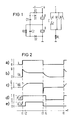
- the circuit arrangement of Figure 1 shows a first relay A and a second relay B, which are connected in series in an excitation circuit, an operating voltage + U can be connected to the excitation windings via a switch contact k.
- a diode D1 and a capacitor C1 are in series, weh A capacitor C2 and a diode D2 are connected in parallel with the winding of the relay B.
- the diodes D1 and D2 are each polarized so that when the operating voltage is applied to the series connection of the relays, the diode D1 is initially blocked, while the diode D2 is conductive.
- a resistor R1 is also connected in parallel with the diode D1, while a resistor R2 is connected in parallel with the capacitor C2.
- the contact pairs a1 and a2 of relay A are connected in series as a bridge contact in the load circuit of a load resistor RL.
- the two contact pairs b1 and b2 of relay B are also located in this load circuit parallel to the bridge contact.
- the capacitor C1 is charged via the resistor R1 during operation. If the operating voltage is now switched off, the diode D2 blocks, while the diode D1 conducts, so that the relay B drops out immediately, but the relay A only drops out after the capacitor C1 has discharged. The capacitor C2 is then discharged via the resistor R2.
- FIG. 2 shows the timing of the switching process described above over a time axis t.
- Curve a shows the state of the switch contact k (0 or 1).
- Curve b shows the curve of the excitation voltage U A at relay A, curve c the corresponding voltage curve U B at relay B.
- Curves d and e show the corresponding switching state (0 or 1) of the associated contacts a1, a2 or b1 and b2. It can be seen that at time t1, relay A with contacts a1 and a2 switches through, but relay B with contacts b1 and b2 only delays at time t2. When switching off at time t3, relay B initially drops out, causing contacts b1 and b2 to open. Only then does relay A drop out with a delay and open contacts a1 and a2 (time t4).
Landscapes
- Relay Circuits (AREA)
- Electronic Switches (AREA)
- Keying Circuit Devices (AREA)
Applications Claiming Priority (2)
| Application Number | Priority Date | Filing Date | Title |
|---|---|---|---|
| DE4022893 | 1990-07-18 | ||
| DE4022893A DE4022893C1 (fr) | 1990-07-18 | 1990-07-18 |
Publications (3)
| Publication Number | Publication Date |
|---|---|
| EP0466977A2 true EP0466977A2 (fr) | 1992-01-22 |
| EP0466977A3 EP0466977A3 (en) | 1992-11-25 |
| EP0466977B1 EP0466977B1 (fr) | 1995-07-19 |
Family
ID=6410548
Family Applications (1)
| Application Number | Title | Priority Date | Filing Date |
|---|---|---|---|
| EP90124630A Expired - Lifetime EP0466977B1 (fr) | 1990-07-18 | 1990-12-18 | Dispositif commutateur pour commuter des charges importantes |
Country Status (3)
| Country | Link |
|---|---|
| EP (1) | EP0466977B1 (fr) |
| AT (1) | ATE125391T1 (fr) |
| DE (2) | DE4022893C1 (fr) |
Families Citing this family (2)
| Publication number | Priority date | Publication date | Assignee | Title |
|---|---|---|---|---|
| FR3087957B1 (fr) * | 2018-10-31 | 2021-07-16 | Schneider Electric Ind Sas | Dispositif d'interconnexion d'appareils de coupure d'un courant electrique |
| DE102022207772A1 (de) | 2022-07-28 | 2024-02-08 | Robert Bosch Gesellschaft mit beschränkter Haftung | MEMS-Relais mit Sicherheitsfunktion |
Family Cites Families (5)
| Publication number | Priority date | Publication date | Assignee | Title |
|---|---|---|---|---|
| DE1175807B (de) * | 1959-04-10 | 1964-08-13 | Schaltbau Gmbh | Elektrische Zwillingskontaktanordnung mit zeit-lich nacheinanderschaltenden Kontaktpaaren |
| DE2808942A1 (de) * | 1978-03-02 | 1979-09-06 | Tekade Felten & Guilleaume | Schaltungsanordnung zum umschalten von relais |
| DE3310458A1 (de) * | 1983-03-23 | 1984-10-04 | Standard Elektrik Lorenz Ag, 7000 Stuttgart | Elektrische schaltvorrichtung |
| US4584621A (en) * | 1984-01-23 | 1986-04-22 | Yang Tai Her | Two or more than two poles switch means having unequal contact gaps and turn off capacities |
| GB2170654A (en) * | 1985-02-01 | 1986-08-06 | Greenwood Systems Limited | Switching arrangement |
-
1990
- 1990-07-18 DE DE4022893A patent/DE4022893C1/de not_active Expired - Fee Related
- 1990-12-18 EP EP90124630A patent/EP0466977B1/fr not_active Expired - Lifetime
- 1990-12-18 AT AT90124630T patent/ATE125391T1/de active
- 1990-12-18 DE DE59009423T patent/DE59009423D1/de not_active Expired - Fee Related
Also Published As
| Publication number | Publication date |
|---|---|
| DE59009423D1 (de) | 1995-08-24 |
| EP0466977A3 (en) | 1992-11-25 |
| DE4022893C1 (fr) | 1991-08-29 |
| EP0466977B1 (fr) | 1995-07-19 |
| ATE125391T1 (de) | 1995-08-15 |
Similar Documents
| Publication | Publication Date | Title |
|---|---|---|
| EP1228519A1 (fr) | Commutateur de securite servant a la mise sous tension et a la mise hors tension de securite d'un recepteur electrique, en particulier d'une machine a entrainement electrique | |
| DE1118858B (de) | Leistungsschalter mit Parallelkapazitaeten | |
| DE3217528C2 (de) | Kontaktanordnung für Relais | |
| DE3541338C2 (fr) | ||
| DE10051161C1 (de) | Verfahren und Vorrichtung zur Reduzierung des Kontaktabbrandes eines Schaltgerätes | |
| EP0466977B1 (fr) | Dispositif commutateur pour commuter des charges importantes | |
| DE2019184C3 (de) | Starkstromschalteinrichtung | |
| EP1307894B1 (fr) | Commutateur de securite pour la mise hors-circuit sure d'une charge electrique, en particulier d'une machine a entrainement electrique | |
| DE2060511A1 (de) | Relaissteuersystem | |
| DE3127460C2 (de) | Schaltungsanordnung für einen leistungsbegrenzten Wechselrichter | |
| DE4337665C1 (de) | Schützsicherheitskombination | |
| EP1203388A1 (fr) | Circuit de temporisation d'interruption pour un appareil de commutation electromecanique | |
| DE202014001799U1 (de) | Trafostufenschalter | |
| EP0978131A1 (fr) | Circuit pour un commutateur de reglage en charge | |
| DE973372C (de) | Relais mit Ansprechverzoegerung durch einen Kondensator, insbesondere fuer Signalanlagen | |
| DE1809862B2 (de) | Lichtbogenfreier Hochleistungsschalter | |
| DE19847812C2 (de) | Elektronisches Lastrelais | |
| DE2736521C3 (de) | Lastumschalter für Transformatoren | |
| DE2451011C2 (de) | Hochspannungs-Leistungsschalter mit Ein- und Ausschaltwiderständen | |
| DE1243267B (de) | Laststufen-Umschalter fuer Transformatoren | |
| DE2359628C3 (de) | Wender zum Umschalten der Fein- oder Grobstufenwicklung eines mit einem Stufenschalter ausgerüsteten Transformators | |
| DE3153262C2 (de) | Schaltungsanordnung zum Betrieb eines bistabilen Relais mit monostabiler Schaltcharakteristik | |
| DE3425831A1 (de) | Heizvorrichtung | |
| DE2804320C3 (de) | Lastumschalter für Transformatoren | |
| DE4228643C2 (de) | Schaltmodul |
Legal Events
| Date | Code | Title | Description |
|---|---|---|---|
| PUAI | Public reference made under article 153(3) epc to a published international application that has entered the european phase |
Free format text: ORIGINAL CODE: 0009012 |
|
| 17P | Request for examination filed |
Effective date: 19901218 |
|
| AK | Designated contracting states |
Kind code of ref document: A2 Designated state(s): AT DE FR GB IT |
|
| PUAL | Search report despatched |
Free format text: ORIGINAL CODE: 0009013 |
|
| AK | Designated contracting states |
Kind code of ref document: A3 Designated state(s): AT DE FR GB IT |
|
| 17Q | First examination report despatched |
Effective date: 19941124 |
|
| GRAA | (expected) grant |
Free format text: ORIGINAL CODE: 0009210 |
|
| AK | Designated contracting states |
Kind code of ref document: B1 Designated state(s): AT DE FR GB IT |
|
| REF | Corresponds to: |
Ref document number: 125391 Country of ref document: AT Date of ref document: 19950815 Kind code of ref document: T |
|
| REF | Corresponds to: |
Ref document number: 59009423 Country of ref document: DE Date of ref document: 19950824 |
|
| ITF | It: translation for a ep patent filed | ||
| GBT | Gb: translation of ep patent filed (gb section 77(6)(a)/1977) |
Effective date: 19950925 |
|
| ET | Fr: translation filed | ||
| PGFP | Annual fee paid to national office [announced via postgrant information from national office to epo] |
Ref country code: GB Payment date: 19951123 Year of fee payment: 6 |
|
| PGFP | Annual fee paid to national office [announced via postgrant information from national office to epo] |
Ref country code: AT Payment date: 19951129 Year of fee payment: 6 |
|
| PGFP | Annual fee paid to national office [announced via postgrant information from national office to epo] |
Ref country code: FR Payment date: 19951226 Year of fee payment: 6 |
|
| PLBE | No opposition filed within time limit |
Free format text: ORIGINAL CODE: 0009261 |
|
| STAA | Information on the status of an ep patent application or granted ep patent |
Free format text: STATUS: NO OPPOSITION FILED WITHIN TIME LIMIT |
|
| 26N | No opposition filed | ||
| PG25 | Lapsed in a contracting state [announced via postgrant information from national office to epo] |
Ref country code: DE Effective date: 19960903 |
|
| PG25 | Lapsed in a contracting state [announced via postgrant information from national office to epo] |
Ref country code: GB Effective date: 19961218 Ref country code: AT Effective date: 19961218 |
|
| GBPC | Gb: european patent ceased through non-payment of renewal fee |
Effective date: 19961218 |
|
| PG25 | Lapsed in a contracting state [announced via postgrant information from national office to epo] |
Ref country code: FR Effective date: 19970829 |
|
| REG | Reference to a national code |
Ref country code: FR Ref legal event code: ST |
|
| PG25 | Lapsed in a contracting state [announced via postgrant information from national office to epo] |
Ref country code: IT Free format text: LAPSE BECAUSE OF NON-PAYMENT OF DUE FEES;WARNING: LAPSES OF ITALIAN PATENTS WITH EFFECTIVE DATE BEFORE 2007 MAY HAVE OCCURRED AT ANY TIME BEFORE 2007. THE CORRECT EFFECTIVE DATE MAY BE DIFFERENT FROM THE ONE RECORDED. Effective date: 20051218 |