EP0467023A1 - Vorrichtung zum Räumen von verstreuten Minen - Google Patents
Vorrichtung zum Räumen von verstreuten Minen Download PDFInfo
- Publication number
- EP0467023A1 EP0467023A1 EP91106248A EP91106248A EP0467023A1 EP 0467023 A1 EP0467023 A1 EP 0467023A1 EP 91106248 A EP91106248 A EP 91106248A EP 91106248 A EP91106248 A EP 91106248A EP 0467023 A1 EP0467023 A1 EP 0467023A1
- Authority
- EP
- European Patent Office
- Prior art keywords
- pavement surface
- vehicle
- clearing
- mines
- elongate member
- Prior art date
- Legal status (The legal status is an assumption and is not a legal conclusion. Google has not performed a legal analysis and makes no representation as to the accuracy of the status listed.)
- Ceased
Links
- 230000035939 shock Effects 0.000 description 8
- 238000013016 damping Methods 0.000 description 2
- 239000002184 metal Substances 0.000 description 2
- 230000004048 modification Effects 0.000 description 2
- 238000012986 modification Methods 0.000 description 2
- 230000009528 severe injury Effects 0.000 description 2
- 238000003466 welding Methods 0.000 description 2
- 239000004698 Polyethylene Substances 0.000 description 1
- 239000006096 absorbing agent Substances 0.000 description 1
- 230000005540 biological transmission Effects 0.000 description 1
- 230000006378 damage Effects 0.000 description 1
- 238000005474 detonation Methods 0.000 description 1
- 230000009977 dual effect Effects 0.000 description 1
- 238000011065 in-situ storage Methods 0.000 description 1
- 239000000463 material Substances 0.000 description 1
- -1 polyethylene Polymers 0.000 description 1
- 229920000573 polyethylene Polymers 0.000 description 1
Images


Classifications
-
- F—MECHANICAL ENGINEERING; LIGHTING; HEATING; WEAPONS; BLASTING
- F41—WEAPONS
- F41H—ARMOUR; ARMOURED TURRETS; ARMOURED OR ARMED VEHICLES; MEANS OF ATTACK OR DEFENCE, e.g. CAMOUFLAGE, IN GENERAL
- F41H11/00—Defence installations; Defence devices
- F41H11/12—Means for clearing land minefields; Systems specially adapted for detection of landmines
- F41H11/16—Self-propelled mine-clearing vehicles; Mine-clearing devices attachable to vehicles
- F41H11/28—Self-propelled mine-clearing vehicles; Mine-clearing devices attachable to vehicles using brushing or sweeping means or dozers to push mines lying on a surface aside; using means for removing mines intact from a surface
-
- F—MECHANICAL ENGINEERING; LIGHTING; HEATING; WEAPONS; BLASTING
- F41—WEAPONS
- F41H—ARMOUR; ARMOURED TURRETS; ARMOURED OR ARMED VEHICLES; MEANS OF ATTACK OR DEFENCE, e.g. CAMOUFLAGE, IN GENERAL
- F41H11/00—Defence installations; Defence devices
- F41H11/12—Means for clearing land minefields; Systems specially adapted for detection of landmines
- F41H11/16—Self-propelled mine-clearing vehicles; Mine-clearing devices attachable to vehicles
- F41H11/20—Self-propelled mine-clearing vehicles; Mine-clearing devices attachable to vehicles with ground-penetrating elements, e.g. with means for removing buried landmines from the soil
- F41H11/24—Self-propelled mine-clearing vehicles; Mine-clearing devices attachable to vehicles with ground-penetrating elements, e.g. with means for removing buried landmines from the soil the elements being ploughs
Definitions
- the present invention relates to vehicle mountable mine clearing apparatus in general and, more particularly, to vehicle mountable apparatus for clearing a safely traversable path along a pavement surface strewn with scattered mines.
- scattered mines are generally of the variety that is activated when engaged under a relatively small force, such that it is necessary to propel them away from the pavement surface at a relatively high speed, so that when they explode they will be out of range so as not to damage the pavement or personnel or vehicles seeking to travel thereacross.
- vehicle mountable apparatus for clearing mines located on a pavement surface including one or more tensioned elongate members, mounted onto a vehicle travelling along the pavement surface in a travel direction, for engaging mines located on the pavement surface in the path of the vehicle so as to propel them away from the vehicle in a direction transverse to the travel direction, thereby clearing a safely traversable path along the pavement surface.
- mobile apparatus for clearing mines located on a pavement surface including a vehicle operative to travel across the pavement surface in a travel direction; and one or more tensioned elongate members, mounted onto the vehicle, for engaging mines located on the pavement surface in the path of the vehicle so as to propel them away from the vehicle in a direction transverse to the travel direction, thereby clearing a safely traversable path along the Pavement surface.
- vehicle mountable mine clearing apparatus including apparatus configured for mounting onto a vehicle for clearing mines buried in a mine field; and apparatus, mountable in association with the vehicle, for clearing mines located on a pavement surface.
- the apparatus for clearing mines located on a pavement surface is mounted onto the apparatus for clearing buried mines.
- the apparatus for clearing mines located on a pavement surface is operative, when the vehicle travels along the pavement surface in a travel direction, to engage mines located on the pavement surface in the path of the vehicle so as to propel them away from the vehicle in a direction transverse to the travel direction, thereby clearing a safely traversable path along the pavement surface.
- the apparatus for engaging and propelling includes one or more tensioned elongate members; and apparatus for mounting the tensioned members onto the apparatus for clearing buried mines in a position parallel to the pavement surface, at a predetermined angular orientation relative to the travel direction, and at a height relative to the pavement surface that is no lower than a predetermined height thereabove.
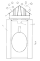
- a vehicle 10 e.g. a main battle tank, having mounted thereon apparatus, referenced generally 12, for clearing scattered mines from a pavement surface, such as a highway.
- the mine clearing apparatus 12 is mounted, via appropriate support apparatus 14, onto the front of the vehicle 10.
- a lifting system 16 for lowering apparatus 12 towards a pavement surface into a position of potential engagement with mines 18 scattered thereon, and for raising apparatus 12 when it is not in use.
- scattered mines are generally of the variety that is activated by a relatively small force, such that it is necessary to propel them away from the pavement surface at a relatively high speed, so that when they explode they will be out of range of the pavement and personnel or vehicles seeking to travel thereacross.
- Fig. 2 is a plan view illustration of a portion of the mine clearing apparatus 12, constructed according to one embodiment of the invention. It will be appreciated that the illustrated mine clearing system is symmetrical about an axis 19.
- Apparatus 12 includes a plurality of mine clearing members 20 which are arranged so as to engage scattered mines laying on a pavement surface in the path of vehicle 10, across at least the entire width of the vehicle, and to propel the mines away from the vehicle so as to clear a safely traversable path along the pavement.
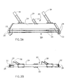
- Respective plan and front views of a single mine clearing member of the invention are shown in Figs. 3A and 3B.
- each member 20 includes a pair of mounting flanges 22 connected rigidly together via an elongate intermediate member 24.
- One or more tensioned elongate members 26 are mounted between the pair of mounting flanges 22 and are arranged such that when the mine clearing apparatus is in a lowered position, as illustrated in Fig. 5B, forward movement of the vehicle will cause engagement by an elongate member 26 of a mine laying in the path of the vehicle.
- a mine thus engaged is operative to be propelled at a velocity typically of between 20-50 km/h such that although the impact with member 26 is sufficient to activate the mine, detonation thereof will not occur within range of the travel path of the vehicle.
- elongate members 26 Although generally any suitable type of ten- sionable member may be used for elongate members 26, it has been found that 5 mm 'piano wire' attached to flanges-22 and tensioned via nuts 28 (Figs. 3A and 3B) is suitable for this purpose. In the present example, two elongate members 26 are provided, one behind the other, so as to provide a back-up member if the front member breaks during mine clearing operations.
- support apparatus 14 (Fig. 1) onto which apparatus 12 is mounted, is constituted by mine field plowing apparatus, referenced generally 30, (Fig. 2) such as described in US-A-4 467 694, whose contents are incorporated herein by reference. Only minor modifications, as described below, need be made to the plowing apparatus 30, so as to facilitate mounting thereon of mine clearing apparatus 12.
- a particular advantage of this arrangement is that a tank, for example, is thus provided with a dual mine clearing capability, both of clearing conventional fields of buried mines (after removal of apparatus 12), and by use of apparatus 12 for the clearing of scattered mines from a pavement surface.
- the mine field plowing apparatus includes right and left pluralities of plowing teeth 32, of which only the right plurality is illustrated. Skids 34, whose function is described below, are provided between the two pluralities of plowing teeth 32.
- an outside, right hand mine clearing member 20a is mounted onto plowing teeth 32, via bolted connections (not shown) between rigid, rear-facing brace members 36 and 38 (also Figs. 3A and 3B), attached to member 20a, and predetermined teeth 32.
- the length of brace members 36 and 38 is selected so as to position elongate members 26 at an optimum angle relative to the direction of travel of the vehicle, indicated by an arrow 40.
- Members 26 are preferably oriented at approximately 45° relative to the direction of travel.
- An inside right hand mine clearing member 20b is mounted onto plowing apparatus 30 via a rigid beam member 42 and an additional tooth- mounted brace member 44. Due to the more forward, overlapping position of mine clearing member 20b relative to the position of member 20a, in the present example, additional brace member 44 is longer than brace members 36 and 38.
- Beam member 42 constitutes a second support for the mine clearing member 20b and is connected at a first end 46 to the mine clearing member and at a second end 48, via a shock absorbing mount 50, to a right hand skid 34.
- Brace member 44 is connected to a plowing tooth 32 via a shock absorbing mount 51 which is generally similar to shock absorbing mount 50.
- Mount 50 is described in detail below, in conjunction with Figs. 4A-4C.
- Each mine clearing member 20 has attached thereto a wheel 29, e.g. a metal wheel, (not seen in Fig. 3B) which is mounted via an intermediate brace 33 so as to retain member 20 at a predetermined height above a travel surface when the mine clearing apparatus is in an operational position.
- a wheel 29 e.g. a metal wheel, (not seen in Fig. 3B) which is mounted via an intermediate brace 33 so as to retain member 20 at a predetermined height above a travel surface when the mine clearing apparatus is in an operational position.
- each skid 34 whose function, as described in US-A-4 467 694, is to regulate the height of an associated plow section 31 (Fig. 2) relative to a ground surface; is, in the present embodiment, fitted with a wheel 35.
- Each wheel 35 is mounted for pivoting about a generally vertical axis 39 so as to ease travel over a pavement surface that is slightly damaged.
- each wheel mounting 41 is preferably provided with a vertical damping facility, so as to reduce vertical vibrations that might otherwise be developed in the apparatus during travel.
- Wheel 35 may be any suitable type of pivot-mounted wheel with vertical damping, an example of a suitable wheel being that having catalog No. 79373 and manufactured by QUITEL, P.O.B. 28. 30 Rue Car- not, 93310, Le Pre Saint Gervais, France.
- shock absorbing mount 50 is illustrated in detail.
- Shock absorbing mount 51 is not described herein in detail as it is generally similar to mount 50.
- Mount 50 includes a pair of shock absorbing elements 52 having a rigid, typically metal outer casing 54, and an inner, resilient element 55 made, for example, of polyethylene having a hardness of typically about 95 shor.
- An example of a suitable material is marketed under the name FIBROFLEX (R).
- Elements 52 are connected, as illustrated in Fig. 4C, as by welding, to a lower plate 56 which is mounted by any suitable means onto skid 34. Elements 52 are also connected to second end 48 of beam member 42 via a pair of lugs or bolts 58 extending through lateral bores in respective resilient elements 55 and rigidly attached to side plates 60 connected to a cover plate 61 to which beam member 42 is rigidly attached as by welding.
- Shock absorbing mounts 50 and 51 are operative to prevent the transmission of significant vibrations from the mine clearing apparatus to the vehicle, when it is being used for mine clearing operations.
- Figs. 5A and 5B scattered mine clearing apparatus 12 and mine field plowing apparatus 30 are shown in raised and lowered positions respectively.
- apparatuses 12 and 30 are raised, whereas in the position depicted in Fig. 5B the apparatus has been lowered towards a pavement surface 62 so as to be used for clearing cattered mines, as described below in conjunction with Fig. 6.
- lifting apparatus 16 (Fig. 1) is constituted by apparatus such as that described in US-A-4 467 694 used for raising and lowering plowing apparatus 30 thereof.
- FIG. 6 the clearing of scattered mines 18 from pavement surface 62 is depicted schematically.
- each of the illustrated mines 18 is engaged successively by one of the tensioned elongate memhers 26 so as to be deflected sideways, as indicated by arrows 65.
- a typical deflection path of single deflected mines is shown by a series 66 of broken line circles, each mine being propelled sideways with sufficient force so as to clear edge 68 of the pavement surface 62.
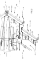
- support apparatus 14 (Fig. 1) is constituted by an arrangement of four bar systems 70 to which mine clearing members 20 (of which a single one is illustrated in the present example), are attached by appropriate connector members 71 and 73 (Fig. 7B).
- the four bar system 70 includes upper and lower, similar length, elongate members, respectively referenced 72 and 74, each of which is hingedly connected to a transverse mounting member 75 (Fig. 7A) attached to the underside 76 of the vehicle hull 78 and constituting the third element of the four bar system.
- a triangular link arrangement 80 which constitutes the fourth element of the four bar system comprises a pair of links 81 and 82 and a cross link 83. Links 81 and 82 are connected together at an apex location 84 and are further, rigidly connected together by cross link 83.
- Link arrangement 80 is connected to the elongate members 72 and 74 at respective hinge locations 82a and 82b.
- Mine clearing member 20 is rigidly mounted onto the four bar system 70 via link 81 which, according to the present embodiment is maintained continuously in an orientation at right angles to pavement surface 62 (Fig. 7A).
- Lifting apparatus 16 (Fig. 1) is constituted in the present embodiment by a lifting device 85 (Fig. 7A) mounted via a mount 86 onto an upper portion 88 of the vehicle hull 78.
- the lifting device 85 is also mounted onto an upwardly extending portion of transverse mounting member 75.
- Lifting device may be any suitable lifting apparatus, although in the present example it is an electrical winch connected to the four bar system 70 via a cable 90 attached to a hook member 92 fixed to upper elongate member 72. Operation of the winch in a first direction causes taking up of the cable so as to raise the mine clearing member 20 into the position shown by broken lines in Fig. 7A. Operation of the winch in an opposite, second direction, permits paying out of the cable and, therefore, lowering of the mine clearing member 20 under its own weight and the weight of the four bar system.
- an advantage of the present embodiment is that due to its relatively light weight (when compared with the combined system of Figs. 2 - 6) it may used in conjunction with not only tanks or other heavy armored vehicles, but, with minor modifications, it may also be used in conjunction with other vehicles such as trucks.
Landscapes
- Engineering & Computer Science (AREA)
- General Engineering & Computer Science (AREA)
- Life Sciences & Earth Sciences (AREA)
- Soil Sciences (AREA)
- Road Repair (AREA)
- Road Paving Machines (AREA)
Applications Claiming Priority (2)
| Application Number | Priority Date | Filing Date | Title |
|---|---|---|---|
| IL9503590A IL95035A (en) | 1990-07-10 | 1990-07-10 | Apparatus for clearing scattered mines |
| IL95035 | 1990-07-10 |
Publications (1)
| Publication Number | Publication Date |
|---|---|
| EP0467023A1 true EP0467023A1 (de) | 1992-01-22 |
Family
ID=11061393
Family Applications (1)
| Application Number | Title | Priority Date | Filing Date |
|---|---|---|---|
| EP91106248A Ceased EP0467023A1 (de) | 1990-07-10 | 1991-04-18 | Vorrichtung zum Räumen von verstreuten Minen |
Country Status (3)
| Country | Link |
|---|---|
| US (1) | US5105712A (de) |
| EP (1) | EP0467023A1 (de) |
| IL (1) | IL95035A (de) |
Cited By (3)
| Publication number | Priority date | Publication date | Assignee | Title |
|---|---|---|---|---|
| EP0588047A1 (de) * | 1992-09-15 | 1994-03-23 | MaK System Gesellschaft mbH | Minenräumanordnung |
| WO2003091653A3 (en) * | 2002-04-26 | 2004-03-18 | Inter Continental Safety Syste | Method and processor for removing explosive devices from an area of land |
| WO2022089857A1 (en) * | 2020-10-27 | 2022-05-05 | Pearson Engineering Limited | Improvements in or relating to mine clearance |
Families Citing this family (3)
| Publication number | Priority date | Publication date | Assignee | Title |
|---|---|---|---|---|
| US5700966A (en) * | 1994-12-27 | 1997-12-23 | Lamarra; Frank | Wireless remote channel-MIDI switching device |
| US5576507A (en) * | 1994-12-27 | 1996-11-19 | Lamarra; Frank | Wireless remote channel-MIDI switching device |
| RU2241198C1 (ru) * | 2003-04-29 | 2004-11-27 | ОАО "ФНПЦ "Станкомаш" | Машина разминирования местности |
Citations (2)
| Publication number | Priority date | Publication date | Assignee | Title |
|---|---|---|---|---|
| FR2225713A1 (de) * | 1973-04-11 | 1974-11-08 | Licentia Gmbh | |
| EP0300254A2 (de) * | 1987-07-21 | 1989-01-25 | Krauss-Maffei Aktiengesellschaft | Minenräumvorrichtung |
Family Cites Families (19)
| Publication number | Priority date | Publication date | Assignee | Title |
|---|---|---|---|---|
| US2486372A (en) * | 1944-08-12 | 1949-10-25 | Harvey W Rockwell | Detachable implement for vehicles |
| US2425357A (en) * | 1945-03-16 | 1947-08-12 | Walker Brooks | Apparatus for exploding land mines |
| FR914285A (fr) * | 1945-04-10 | 1946-10-03 | Dispositif et engins pour le déminage des terrains | |
| US2460322A (en) * | 1945-05-26 | 1949-02-01 | Walker Brooks | Mine exploder |
| US2489340A (en) * | 1946-08-06 | 1949-11-29 | Du Pont | Process of vulcanizing elastomers |
| US3771413A (en) * | 1972-05-01 | 1973-11-13 | Us Army | Mine neutralization device |
| DE2430709A1 (de) * | 1974-06-26 | 1976-01-08 | Porsche Ag | Landminen-schnellraeumgeraet |
| DE2632568A1 (de) * | 1976-07-20 | 1978-01-26 | Kaelble Gmbh C | Geraet zum raeumen von landminen |
| IL64023A0 (en) * | 1981-10-09 | 1982-01-31 | Israel Aircraft Ind Ltd | Mine-field clearing apparatus mountable on a vehicle |
| IL63437A (en) * | 1981-07-27 | 1985-03-31 | Israel Aircraft Ind Ltd | Mine-field clearing apparatus mountable on a vehicle |
| DE3271136D1 (en) * | 1981-07-27 | 1986-06-19 | Israel Aircraft Ind Ltd | Mine-field clearing apparatus mountable on a vehicle |
| DE3138590C2 (de) * | 1981-09-29 | 1986-09-25 | Thyssen Industrie Ag, 4300 Essen | Räumtiefentasteinrichtung für Landminenräumgeräte |
| IL75421A (en) * | 1982-05-19 | 1987-12-31 | Israel Aircraft Ind Ltd | Mine field clearing apparatus |
| US4690030A (en) * | 1982-12-09 | 1987-09-01 | Israel Aircraft Industries Ltd. | Mine field clearing apparatus |
| IL67437A (en) * | 1982-12-09 | 1987-12-31 | Israel Aircraft Ind Ltd | Mine-field clearing apparatus |
| IL67438A (en) * | 1982-12-09 | 1987-12-31 | Israel Aircraft Ind Ltd | Mine-field clearing apparatus |
| CA1204283A (en) * | 1983-06-03 | 1986-05-13 | Max Azulai | Mine-field clearing apparatus mountable on a vehicle |
| DE3410332A1 (de) * | 1984-03-21 | 1985-10-24 | Thyssen Industrie Ag, 4300 Essen | Vorrichtung zum raeumen von leichten landminen |
| US4938114A (en) * | 1989-10-02 | 1990-07-03 | The United States Of America As Represented By The Secretary Of The Navy | Mine clearing apparatus |
-
1990
- 1990-07-10 IL IL9503590A patent/IL95035A/en not_active IP Right Cessation
-
1991
- 1991-04-18 EP EP91106248A patent/EP0467023A1/de not_active Ceased
- 1991-04-30 US US07/694,956 patent/US5105712A/en not_active Expired - Fee Related
Patent Citations (2)
| Publication number | Priority date | Publication date | Assignee | Title |
|---|---|---|---|---|
| FR2225713A1 (de) * | 1973-04-11 | 1974-11-08 | Licentia Gmbh | |
| EP0300254A2 (de) * | 1987-07-21 | 1989-01-25 | Krauss-Maffei Aktiengesellschaft | Minenräumvorrichtung |
Cited By (6)
| Publication number | Priority date | Publication date | Assignee | Title |
|---|---|---|---|---|
| EP0588047A1 (de) * | 1992-09-15 | 1994-03-23 | MaK System Gesellschaft mbH | Minenräumanordnung |
| WO2003091653A3 (en) * | 2002-04-26 | 2004-03-18 | Inter Continental Safety Syste | Method and processor for removing explosive devices from an area of land |
| WO2022089857A1 (en) * | 2020-10-27 | 2022-05-05 | Pearson Engineering Limited | Improvements in or relating to mine clearance |
| GB2615220A (en) * | 2020-10-27 | 2023-08-02 | Pearson Eng Ltd | Improvements in or relating to mine clearance |
| GB2615220B (en) * | 2020-10-27 | 2025-01-01 | Pearson Eng Ltd | Improvements in or relating to mine clearance |
| US12228380B2 (en) | 2020-10-27 | 2025-02-18 | Pearson Engineering Limited | Mine clearance |
Also Published As
| Publication number | Publication date |
|---|---|
| US5105712A (en) | 1992-04-21 |
| IL95035A (en) | 1994-06-24 |
| IL95035A0 (en) | 1991-06-10 |
Similar Documents
| Publication | Publication Date | Title |
|---|---|---|
| US4815565A (en) | Low maintenance crash cushion end treatment | |
| EP0190510B1 (de) | Minenräumgerät | |
| US6915728B2 (en) | Mine detonating apparatus and vehicle including such apparatus | |
| US4840105A (en) | Mine field clearing apparatus | |
| US4667564A (en) | Apparatus for clearing light land mines | |
| US8397612B2 (en) | Modular roller system | |
| CA1302666C (en) | Bridgelaying vehicle with a launching assembly for bridges or bridge sections carried one on top of the other | |
| US5105712A (en) | Apparatus for clearing scattered mines | |
| US10168126B2 (en) | Roller | |
| CA3198327A1 (en) | Utilizing a suspension protector to deflect debris away from a set of suspension components of a tracked vehicle | |
| US7156591B2 (en) | High mobility recovery trailer | |
| GB2052695A (en) | A Light Reconnaissance or Patrol Vehicle | |
| US4222457A (en) | Hydraulic platforms | |
| US5906243A (en) | Countermine breaching power blade | |
| IL110479A (en) | System for mine disposal by detonation | |
| US5209002A (en) | Front-end bucket assembly for use with 4-wheel drive vehicle | |
| RU2696889C1 (ru) | Модульный минный трал сплошного траления | |
| EP0149567A2 (de) | Auffahrdämpfende Vorrichtung | |
| ES2266682T3 (es) | Vehiculo blindado de desminado con dispositivo de transporte. | |
| GB2419567A (en) | Vehicle for use in mined areas | |
| DE10018248B4 (de) | Minenräumfahrzeug | |
| US7607740B2 (en) | Wheel assembly for vehicle having drive plates in which forces exceeding a level are not transferred to the axle | |
| RU2147535C1 (ru) | Пневмогусеничное шасси и пневмогусеничный бронепоезд | |
| RU2241198C1 (ru) | Машина разминирования местности | |
| RU2794373C1 (ru) | Дополнительная защита корпуса бронированного транспортного средства (варианты) |
Legal Events
| Date | Code | Title | Description |
|---|---|---|---|
| PUAI | Public reference made under article 153(3) epc to a published international application that has entered the european phase |
Free format text: ORIGINAL CODE: 0009012 |
|
| AK | Designated contracting states |
Kind code of ref document: A1 Designated state(s): AT BE CH DE DK ES FR GB GR IT LI LU NL SE |
|
| 17P | Request for examination filed |
Effective date: 19920722 |
|
| 17Q | First examination report despatched |
Effective date: 19940506 |
|
| GRAG | Despatch of communication of intention to grant |
Free format text: ORIGINAL CODE: EPIDOS AGRA |
|
| STAA | Information on the status of an ep patent application or granted ep patent |
Free format text: STATUS: THE APPLICATION HAS BEEN REFUSED |
|
| 18R | Application refused |
Effective date: 19961018 |