EP0467047A2 - Fenster und sein Rahmen - Google Patents
Fenster und sein Rahmen Download PDFInfo
- Publication number
- EP0467047A2 EP0467047A2 EP91108434A EP91108434A EP0467047A2 EP 0467047 A2 EP0467047 A2 EP 0467047A2 EP 91108434 A EP91108434 A EP 91108434A EP 91108434 A EP91108434 A EP 91108434A EP 0467047 A2 EP0467047 A2 EP 0467047A2
- Authority
- EP
- European Patent Office
- Prior art keywords
- frame
- window
- window structure
- interspacing
- glazing unit
- Prior art date
- Legal status (The legal status is an assumption and is not a legal conclusion. Google has not performed a legal analysis and makes no representation as to the accuracy of the status listed.)
- Withdrawn
Links
Images


Classifications
-
- E—FIXED CONSTRUCTIONS
- E06—DOORS, WINDOWS, SHUTTERS, OR ROLLER BLINDS IN GENERAL; LADDERS
- E06B—FIXED OR MOVABLE CLOSURES FOR OPENINGS IN BUILDINGS, VEHICLES, FENCES OR LIKE ENCLOSURES IN GENERAL, e.g. DOORS, WINDOWS, BLINDS, GATES
- E06B3/00—Window sashes, door leaves, or like elements for closing wall or like openings; Layout of fixed or moving closures, e.g. windows in wall or like openings; Features of rigidly-mounted outer frames relating to the mounting of wing frames
- E06B3/04—Wing frames not characterised by the manner of movement
- E06B3/26—Compound frames, i.e. one frame within or behind another
- E06B3/2605—Compound frames, i.e. one frame within or behind another with frames permanently mounted behind or within each other, each provided with a pane or screen
-
- E—FIXED CONSTRUCTIONS
- E06—DOORS, WINDOWS, SHUTTERS, OR ROLLER BLINDS IN GENERAL; LADDERS
- E06B—FIXED OR MOVABLE CLOSURES FOR OPENINGS IN BUILDINGS, VEHICLES, FENCES OR LIKE ENCLOSURES IN GENERAL, e.g. DOORS, WINDOWS, BLINDS, GATES
- E06B3/00—Window sashes, door leaves, or like elements for closing wall or like openings; Layout of fixed or moving closures, e.g. windows in wall or like openings; Features of rigidly-mounted outer frames relating to the mounting of wing frames
- E06B3/30—Coverings, e.g. protecting against weather, for decorative purposes
- E06B3/301—Coverings, e.g. protecting against weather, for decorative purposes consisting of prefabricated profiled members or glass
- E06B3/306—Covering plastic frames with metal or plastic profiled members
-
- E—FIXED CONSTRUCTIONS
- E06—DOORS, WINDOWS, SHUTTERS, OR ROLLER BLINDS IN GENERAL; LADDERS
- E06B—FIXED OR MOVABLE CLOSURES FOR OPENINGS IN BUILDINGS, VEHICLES, FENCES OR LIKE ENCLOSURES IN GENERAL, e.g. DOORS, WINDOWS, BLINDS, GATES
- E06B3/00—Window sashes, door leaves, or like elements for closing wall or like openings; Layout of fixed or moving closures, e.g. windows in wall or like openings; Features of rigidly-mounted outer frames relating to the mounting of wing frames
- E06B3/54—Fixing of glass panes or like plates
- E06B3/58—Fixing of glass panes or like plates by means of borders, cleats, or the like
- E06B3/585—Fixing of glass panes or like plates by means of borders, cleats, or the like adjustable, e.g. for accommodating panes of various thickness, or with provisions for altering the clamping force on the pane
-
- E—FIXED CONSTRUCTIONS
- E06—DOORS, WINDOWS, SHUTTERS, OR ROLLER BLINDS IN GENERAL; LADDERS
- E06B—FIXED OR MOVABLE CLOSURES FOR OPENINGS IN BUILDINGS, VEHICLES, FENCES OR LIKE ENCLOSURES IN GENERAL, e.g. DOORS, WINDOWS, BLINDS, GATES
- E06B3/00—Window sashes, door leaves, or like elements for closing wall or like openings; Layout of fixed or moving closures, e.g. windows in wall or like openings; Features of rigidly-mounted outer frames relating to the mounting of wing frames
- E06B3/54—Fixing of glass panes or like plates
- E06B3/58—Fixing of glass panes or like plates by means of borders, cleats, or the like
- E06B3/5892—Fixing of window panes in openings in door leaves
-
- E—FIXED CONSTRUCTIONS
- E06—DOORS, WINDOWS, SHUTTERS, OR ROLLER BLINDS IN GENERAL; LADDERS
- E06B—FIXED OR MOVABLE CLOSURES FOR OPENINGS IN BUILDINGS, VEHICLES, FENCES OR LIKE ENCLOSURES IN GENERAL, e.g. DOORS, WINDOWS, BLINDS, GATES
- E06B3/00—Window sashes, door leaves, or like elements for closing wall or like openings; Layout of fixed or moving closures, e.g. windows in wall or like openings; Features of rigidly-mounted outer frames relating to the mounting of wing frames
- E06B3/54—Fixing of glass panes or like plates
- E06B3/64—Fixing of more than one pane to a frame
-
- E—FIXED CONSTRUCTIONS
- E06—DOORS, WINDOWS, SHUTTERS, OR ROLLER BLINDS IN GENERAL; LADDERS
- E06B—FIXED OR MOVABLE CLOSURES FOR OPENINGS IN BUILDINGS, VEHICLES, FENCES OR LIKE ENCLOSURES IN GENERAL, e.g. DOORS, WINDOWS, BLINDS, GATES
- E06B3/00—Window sashes, door leaves, or like elements for closing wall or like openings; Layout of fixed or moving closures, e.g. windows in wall or like openings; Features of rigidly-mounted outer frames relating to the mounting of wing frames
- E06B3/66—Units comprising two or more parallel glass or like panes permanently secured together
- E06B3/663—Elements for spacing panes
- E06B3/66309—Section members positioned at the edges of the glazing unit
- E06B3/66342—Section members positioned at the edges of the glazing unit characterised by their sealed connection to the panes
- E06B3/66347—Section members positioned at the edges of the glazing unit characterised by their sealed connection to the panes with integral grooves or rabbets for holding the panes
-
- E—FIXED CONSTRUCTIONS
- E06—DOORS, WINDOWS, SHUTTERS, OR ROLLER BLINDS IN GENERAL; LADDERS
- E06B—FIXED OR MOVABLE CLOSURES FOR OPENINGS IN BUILDINGS, VEHICLES, FENCES OR LIKE ENCLOSURES IN GENERAL, e.g. DOORS, WINDOWS, BLINDS, GATES
- E06B3/00—Window sashes, door leaves, or like elements for closing wall or like openings; Layout of fixed or moving closures, e.g. windows in wall or like openings; Features of rigidly-mounted outer frames relating to the mounting of wing frames
- E06B3/04—Wing frames not characterised by the manner of movement
- E06B3/26—Compound frames, i.e. one frame within or behind another
- E06B3/2605—Compound frames, i.e. one frame within or behind another with frames permanently mounted behind or within each other, each provided with a pane or screen
- E06B2003/2615—Frames made of metal
-
- E—FIXED CONSTRUCTIONS
- E06—DOORS, WINDOWS, SHUTTERS, OR ROLLER BLINDS IN GENERAL; LADDERS
- E06B—FIXED OR MOVABLE CLOSURES FOR OPENINGS IN BUILDINGS, VEHICLES, FENCES OR LIKE ENCLOSURES IN GENERAL, e.g. DOORS, WINDOWS, BLINDS, GATES
- E06B3/00—Window sashes, door leaves, or like elements for closing wall or like openings; Layout of fixed or moving closures, e.g. windows in wall or like openings; Features of rigidly-mounted outer frames relating to the mounting of wing frames
- E06B3/66—Units comprising two or more parallel glass or like panes permanently secured together
- E06B3/663—Elements for spacing panes
- E06B3/66309—Section members positioned at the edges of the glazing unit
- E06B2003/66395—U-shape
Definitions
- the present invention relates to windows and to window structures of the type in which the frame is composed of two frame sections adapted to be secured to opposite faces of an opening made in doors or the like.
- This invention defines a window for a door or the like including a glazing unit and a window frame for holding said unit and formed of two frame sections, each adjustably interconnected by clips to allow readily adjustment of the frame to different thicknesses of doors while maintaining the glazing unit centrally of the door thickness.
- the clips in the assembled structure can be readily disengaged from the frame sections to conveniently replace or repair the glazing panes.
- the clip it has an H-shape with oppositely directed clip structures.
- each frame section can be molded in one piece; alternately each frame section is assembled from extruded straight side members which define inner spaces opening at the ends of the side members for receiving with a friction shift angle connectors rendering the joints weatherproof.
- Window pane retaining clips are also provided to press a window pane against each frame section.
- An interspacing frame for a double pane glazing unit is also provided. This frame not only keeps the panes apart but includes ribs to properly locate the panes, grooves on the opposite sides for sealing strips and a channel for desiccant material.
- the desiccant can be contained in a separate perforated tube adhered to the interspacing frame.
- FIG. 1 there is illustrated a brick wall 10 in which a garage door 11 and an ordinary door 12 are installed. These doors may be of any conventional construction, the details of which do not form part of the present invention.
- the garage door 11 includes a pair of windows 13 and the door 12 includes a similar window, all of which are constructed and installed in the corresponding door according to the present invention.
- the illustrated window 13 includes a glazing unit of the double pane type; however, a window frame according to the present invention may also be provided to hold a glazing unit having a single window pane, as will be better understood later.
- the window 13 comprises a window frame including frame sections 14 and 15 which are in fact of identical construction and each molded in one piece. However the frame sections can be assembled from four separate parts as will be described hereinafter with respect to Figures 17 to 26.
- Each of the two frame sections is integrally molded in one-piece and includes a main peripheral portion 18 and a rim portion 22, both extending along the full periphery of the window frame and normal to each other.
- Each frame section is further formed with lateral projections 16, 17, which are parallel to portion 18.
- a pair of grooves 19 and 20, each of which longitudinally extends along the full periphery of the frame are defined between projections 16 and 17 and between projections 17 and peripheral portion 18, respectively.
- a resilient foam material 21 fills groove 19 and inwardly projects from it, as best seen in Figure 2.
- Rim 22 outwardly projects from peripheral portion 22 and has a flat inside face adapted to rest flat against the corresponding face of the door 11.
- An interspacing frame 23, molded in one piece, is constructed and arranged to space apart the two window panes 24 and to operatively constitute with them a sealed double pane glazing unit.
- the interspacing frame 23 is integrally molded to form an outer peripheral face, an inner peripheral face and a pair of parallel and opposite lateral faces. All of these faces longitudinally extend co-extensive with the full periphery of frame 23.
- Continuous ribs 25 extend along the longer and shorter sides of frame 23 at the edges of the outer peripheral face. The ribs 25 project from the opposite lateral faces of the interspacing frame and serve to locate and restrain the window panes 24 within the peripheral outline of frame 23 during assembly of the double pane glazing unit.
- Frame 23 ( Figure 5) is formed with a groove 26 in each of its two opposite lateral faces and with a channel 27, all longitudinally extending along the full periphery of the interspacing frame. However, the channel 27 may extend along as little as only on one side of the frame. There are thus formed a longitudinal projection 28 that laterally projects short of the window panes 24 to leave a peripheral gap 28A along the same.
- An air seal strip 29 (for instance silicone adhesive) is placed in each peripheral groove 26 and projects from the corresponding lateral face to sealingly engage against the full perimeter of the corresponding window pane and hold the latter to frame 23.
- a desiccant 30 fills the channel 27 inward of the air seal strips 29 and communicates with the sealed space between the window pane through the afore-mentioned gap 28A between the projection 28 and the corresponding window pane.
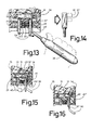
- H-shape clips 31, shown in more details in Figure 3, serve to interconnect the two frame sections 14, 15 with an adjustable spacing. They are provided at spaced-apart locations around the window frame outward of the sheets of glass 24.
- Each clip 31 includes two aligned inner legs 32 and two aligned outer legs 33. The four legs are interconnected by a central web 31 A. On each side of web 31A, the two spaced parallel legs 32, 33 form a pair of legs adapted to receive lateral projection 18 therebetween. The end of one leg 32 can be extended if desired, by a transverse tab 32'.
- the inside faces of outer legs 33 are formed with ratchet teeth 35 which are inclined towards web 31A.
- Clips 31 extend transversely of the window frame with outer legs 23 disposed outwardly with respect to the center of the window unit. At each end of each clip 31, the two inner legs 32 extend outward of the corresponding outer peripheral face of interspacing frame 23 and inward of the corresponding projection 18. Inner legs 32 are in sliding contact with the inner face of projection 18 of the respective frame sections 14, 15. The projection 18 terminates into an outwardly-directed pawl tooth 34 on at least two opposite sides of each frame section 14, 15, as best seen in Figure 7. Each pawl tooth 34 extends longitudinally of most of the length of the corresponding side of the frame sections 14, 15 but terminates short of the frame portion corner to leave a gap 34a. Each projection 18 is inserted between legs 32 and 33 at the corresponding end of clip 31 and pawl tooth 34 engages into the notch between a selected pair of ratchet teeth 35.
- the sealed double pane unit is first assembled with the window panes 24 fitting inside the boundary defined by the ribs 25 and applied against the air seal strips 29 on the opposite sides of the interspacing frame 23.
- Channel 27 is filled with desiccant 30 before adhering the second window pane 24 on top of horizontally-supported frame 23.
- This unit and one frame section 14 or 15 with clips 31 already installed thereon exteriorly of frame 23, are then positioned in an aperture of a door.
- the projection 18 of the other frame section 15 or 14 is then made to register with clips 31 and enter between clip legs 32, 33. Tabs 32' facilitate this operation.
- the two frame sections are pushed toward each other, such that the pawl teeth 34 will engage as far as possible between clip legs 32, 33 and grip a corresponding ratchet tooth 35 to adjust the spacing between the two frame sections 14, 15 in relation with the thickness of the door 11.
- the two frame sections 14, 15 are therefore retained by clips 31, with their rim portions 22 pressed against door 11.
- the one frame section adapted to be located on the outside of the door 11, (frame section 14 in Figure 2) is provided with a weather- proofing seal 14A.
- the window frame can be installed on doors of different thicknesses provided one chooses a glazing unit having a thickness proportional to the door thickness. However it should be noted that the system can also accommodate glazing units of varying thicknesses within certain limits due to the compressibility of foam strips 21. The system also maintains the glazing unit centrally of the door thickness.
- the two frame sections 40 are formed with only the projections 16 and 18 without an intermediate projection 17.
- the interspace or channel between each pair of projections 16 and 18 of the internal frame portion houses springs 41 or 42 and a floating U-shaped strip 45 which replace the resilient foam 21 and serve the same purpose to bias the window and frame structures, such that the double-pane glazing unit 24, 23, 24 can have a variable thickness and is prevented from rattling in the window frame.
- Z-shaped spring 42 of Figure 9 preferably has an inturned edge 42' to facilitate insertion of tool blade 37, as shown in Figure 16.
- corner 45' of strip 45 ( Figures 8 and 9) and corner 21' of foam 21 are rounded to facilitate tool blade insertion.
- the latter as shown at 23' in Figure 9 is not formed with the channel 27 for the desiccant 30.
- the channel is a separate tube 43 ( Figures 9 and 10), which extends longitudinally along the inner peripheral face of the interspacing frame.
- the tube 43 is provided with apertures 44 communicating the desiccant 30 filling the tube 43 with the space confined by the interspacing frame between the sheets of glass 24.
- Tube 43 is either adhered against the inner face of frame 23' or simply frictionally inserted within an inner channel of frame 23', as shown in Figure 9, just before adhering the last glass pane to interspacing frame 23'.
- Tube 43 is straight, is closed at one end and has a closure cap at its other end.
- one frame section 40 with its resilient foam strip 21 is like the one in Figure 9, together with the seal 14a. Also clips 31 and double-pane glazing unit 24, 28', 24 with desiccant tube 43 are the same.
- Frame section 40a is molded in one piece and includes lateral projections 17', 18' and rim 22' corresponding to the like projections 17, 18 and 22 of frame section 15 of Figure 2. Lateral projections 17' and 18' are just sufficiently spaced apart to receive with a sliding fit inner leg 32. A flange 46 extends from portion 17' and abuts flat against glass pane 24, thus avoiding the necessity of providing a strip of polystyrene foam such as strip 21, on the inner side of the window.
- continuous pawl teeth 34 of frame section 40a ( Figures 2 and 7) is replaced by a plurality of pawl teeth 34' spaced from one another to leave gaps 34A'.
- clips 31 are aligned with pawl teeth 34' during installation and need to be laterally displaced just a short distance to register with a gap 34A' to release the inner frame section 40a.
- the frame section 40 could be made similar to frame section 40a so as to eliminate the strip 21 of polystyrene foam shown in Figure 11 with a flange 46 directly abutting against the outer window pane 24.
- FIGS 17 to 26 show embodiments of frame sections which are assembled from four extruded straight side members. These figures also show different embodiments of the glazing unit.
- each frame section 52 is composed of four extruded straight side members 54 which are assembled together as will be later described in relation to figures 22 to 26.
- the inner and outer frame sections are of identical construction.
- Each side comprises an inner portion 56 adapted to overlap a window pane 58, a transverse peripheral portion 60 and a rim portion 62 actually extending from peripheral portion 60.
- the outer face of the latter has its inner edge formed with a continuous pawl tooth 64 protruding outwardly of peripheral portion 60.
- Rim portion 62 and inner portion 56 are of doubled wall construction, defining a narrower inner space section 68 in the rim portion 62 and a wider inner space section 70 in the inner portion 56.
- the two window panes 58 are not provided with an interspacing frame such as interspacing frame 23 or 23' shown in the previous embodiments.
- Each pane 58 is retained and pressed against the inside face of its associated frame section 52 by means of a plurality of pane retaining clips 76 as shown in figure 18 and 21.
- Each clip 76 is L-shaped and defines a pane engaging tab 78 and a pair of spaced parallel legs 80-82 which are normal to tab 78.
- the legs 80-82 are adapted to receive peripheral portion 60 between themselves.
- the outer leg 82 is provided with a series of inwardly directed ratchet teeth 84, adapted to selectively engage the pawl tooth 64 of peripheral portion 60 so that the tab 78 will adjustably press the window pane 58 against the frame section 52 in accordance with the thickness of said window pane.
- each frame section 52 is provided at its portion 56 with a groove 86, to receive sealant 88 which adheres to the external face of the window pane 58.
- the external face of each frame section 52 is provided with a pair of spaced parallel lips 90 protruding therefrom and adapted to abut against and form a finish for the longitudinal edges of a decorative strip 92 which may be a colored strip and the latter is normally adhered to the frame section 52 by adhesive 94.
- the side members 54 are cut to the desired length and to the required angle; in the case of a square or rectangular frame, the angle is obviously 45 degrees, as shown in figure 24.
- the properly cut side members 54 are then assembled by means of the two connector members shown in figures 22 and 23 or the two connector members shown in figure 26, one of them being that of figure 22.
- the connector member of figure 22 simply consists of an angular element 96, the two legs of which are at right angles to each other or at an angle corresponding to the corner of the window frame if the latter has a polygonal shape other than square or rectangular.
- the respective legs of the anlge connector 96 frictionally engage within the rectangular inner space 72 of the two side members 54, as shown in figures 25 and 26.
- the side member connector shown at 98 in figure 23, comprises an arrow-shaped flat plate 100 defining a V-shaped pointed outer end 102 and a V-shaped recessed inner end 104.
- Connector 98 further includes a pair of flanges 106 projecting from one side of flat plate 100 and normal to said plate, and each extends along an edge of the recessed inner end 104.
- a second embodiment of this connector is shown at 98a in figure 26 which has two pairs of flanges 108, 108a instead of a single pair of flanges 106.
- the flanges 108a of each pair are spaced an amount about equal to the height of the wider space section 70.
- each flange 106 is adapted to the inserted within the wider space section 70 to frictionally engage the inner wall thereof (figure 25), while in the case of connector 98a, the inner flanges 108 are engaged as above described while the outer flanges 108a also engage the respective wider space sections 70 and are in frictional contact with the outer wall of the wider space section 70 (figure 25a).
- Supposing the connector is divided in half by a line extending through the apices of the outer end 102 and inner end 104, then half the connector is inserted within the inner spaces of one frame section while the other half is inserted within the spaces of the other adjacent frame section 52.
- the pointed outer end 102 is directed towards the outer corner of the window frame as shown in figure 24 while the recessed inner end 104 fits the inner corner of the frame.
- the flat plate 104 frictionally engages the narrower space section 68 while flanges 106 or 108, 108a, as previously described frictionally engage with the corresponding walls of the wider space section 70.
- frame sections 14, 15 shown in figure 2 or 40, 40a shown in figures 8, 9 and 12 could also be made of extruded, straight side members assembled by means of connectors 96 and 98 or 98a.
- Figures 19 and 20 show a modified form of a side member designed to make frame sections adapted to support a single window pane 58a, each side member 54a being extruded in one piece.
- Its rim portion 62a is of double wall construction so as to form a narrow space section 68a, adapted to frictionally receive a modified connector consisting only of a flat angle plate 100a (figure 23a) arranged to assemble two contiguous side members 54a in the same manner as previously described.
- side member 54a has a generally rectangular inner space 72a to frictionally receive the legs of the angle connector 96.
- Each side member 54a is provided with a peripheral portion 60a with a pawl tooth 64a adapted to engage the H-shaped clip 31 as in previous embodiments.
- the inner portion 56a is inwardly inclined and is provided with a groove 86a to receive a sealant 88a for sealing pane 58a and sealing the same to the two frame sections 54a.
- FIGS 27 to 29 show another embodiment of the clip means for interconnecting the two frame sections.
- the H-shaped double clip 31 of Figures 2 or 3 is replaced by a clip structure 110 including a web 112 joining an inner leg 114 and an outer leg 116, the latter having ratchet teeth 118 for selectively engaging the pawl tooth 34b of the peripheral portion 18a of a one piece molded frame section 14a which is adapted to be positioned on the outside of door 11.
- a nut 120 is frictionally retained in a cavity 121 of web 112 in register with a bolt hole 121 a and a bolt 122 is screwed in nut 120.
- Bolt 122 is inserted into a hole of the other frame section 15a which is disposed inside door 11. By screwing bolt 122 into nut 120 the two frame sections are pressed against the opposite faces of door 11.
- the two frame sections 14a, 15a are identical.
- Several clip structures 110 are clipped around inner frame section 14a and means can be provided to locate clip structures 110 longitudinally of peripheral portion 18a to register each nut 120 with a bolt 122.
- Such means are preferably formed by a recess 124 made in peripheral portion 18a in register with pawl tooth 34b.
- Recess 124 can be used only when the frame section is molded in one piece and not when it is assembled from extruded sides. In the latter case the clip structure 110 is positioned and frictionally retained at the proper place.
Landscapes
- Engineering & Computer Science (AREA)
- Civil Engineering (AREA)
- Structural Engineering (AREA)
- Securing Of Glass Panes Or The Like (AREA)
Applications Claiming Priority (2)
| Application Number | Priority Date | Filing Date | Title |
|---|---|---|---|
| US52819590A | 1990-05-14 | 1990-05-14 | |
| US528195 | 1990-05-24 |
Publications (2)
| Publication Number | Publication Date |
|---|---|
| EP0467047A2 true EP0467047A2 (de) | 1992-01-22 |
| EP0467047A3 EP0467047A3 (en) | 1992-04-22 |
Family
ID=24104634
Family Applications (1)
| Application Number | Title | Priority Date | Filing Date |
|---|---|---|---|
| EP19910108434 Withdrawn EP0467047A3 (en) | 1990-05-14 | 1991-05-23 | Window and frame structure therefor |
Country Status (1)
| Country | Link |
|---|---|
| EP (1) | EP0467047A3 (de) |
Cited By (5)
| Publication number | Priority date | Publication date | Assignee | Title |
|---|---|---|---|---|
| FR2695689A1 (fr) * | 1992-09-14 | 1994-03-18 | Radojewski Joel | Système double clips pour parcloser un remplissage variable sur divers supports de toute nature. |
| GB2318378A (en) * | 1996-10-02 | 1998-04-22 | Door Panels Plc | Fixing profiled mouldings to skinned doors |
| US9506247B2 (en) | 2014-03-28 | 2016-11-29 | Steelcase Inc. | Transparent panel system for partitions |
| GB2563850A (en) * | 2017-06-27 | 2019-01-02 | Auto Plas Int Ltd | Mounting assembly, door, kit and method of installation |
| US10329759B2 (en) | 2012-09-17 | 2019-06-25 | Steelcase Inc. | Floor-to-ceiling partition wall assembly |
Family Cites Families (7)
| Publication number | Priority date | Publication date | Assignee | Title |
|---|---|---|---|---|
| CH488921A (de) * | 1968-03-26 | 1970-04-15 | Koller Metallbau Ag | Zur Herstellung einer Scheibenfassung dienender Rahmenschenkel |
| US3750358A (en) * | 1971-09-09 | 1973-08-07 | Rimar Mfg Inc | Self locking door light molding |
| US3918231A (en) * | 1972-02-15 | 1975-11-11 | Gerald Kessler | Frost resistant window sash |
| DE2334802A1 (de) * | 1973-07-09 | 1975-01-30 | Alco Bauzubehoer | Halteeinrichtung fuer die scheiben bei druckverglasung an fenstern oder tueren aus metall, holz oder kunststoff |
| FR2442947A1 (fr) * | 1978-11-30 | 1980-06-27 | Midi Moulages Plast | Hublot prefabrique demontable |
| CA1214962A (fr) * | 1984-03-12 | 1986-12-09 | Jean-Claude Lafleur | Chassis pour fenetre etanche |
| US4920718A (en) * | 1988-03-17 | 1990-05-01 | Odl, Incorporated | Integral door light and related door construction |
-
1991
- 1991-05-23 EP EP19910108434 patent/EP0467047A3/en not_active Withdrawn
Cited By (5)
| Publication number | Priority date | Publication date | Assignee | Title |
|---|---|---|---|---|
| FR2695689A1 (fr) * | 1992-09-14 | 1994-03-18 | Radojewski Joel | Système double clips pour parcloser un remplissage variable sur divers supports de toute nature. |
| GB2318378A (en) * | 1996-10-02 | 1998-04-22 | Door Panels Plc | Fixing profiled mouldings to skinned doors |
| US10329759B2 (en) | 2012-09-17 | 2019-06-25 | Steelcase Inc. | Floor-to-ceiling partition wall assembly |
| US9506247B2 (en) | 2014-03-28 | 2016-11-29 | Steelcase Inc. | Transparent panel system for partitions |
| GB2563850A (en) * | 2017-06-27 | 2019-01-02 | Auto Plas Int Ltd | Mounting assembly, door, kit and method of installation |
Also Published As
| Publication number | Publication date |
|---|---|
| EP0467047A3 (en) | 1992-04-22 |
Similar Documents
| Publication | Publication Date | Title |
|---|---|---|
| US5189862A (en) | Window and frame structure therefor | |
| US4341255A (en) | Storm window | |
| US5107655A (en) | Profiled section for door-leaves | |
| US3016993A (en) | Building framing unit | |
| US5090168A (en) | Extruded window frame system | |
| US4351137A (en) | Plastic panel mounting frame | |
| US4286716A (en) | Building kit for vertical or horizontal sliding windows | |
| US5369922A (en) | Window frame assembly | |
| US4682451A (en) | Protective cover for window sills | |
| US3694984A (en) | Mounting of sealed double glazing units | |
| US20050235586A1 (en) | Clip and sash assembly for mounting components between glazing panes | |
| US4250673A (en) | Window replacement system | |
| US4320609A (en) | Glazing fastener for mounting either rigid or flexible storm windows | |
| US4115973A (en) | Building structure | |
| US4164830A (en) | Double-glazed doors or windows and frame assemblies therefor | |
| US4799332A (en) | Sliding window | |
| GB2295185A (en) | Fixing frames into apertures in cavity walls | |
| US7114299B2 (en) | Glass block frame | |
| EP0466786B1 (de) | Fenster zum einbau in einer öffnung in einer sandwichwand | |
| EP0004459B1 (de) | Verbesserte Verbindungsmittel für Platten | |
| EP0467047A2 (de) | Fenster und sein Rahmen | |
| EP1798363A2 (de) | Tragendes Profil für einen Fensterrahmen | |
| GB2194328A (en) | Ventilator for door or window frames | |
| GB2157336A (en) | Partitions | |
| IE61670B1 (en) | A panel assembly |
Legal Events
| Date | Code | Title | Description |
|---|---|---|---|
| PUAI | Public reference made under article 153(3) epc to a published international application that has entered the european phase |
Free format text: ORIGINAL CODE: 0009012 |
|
| AK | Designated contracting states |
Kind code of ref document: A2 Designated state(s): DE FR GB SE |
|
| PUAL | Search report despatched |
Free format text: ORIGINAL CODE: 0009013 |
|
| AK | Designated contracting states |
Kind code of ref document: A3 Designated state(s): DE FR GB SE |
|
| 17P | Request for examination filed |
Effective date: 19921020 |
|
| 17Q | First examination report despatched |
Effective date: 19930223 |
|
| STAA | Information on the status of an ep patent application or granted ep patent |
Free format text: STATUS: THE APPLICATION IS DEEMED TO BE WITHDRAWN |
|
| 18D | Application deemed to be withdrawn |
Effective date: 19931201 |