EP0467151A1 - Véhicule pourvu d'une commande électrique dont les composants dégagent de la chaleur - Google Patents
Véhicule pourvu d'une commande électrique dont les composants dégagent de la chaleur Download PDFInfo
- Publication number
- EP0467151A1 EP0467151A1 EP91111035A EP91111035A EP0467151A1 EP 0467151 A1 EP0467151 A1 EP 0467151A1 EP 91111035 A EP91111035 A EP 91111035A EP 91111035 A EP91111035 A EP 91111035A EP 0467151 A1 EP0467151 A1 EP 0467151A1
- Authority
- EP
- European Patent Office
- Prior art keywords
- motor vehicle
- heat
- housing
- components
- vehicle according
- Prior art date
- Legal status (The legal status is an assumption and is not a legal conclusion. Google has not performed a legal analysis and makes no representation as to the accuracy of the status listed.)
- Granted
Links
Images
Classifications
-
- H—ELECTRICITY
- H05—ELECTRIC TECHNIQUES NOT OTHERWISE PROVIDED FOR
- H05K—PRINTED CIRCUITS; CASINGS OR CONSTRUCTIONAL DETAILS OF ELECTRIC APPARATUS; MANUFACTURE OF ASSEMBLAGES OF ELECTRICAL COMPONENTS
- H05K7/00—Constructional details common to different types of electric apparatus
- H05K7/20—Modifications to facilitate cooling, ventilating, or heating
- H05K7/2089—Modifications to facilitate cooling, ventilating, or heating for power electronics, e.g. for inverters for controlling motor
- H05K7/20909—Forced ventilation, e.g. on heat dissipaters coupled to components
- H05K7/20918—Forced ventilation, e.g. on heat dissipaters coupled to components the components being isolated from air flow, e.g. hollow heat sinks, wind tunnels or funnels
-
- B—PERFORMING OPERATIONS; TRANSPORTING
- B60—VEHICLES IN GENERAL
- B60H—ARRANGEMENTS OF HEATING, COOLING, VENTILATING OR OTHER AIR-TREATING DEVICES SPECIALLY ADAPTED FOR PASSENGER OR GOODS SPACES OF VEHICLES
- B60H1/00—Heating, cooling or ventilating devices
- B60H1/00507—Details, e.g. mounting arrangements, desaeration devices
- B60H1/00514—Details of air conditioning housings
-
- B—PERFORMING OPERATIONS; TRANSPORTING
- B60—VEHICLES IN GENERAL
- B60H—ARRANGEMENTS OF HEATING, COOLING, VENTILATING OR OTHER AIR-TREATING DEVICES SPECIALLY ADAPTED FOR PASSENGER OR GOODS SPACES OF VEHICLES
- B60H1/00—Heating, cooling or ventilating devices
- B60H1/00507—Details, e.g. mounting arrangements, desaeration devices
- B60H2001/00614—Cooling of electronic units in air stream
Definitions
- the invention relates to a motor vehicle with an electrical control system with heat-emitting components.
- Such motor vehicles can have, for example, an electric traction drive, which is controlled with the aid of power semiconductors.
- Electric travel drives are known both for electric road vehicles (cars, vans, buses) and for in-house transport vehicles.
- electric industrial trucks are generally equipped with electronic thyristor or transistor controls for controlling driving, hydraulic and power steering motors.
- the power loss converted into heat in these semiconductor components must be dissipated to the environment.
- the heat-generating power semiconductors are usually mounted on heat sinks which have fins and are cooled by the ambient air. If the space allows, the heat sinks can be mounted directly on massive frame parts, so that sufficient heat dissipation is guaranteed.
- a cooling device Because of the high expenditure of a cooling device, such a device is therefore preferably only used when the use of the vehicle makes this necessary.
- two vehicle types are required, namely a vehicle with fan cooling and a vehicle without fan cooling of the control system. It is therefore easy to see that the vehicle manufacturer will endeavor to provide a basic version that can be easily retrofitted with the blower.
- the cost of the basic version of the vehicle should be influenced as little as possible by the parts to be provided for the fan attachment, but this is very difficult in practice.
- the object of the present invention is to provide, using simple means, a motor vehicle of the type mentioned at the outset which has both a water and dust-protected control and also enables the control to be easily retrofitted with a cooling fan.
- This object is achieved in that the components are arranged protected from water and dust in a closed housing which is in flat contact with at least one heat-emitting outside with a part of the motor vehicle suitable for heat absorption.
- the idea, which is essential to the invention is to encapsulate the heat-emitting power semiconductors, which form an essential part of the control, from the environment in a water and dust-tight housing and to connect this housing to a suitable part of the motor vehicle for the purpose of heat dissipation, where appropriate a Heat dissipation can be increased by cooling the part in question and / or the housing by means of a blower which acts on the parts mentioned with cooling air from the outside.
- the ventilation equipment can be easily added without having to remove the complete encapsulation.
- the air flow is guided over an outer cooling surface of the control and / or the part on which the control is fastened, so that no dirt can penetrate into the control and filtering of the cooling air is unnecessary.
- the contact surface is interrupted by at least one air duct between the outside of the housing and the motor vehicle and that a fan can be connected to the air duct.
- a fan can be connected to the air duct.
- the housing With regard to a cost-effective, yet good heat-dissipating design of the housing, it proves to be advantageous if it consists of a metal trough and a cover connected to it and having a lip seal. In addition, a housing constructed in this way enables reliable protection against dust and splash water.
- heat sinks are expediently fastened on the inside of the metal trough, on which the heat-emitting components are arranged, and a cooling plate is provided on the outside of the metal trough, as a result of which the heat is distributed over as large an area as possible.
- the air duct can be formed in a particularly simple and cost-effective manner by a plurality of spaced-apart contact plates which are in flat connection with the motor vehicle and the housing.
- the cooling effect can be further improved if, according to an advantageous development of the subject matter of the invention, the components lying in the heat flow between the heat-emitting components and the motor vehicle consist of a good heat-conducting material, for example aluminum or copper.
- the advantages of the invention come into play particularly in the case of electric industrial trucks with an electronic control of the driving, hydraulic and steering auxiliary motors having a power semiconductor, since there are increasingly very different operating conditions here, so that device versions with and without fan cooling are required.
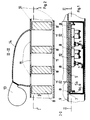
- a box-shaped longitudinal spar of an electric industrial truck is shown, in the interior of which a pulse control for the traction motors or hydraulic and steering auxiliary motors is arranged.
- the pulse control has heat-emitting components 1, 2, which are attached to heat sinks 3, 4 and installed in a metal trough 5.
- the metal trough 5 is sealed with a cover 6 via a lip seal 6a and forms an encapsulated housing.
- the heat loss of the pulse control is via the heat sink 3, 4, the metal pan 5 and a heat sink 7, which is attached to the outside 5a of the metal pan 5 and is used to distribute the heat over the largest possible area, as well as e.g. transfer four contact plates 8 to a frame side wall 9 of a vehicle frame 10 of the electric industrial truck.
- the cooling bodies 3, 4, the cooling plate 7 and the contact plates 8 are preferably made of a good heat-conducting material, e.g. Copper or aluminum. Even in the basic equipment, the vehicle frame 10 is provided with frame slots 11 above and below the pulse control, which form air ducts 12 in connection with the area between the contact plates 8 and make it possible to ventilate the pulse control if necessary.
- a good heat-conducting material e.g. Copper or aluminum.
- a blower 13 preferably a radial blower, is attached above the pulse control, which drives an air flow via an air guiding part 14 through the frame slots 11 and the air guiding channels 12 remaining between the contact plates 8.
- a blower 13 preferably a radial blower
Landscapes
- Engineering & Computer Science (AREA)
- Physics & Mathematics (AREA)
- Thermal Sciences (AREA)
- Microelectronics & Electronic Packaging (AREA)
- Mechanical Engineering (AREA)
- Cooling Or The Like Of Electrical Apparatus (AREA)
- Electric Propulsion And Braking For Vehicles (AREA)
- Devices That Are Associated With Refrigeration Equipment (AREA)
Applications Claiming Priority (2)
| Application Number | Priority Date | Filing Date | Title |
|---|---|---|---|
| DE4023146A DE4023146A1 (de) | 1990-07-20 | 1990-07-20 | Kraftfahrzeug mit einer elektrischen steuerung mit waermeabgebenden bauelementen |
| DE4023146 | 1990-07-20 |
Publications (2)
| Publication Number | Publication Date |
|---|---|
| EP0467151A1 true EP0467151A1 (fr) | 1992-01-22 |
| EP0467151B1 EP0467151B1 (fr) | 1994-03-30 |
Family
ID=6410713
Family Applications (1)
| Application Number | Title | Priority Date | Filing Date |
|---|---|---|---|
| EP91111035A Expired - Lifetime EP0467151B1 (fr) | 1990-07-20 | 1991-07-03 | Véhicule pourvu d'une commande électrique dont les composants dégagent de la chaleur |
Country Status (3)
| Country | Link |
|---|---|
| EP (1) | EP0467151B1 (fr) |
| DE (2) | DE4023146A1 (fr) |
| ES (1) | ES2054401T3 (fr) |
Cited By (5)
| Publication number | Priority date | Publication date | Assignee | Title |
|---|---|---|---|---|
| EP0659599A1 (fr) * | 1993-12-23 | 1995-06-28 | PREH-WERKE GmbH & Co. KG | Régulateur de conditionnement d'air pour véhicule |
| EP0649208A3 (fr) * | 1993-10-19 | 1995-12-13 | Honda Motor Co Ltd | Système de refroidissement pour un chargeur de batterie d'un véhicule électrique. |
| WO1997042060A1 (fr) * | 1996-05-03 | 1997-11-13 | Ford Motor Company Limited | Substrat de recouvrement servant a fixer des dispositifs electroniques dans un vehicule |
| EP1190878A3 (fr) * | 2000-09-22 | 2003-06-18 | Delphi Technologies, Inc. | Commande pour la vitesse d'un ventilateur fixée sur un évaporateur |
| FR2942442A1 (fr) * | 2009-02-26 | 2010-08-27 | Alstom Transp | Ensemble d'une paroi et d'un equipement electrique et vehicule ferroviaire correspondant |
Families Citing this family (2)
| Publication number | Priority date | Publication date | Assignee | Title |
|---|---|---|---|---|
| DE10321549A1 (de) * | 2003-05-14 | 2004-12-02 | Adam Opel Ag | Anordnung zum Kühlen eines Thyristors |
| JP2005117887A (ja) | 2003-09-19 | 2005-04-28 | Auto Network Gijutsu Kenkyusho:Kk | 車載用回路ユニットの取付構造及び車載用回路ユニット |
Citations (3)
| Publication number | Priority date | Publication date | Assignee | Title |
|---|---|---|---|---|
| DE3331890A1 (de) * | 1983-09-03 | 1985-03-28 | Süddeutsche Kühlerfabrik Julius Fr. Behr GmbH & Co KG, 7000 Stuttgart | Kraftfahrzeug-heizungs- und/oder klimaanlage |
| DE3443311A1 (de) * | 1984-11-28 | 1986-06-05 | Daimler-Benz Ag, 7000 Stuttgart | Elektromotorisch antreibbares geblaese fuer eine fahrgastraum-belueftung |
| GB2199203A (en) * | 1986-12-13 | 1988-06-29 | Grundfos Int | A static frequency converter |
-
1990
- 1990-07-20 DE DE4023146A patent/DE4023146A1/de not_active Withdrawn
-
1991
- 1991-07-03 ES ES91111035T patent/ES2054401T3/es not_active Expired - Lifetime
- 1991-07-03 EP EP91111035A patent/EP0467151B1/fr not_active Expired - Lifetime
- 1991-07-03 DE DE91111035T patent/DE59101264D1/de not_active Expired - Fee Related
Patent Citations (3)
| Publication number | Priority date | Publication date | Assignee | Title |
|---|---|---|---|---|
| DE3331890A1 (de) * | 1983-09-03 | 1985-03-28 | Süddeutsche Kühlerfabrik Julius Fr. Behr GmbH & Co KG, 7000 Stuttgart | Kraftfahrzeug-heizungs- und/oder klimaanlage |
| DE3443311A1 (de) * | 1984-11-28 | 1986-06-05 | Daimler-Benz Ag, 7000 Stuttgart | Elektromotorisch antreibbares geblaese fuer eine fahrgastraum-belueftung |
| GB2199203A (en) * | 1986-12-13 | 1988-06-29 | Grundfos Int | A static frequency converter |
Cited By (10)
| Publication number | Priority date | Publication date | Assignee | Title |
|---|---|---|---|---|
| EP0649208A3 (fr) * | 1993-10-19 | 1995-12-13 | Honda Motor Co Ltd | Système de refroidissement pour un chargeur de batterie d'un véhicule électrique. |
| US5647450A (en) * | 1993-10-19 | 1997-07-15 | Honda Giken Kogyo Kabushiki Kaisha | Cooling system included in a battery charger for an electric vehicle |
| CN1043564C (zh) * | 1993-10-19 | 1999-06-09 | 本田技研工业株式会社 | 电动车辆电池充电器中的冷却系统 |
| EP0659599A1 (fr) * | 1993-12-23 | 1995-06-28 | PREH-WERKE GmbH & Co. KG | Régulateur de conditionnement d'air pour véhicule |
| WO1997042060A1 (fr) * | 1996-05-03 | 1997-11-13 | Ford Motor Company Limited | Substrat de recouvrement servant a fixer des dispositifs electroniques dans un vehicule |
| EP1190878A3 (fr) * | 2000-09-22 | 2003-06-18 | Delphi Technologies, Inc. | Commande pour la vitesse d'un ventilateur fixée sur un évaporateur |
| FR2942442A1 (fr) * | 2009-02-26 | 2010-08-27 | Alstom Transp | Ensemble d'une paroi et d'un equipement electrique et vehicule ferroviaire correspondant |
| WO2010097317A1 (fr) * | 2009-02-26 | 2010-09-02 | Alstom Transport Sa | Ensemble d'une paroi et d'un équipement électrique et véhicule ferroviaire correspondant |
| CN102369129A (zh) * | 2009-02-26 | 2012-03-07 | 阿尔斯通运输股份有限公司 | 壁与电气设备的组件以及相应的铁路车辆 |
| CN102369129B (zh) * | 2009-02-26 | 2014-12-17 | 阿尔斯通运输股份有限公司 | 壁与电气设备的组件以及相应的铁路车辆 |
Also Published As
| Publication number | Publication date |
|---|---|
| EP0467151B1 (fr) | 1994-03-30 |
| DE4023146A1 (de) | 1992-01-23 |
| ES2054401T3 (es) | 1994-08-01 |
| DE59101264D1 (de) | 1994-05-05 |
Similar Documents
| Publication | Publication Date | Title |
|---|---|---|
| EP2291064B1 (fr) | Unité électronique dotée de nervures de refroidissement | |
| EP3467854A1 (fr) | Module électrique dans le boîtier de différents matériaux | |
| EP1972483A1 (fr) | Véhicule doté d'un visionneur tête haute | |
| DE6604796U (de) | Abnehmbare waermeaustauschvorrichtung. | |
| DE2532772A1 (de) | Plattenspeicher-laufwerkeinheit | |
| DE102014226849B3 (de) | Schaltschrank mit einer an einem Luftkanal angeordneten zu kühlenden Komponente | |
| DE102014013958A1 (de) | Flüssigkeitsgekühltes Kraftfahrzeugsteuergerät, Kraftfahrzeug mit diesem, sowie Verfahren zur Kühlung eines elektronischen Bauelements eines Kraftfahrzeugsteuergeräts | |
| EP0467151A1 (fr) | Véhicule pourvu d'une commande électrique dont les composants dégagent de la chaleur | |
| DE102010047762A1 (de) | Umrichtermotor, Umrichter und Kühlkörper | |
| EP3567618B1 (fr) | Dispositif d'induction pour charger des véhicules automobiles | |
| EP3468320B1 (fr) | Module électrique dans le boîtier de différents matériaux | |
| EP3467855B1 (fr) | Module électrique | |
| EP1464612B1 (fr) | Chariot élévateur à mât déplaçable | |
| EP3705631A1 (fr) | Machine de travail pourvu d'entraînement électrique et dispositif de refroidissement | |
| EP1095836B2 (fr) | Boîtier sous plancher pour véhicules ferroviaires | |
| EP3716742B1 (fr) | Convertisseur de fréquence et module de convertisseur de fréquence | |
| DE102018111242A1 (de) | Induktionsvorrichtung zum Laden von Kraftfahrzeugen | |
| DE102018111243A1 (de) | Induktionsvorrichtung zum Laden von Kraftfahrzeugen | |
| DE102020215530A1 (de) | E-Achsen-Modul mit einer elektrischen Maschine | |
| EP0582216B1 (fr) | Module redresseur refroidi par liquide avec un cadre de module redresseur | |
| EP0872853A1 (fr) | Dispositif de refroidissement pour des résistances de freinage des véhicules, en particulier des véhicules ferroviaires | |
| DE19629630A1 (de) | Steuergeräteanordnung mit einem elektrischen Anbaugerät | |
| DE1939803A1 (de) | Elektronisches Geraet,insbesondere zum Einbau in Kraftfahrzeuge | |
| DE102019111594A1 (de) | Antriebsanordnung für ein Fahrzeug mit einer elektrischen Maschine und einer Wechselrichtervorrichtung sowie Herstellungsverfahren | |
| DE102018215876A1 (de) | Steuereinrichtung für ein Kraftfahrzeug und Kraftfahrzeug mit einer solchen Steuereinrichtung |
Legal Events
| Date | Code | Title | Description |
|---|---|---|---|
| PUAI | Public reference made under article 153(3) epc to a published international application that has entered the european phase |
Free format text: ORIGINAL CODE: 0009012 |
|
| AK | Designated contracting states |
Kind code of ref document: A1 Designated state(s): DE ES FR GB IT SE |
|
| 17P | Request for examination filed |
Effective date: 19911210 |
|
| 17Q | First examination report despatched |
Effective date: 19930217 |
|
| ITF | It: translation for a ep patent filed | ||
| GRAA | (expected) grant |
Free format text: ORIGINAL CODE: 0009210 |
|
| AK | Designated contracting states |
Kind code of ref document: B1 Designated state(s): DE ES FR GB IT SE |
|
| REF | Corresponds to: |
Ref document number: 59101264 Country of ref document: DE Date of ref document: 19940505 |
|
| GBT | Gb: translation of ep patent filed (gb section 77(6)(a)/1977) |
Effective date: 19940415 |
|
| ET | Fr: translation filed | ||
| REG | Reference to a national code |
Ref country code: ES Ref legal event code: FG2A Ref document number: 2054401 Country of ref document: ES Kind code of ref document: T3 |
|
| EAL | Se: european patent in force in sweden |
Ref document number: 91111035.1 |
|
| PLBE | No opposition filed within time limit |
Free format text: ORIGINAL CODE: 0009261 |
|
| STAA | Information on the status of an ep patent application or granted ep patent |
Free format text: STATUS: NO OPPOSITION FILED WITHIN TIME LIMIT |
|
| 26N | No opposition filed | ||
| PGFP | Annual fee paid to national office [announced via postgrant information from national office to epo] |
Ref country code: GB Payment date: 19950622 Year of fee payment: 5 |
|
| PGFP | Annual fee paid to national office [announced via postgrant information from national office to epo] |
Ref country code: FR Payment date: 19950711 Year of fee payment: 5 |
|
| PGFP | Annual fee paid to national office [announced via postgrant information from national office to epo] |
Ref country code: SE Payment date: 19950717 Year of fee payment: 5 |
|
| PGFP | Annual fee paid to national office [announced via postgrant information from national office to epo] |
Ref country code: ES Payment date: 19950727 Year of fee payment: 5 |
|
| PGFP | Annual fee paid to national office [announced via postgrant information from national office to epo] |
Ref country code: DE Payment date: 19950823 Year of fee payment: 5 |
|
| PG25 | Lapsed in a contracting state [announced via postgrant information from national office to epo] |
Ref country code: GB Effective date: 19960703 |
|
| PG25 | Lapsed in a contracting state [announced via postgrant information from national office to epo] |
Ref country code: SE Effective date: 19960704 Ref country code: ES Free format text: LAPSE BECAUSE OF NON-PAYMENT OF DUE FEES Effective date: 19960704 |
|
| GBPC | Gb: european patent ceased through non-payment of renewal fee |
Effective date: 19960703 |
|
| PG25 | Lapsed in a contracting state [announced via postgrant information from national office to epo] |
Ref country code: FR Effective date: 19970328 |
|
| PG25 | Lapsed in a contracting state [announced via postgrant information from national office to epo] |
Ref country code: DE Effective date: 19970402 |
|
| EUG | Se: european patent has lapsed |
Ref document number: 91111035.1 |
|
| REG | Reference to a national code |
Ref country code: FR Ref legal event code: ST |
|
| REG | Reference to a national code |
Ref country code: ES Ref legal event code: FD2A Effective date: 19970811 |
|
| PG25 | Lapsed in a contracting state [announced via postgrant information from national office to epo] |
Ref country code: IT Free format text: LAPSE BECAUSE OF NON-PAYMENT OF DUE FEES;WARNING: LAPSES OF ITALIAN PATENTS WITH EFFECTIVE DATE BEFORE 2007 MAY HAVE OCCURRED AT ANY TIME BEFORE 2007. THE CORRECT EFFECTIVE DATE MAY BE DIFFERENT FROM THE ONE RECORDED. Effective date: 20050703 |