EP0467189A2 - Kaltwassersatz mit Leistungsanpassung - Google Patents
Kaltwassersatz mit Leistungsanpassung Download PDFInfo
- Publication number
- EP0467189A2 EP0467189A2 EP91111349A EP91111349A EP0467189A2 EP 0467189 A2 EP0467189 A2 EP 0467189A2 EP 91111349 A EP91111349 A EP 91111349A EP 91111349 A EP91111349 A EP 91111349A EP 0467189 A2 EP0467189 A2 EP 0467189A2
- Authority
- EP
- European Patent Office
- Prior art keywords
- cold water
- cooling
- heat exchanger
- condenser
- circuit
- Prior art date
- Legal status (The legal status is an assumption and is not a legal conclusion. Google has not performed a legal analysis and makes no representation as to the accuracy of the status listed.)
- Granted
Links
Images

Classifications
-
- H—ELECTRICITY
- H05—ELECTRIC TECHNIQUES NOT OTHERWISE PROVIDED FOR
- H05K—PRINTED CIRCUITS; CASINGS OR CONSTRUCTIONAL DETAILS OF ELECTRIC APPARATUS; MANUFACTURE OF ASSEMBLAGES OF ELECTRICAL COMPONENTS
- H05K7/00—Constructional details common to different types of electric apparatus
- H05K7/20—Modifications to facilitate cooling, ventilating, or heating
- H05K7/2029—Modifications to facilitate cooling, ventilating, or heating using a liquid coolant with phase change in electronic enclosures
- H05K7/20354—Refrigerating circuit comprising a compressor
-
- F—MECHANICAL ENGINEERING; LIGHTING; HEATING; WEAPONS; BLASTING
- F25—REFRIGERATION OR COOLING; COMBINED HEATING AND REFRIGERATION SYSTEMS; HEAT PUMP SYSTEMS; MANUFACTURE OR STORAGE OF ICE; LIQUEFACTION SOLIDIFICATION OF GASES
- F25B—REFRIGERATION MACHINES, PLANTS OR SYSTEMS; COMBINED HEATING AND REFRIGERATION SYSTEMS; HEAT PUMP SYSTEMS
- F25B49/00—Arrangement or mounting of control or safety devices
- F25B49/02—Arrangement or mounting of control or safety devices for compression type machines, plants or systems
- F25B49/027—Condenser control arrangements
-
- F—MECHANICAL ENGINEERING; LIGHTING; HEATING; WEAPONS; BLASTING
- F25—REFRIGERATION OR COOLING; COMBINED HEATING AND REFRIGERATION SYSTEMS; HEAT PUMP SYSTEMS; MANUFACTURE OR STORAGE OF ICE; LIQUEFACTION SOLIDIFICATION OF GASES
- F25D—REFRIGERATORS; COLD ROOMS; ICE-BOXES; COOLING OR FREEZING APPARATUS NOT OTHERWISE PROVIDED FOR
- F25D17/00—Arrangements for circulating cooling fluids; Arrangements for circulating gas, e.g. air, within refrigerated spaces
- F25D17/02—Arrangements for circulating cooling fluids; Arrangements for circulating gas, e.g. air, within refrigerated spaces for circulating liquids, e.g. brine
Definitions
- the invention relates to a chiller with performance adjustment to the heat generation of cooling objects, in particular data processing systems at constant cold water inlet temperature, consisting of a refrigeration unit with a vaporizer, a compressor, a condenser and a refrigerant circuit containing an expansion valve, and a cold water circuit in the heat exchange with the evaporator
- the refrigeration unit stands and at least one consumer, as well as a heat exchanger through which the refrigerant flows in the cold water supply circuit, which compensates for the difference between the cooling capacity and the heat output to be dissipated by a control element that creates a shunt in the cold water circuit to the heat exchanger and that depends on a control device that regulates the constant cold water flow temperature.
- the hot refrigerant vapor flows through this heat exchanger as a heat carrier and thereby heats the cooling water flowing around it in the cooling water circuit.
- the control of the cooling water temperature is achieved in that a mixing valve is inserted between the consumer, the heat exchanger and the evaporator, whereby the cooling water can be led past this heat valve either via the heat exchanger or via a shunt to the heat exchanger, with a constant reduction in the cooling water led through the heat exchanger through the mixing valve is possible.
- the mixing valve is controlled by a control device.
- the disturbance variable for the control of the mixing valve is taken from the cold water flow.
- the cooling water is circulated by a pump. Basically, this arrangement can also be carried out with a water-cooled condenser. In both cases, however, the condenser and the heat exchanger are independent, structurally separate devices.
- the object of the present invention is therefore to create a chiller, in particular for cooling data technology equipment, which has a simplified structure with the same optimum performance.
- the chiller according to the invention is designed such that the condenser is also the part of the heat exchanger through which the coolant flows.
- the control element can either be a continuously variable mixing valve or consist of two solenoid valves clocked in opposite directions.
- a fan is assigned to the condenser for cooling.
- This control concept allows emergency operation even if the refrigerant circuit is damaged if the heat exchanger is converted into a water cooler. For this it is necessary that the entire cooling water is passed through the heat exchanger and the fan may be switched to a higher speed in order to keep the water heating within limits.
- the water chiller can also be designed such that the elements (fins, tubes) of the cooling circuit are mixed with the elements of the cooling circuit in an alternating manner. This arrangement enables an intimate constructive mixing of elements (e.g. fins or pipes) of the cooling circuit with the cooling circuit to intensify the heat coupling.
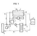
- the water is recooled via the refrigerant circuit 11.
- This consists of the evaporator 4, the compressor 1, the condenser 2K and the expansion valve 3.
- the function of such a cooling circuit is that the amount of heat is reduced at low temperature and released again at higher temperature becomes. To go through this cycle, work must be done on this cycle from an external source. The amount of heat dissipated at the higher temperature is greater than the heat equivalent of the work put into the cycle.
- the evaporator 4 be stands in the simplest case from cooling coils, which are attached, for example, as pipe registers in a cold room.
- the steam is drawn off from the compressor 1, which increases the pressure of the gaseous refrigerant to such an extent that the condensation temperature of the refrigerant is now high enough to condense in the air-cooled condenser 2K.
- the heat energy contained in the evaporated refrigerant is released into the air and the now liquid refrigerant is fed via the expansion valve 3 to the evaporator 4, in which the pressure is low.
- the control of the cooling water temperature is achieved in that the cooling water circuit contains a secondary circuit, which is more or less switched on via the valve 8 depending on the desired temperature and in which the heat exchanger 2W is located, which is structurally combined with the condenser, the condenser 2K at the same time is the part of the heat exchanger 2W through which the cooling water flows. Condenser 2K and heat exchanger 2W are thermally closely coupled to the air flow of the fan 5 by this structural union 2.
- the disturbance variable for the control of the three-way valve 8 is taken from the cold water return.
- the cooling water is circulated via the pump 6 and an overflow vessel 7 is also provided in the control circuit 12, the condenser 2K is cooled by the fan 5.
- FIG. 2a shows schematically the front view of the condenser heat exchanger combination 2.
- FIG. 2b shows the associated front view.
- the heat exchanger 2W with the coolant lines K lies above the condenser part 2K with the coolant lines KM.
- the heat is coupled via fins L running perpendicular to it.
- FIG. 3 shows an embodiment in which there is an even closer coupling of the heat exchanger and the condenser part.
- a heat exchanger part 2W alternates with a condenser part 2K. This subdivision can be repeated any number of times.
- the fins are the common coupling elements for the heat exchanger and the condenser part.
- the cooling air KL is blown from below through the fins L through the fan, not shown.
Landscapes
- Engineering & Computer Science (AREA)
- Physics & Mathematics (AREA)
- Thermal Sciences (AREA)
- General Engineering & Computer Science (AREA)
- Mechanical Engineering (AREA)
- Microelectronics & Electronic Packaging (AREA)
- Combustion & Propulsion (AREA)
- Chemical & Material Sciences (AREA)
- Devices That Are Associated With Refrigeration Equipment (AREA)
- Thermotherapy And Cooling Therapy Devices (AREA)
- General Induction Heating (AREA)
- Oscillators With Electromechanical Resonators (AREA)
- Soil Working Implements (AREA)
- Sorption Type Refrigeration Machines (AREA)
Abstract
Description
- Die Erfindung betrifft einen Kaltwassersatz mit Leistungsanpassung an die Wärmeerzeugung von Kühlobjekten, insbesondere Datenverarbeitungsanlagen bei konstanter Kaltwasservorlauftemperatur, bestehend aus einem Kälteaggregat mit wengistens einem Verdampfer, einem Kompressor, einem Kondensator und einem ein Expansionsventil enthaltenden Kältemittelkreis, sowie einen Kaltwasserkreis der im Wärmetausch mit dem Verdampfer des Kälteaggregats steht und wenigstens einem Verbraucher, sowie einen im Kaltwasservorlaufkreis vom Kältemittel durchflossenen Wärmetauscher, der die Differenz zwischen Kühlleistung und abzuführender Wärmeleistung durch ein Steuerelement ausgleicht, das einen Nebenschluß im Kaltwasserkreis zum Wärmetauscher herstellt und das abhängig von einer auf konstante Kaltwasservorlauftemperatur regelnden Regeleinrichtung ist.
- Aus der deutschen Patentschrift 31 30 390 ist bereits ein Kaltwassersatz mit Leistunganpassung an die Wärmeerzeugung von Kühlobjekten bei konstanter Kaltwasservorlauftemperatur bekannt. Bei diesem Kaltwassersatz übersteigt die Kühlleistung des Kaltwasserkreises unter allen Betriebsbedingungen die vom Verbraucher abzuführende Wärmeleistung und er enthält im Kaltwasservorlaufkreis einen vom Kühlmittel durchflossenen Wärmetauscher der die Differenz zwischen Kühlleistung und abzuführender Wärmeleistung ausgleicht. Der Wärmetauscher liegt dabei entweder parallel oder in Reihe zum Kondensator und ist als eigenständiges Bauteil ausgeführt bei dem sowohl ein Kühlmittelkreis und ein Kaltwasserkreis vorhanden ist.
- Dieser Wärmetauscher wird vom heißen Kältemitteldampf als Wärmeträger durchströmt und erwärmt dadurch das ihn umströmende Kühlwasser des Kühlwasserkreislaufes. Die Regelung der Kühlwassertemperatur wird dadurch erreicht, daß zwischen dem Verbraucher, dem Wärmetauscher und dem Verdampfer ein Mischventil eingefügt ist, wobei durch dieses Mischventil das Kühlwasser entweder über den Wärmetauscher oder über einen Nebenschluß an den Wärmetauscher vorbeigeführt werden kann, wobei auch eine stetige Verminderung des durch den Wärmetauscher geführten Kühlwassers durch das Mischventil möglich ist. Gesteuert wird das Mischventil über eine Regeleinrichtung. Die Störgröße für die Steuerung des Mischventils wird dabei dem Kaltwasservorlauf entnommen. Die Umwälzung des Kühlwassers erfolgt über eine Pumpe. Grundsätzlich läßt sich diese Anordnung auch mit einem wassergekühlten Kondensator ausführen. In beiden Fällen sind jedoch Kondensator und Wärmetauscher selbständige baulich voneinander getrennte Einrichtungen.
- Obwohl die Regelung dieses Kaltwassersatzes alle an sie gestellten Anforderungen erfüllt ist jedoch der Aufwand durch den zusätzlichen Wärmetauscher sowohl von der Platzfrage als auch von der Kostenfrage her nicht unerheblich.
- Aufgabe der vorliegenden Erfindung ist es daher, einen Kaltwassersatz, insbesondere zur Kühlung von Einrichtungen der Datentechnik zu schaffen, der bei gleicher optimaler Leistung einen vereinfachten Aufbau aufweist.
- Zur Lösung dieser Aufgabe wird der Kaltwassersatz gemäß der Erfindung derart ausgebildet, daß der Kondensator zugleich der kühlmitteldurchflossene Teil des Wärmetauschers ist.
- Durch diese Maßnahmen erhält man den Vorteil, daß der Kältekreis vereinfacht und nur der Verdichter ein Teil mit aufwendiger Wartung ist.
- Das Steuerelement kann entweder ein stetig veränderbares Mischventil sein oder aus zwei gegensinnig getakteten Magnetventilen bestehen.
- Zur Kühlung wird dem Kondensator ein Ventilator zugeordnet.
- Dieses Regelkonzept erlaubt auch im Falle eines Kältemittelkreisschadens einen Notbetrieb wenn der Wärmetauscher als Wasserkühler umfunktioniert wird. Dazu ist notwendig, daß das gesamte Kühlwasser über den Wärmetauscher geleitet und eventuell der Ventilator auf höhere Drehzahl geschaltet wird um die Wassererwärmung in Grenzen zu halten.
- In weiterer Ausgestaltung läßt sich der Kaltwassersatz auch so ausbilden, daß die Elemente (Lamellen, Rohre) des Kühlkreises mit den Elementen des Kältekreises untereinander abwechselnd vermengt sind. Diese Anordnung ermöglicht eine innige konstruktive Vermengung von Elementen (z.B. Lamellen oder Rohre) des Kühlkreises mit dem Kältekreis zur Intensivierung der Wärmekopplung.
- Anhand der Ausführungsbeispiele nach den FIG 1 bis 3 wird die Erfindung näher erläutert: Es zeigen
- FIG 1 ein Prinzipschaltbild,
- FIG 2 ein spezielle Ausgestaltung und
- FIG 3 eine weitere spezielle Ausgestaltung.
- Wie in FIG 1 gezeigt, wird die im Verbraucher 9, der z.B. die Zentraleinheit eines Rechners sein kann, entstehende Wärme über dem Kühlwasserkreis 10 abgeführt. Die Rückkühlung des Wassers erfolgt dabei über den Kältemittelkreis 11. Dieser besteht aus dem Verdampfer 4, dem Kompressor 1, dem Kondensator 2K und dem Expansionsventil 3. Die Funktion eines solches Kühlkreislaufes ist die, daß Wärmemenge bei tiefer Temperatur abgenommen und bei höherer Temperatur wieder abgegeben wird. Zum Durchlaufen dieses Kreisprozesses muß von einer äußeren Quelle an diesen Kreislauf Arbeit geleistet werden. Die Wärmemenge, die bei der höheren Temperatur abgeführt wird, ist größer als das Wärmeäquivalent der in den Kreisprozeß gesteckten Arbeit. Der Verdampfer 4 besteht im einfachsten Fall aus Kühlschlangen, die beispielsweise als Rohrregister in einem Kühlraum angebracht sind. In diesen Rohren strömt eine Flüssigkeit, das sogenannte Kältemittel, deren Siedetemperatur tiefer liegt als die Temperatur des Kühlraumes, im speziellen Falle tiefer als die Tempeperatur des vom Verbraucher 9 abgeführten Wassers. Dadurch wird dem Wasser des Kühlwasserkreislaufes Wärmeenergie entzogen, durch die Rohre an das Kältemittel übertragen, das dadurch verdampft wird. Der Dampf wird vom Kompressor 1 abgezogen, der den Druck des gasförmigen Kältemittels soweit erhöht, daß nun die Kondensationstemperatur des Kältemittels hoch genug ist um im luftgekühlten Kondensator 2K zu kondensieren. Dabei wird die im verdampften Kältemittel enthaltene Wärmeenergie an die Luft abgegeben und das nun wieder flüssige Kältemittel über das Expansionsventil 3 dem Verdampfer 4 zugeführt in dem ein niedriger Druck herrscht. Die Regelung der Kühlwassertemperatur wird dadurch erreicht, daß der Kühlwasserkreis einen Nebenkreis enthält, der über das Ventil 8 je nach gewünschter Temperatur mehr oder weniger zugeschaltet wird und in dem der Wärmetauscher 2W liegt, der baulich mit dem Kondensator vereinigt ist, wobei der Kondensator 2K zugleich das kältemitteldurchflossene Teil des Wärmetauschers 2W ist, der vom Kühlwasser durchflossen wird. Kondensator 2K und Wärmetauscher 2W sind durch diese bauliche Vereinigung 2 unmittelbar mit dem Luftstrom des Ventilators 5 thermisch eng gekoppelt. Die Störgröße für die Steuerung des Dreiwegeventils 8 wird dabei dem Kaltwasserrücklauf entnommen. Die Umwälzung des Kühlwassers erfolgt über die Pumpe 6 zugleich ist im Regelkreis 12 ein Überlaufgefäß 7 vorgesehen, der Kondensator 2K wird durch den Ventilator 5 gekühlt.
- FIG 2a zeigt schematisch die Vorderansicht der Kondensatorwärmetauscherkombination 2. FIG 2b die dazugehörige Vorderansicht.
- Der Wärmetauscher 2W mit den Kühlmittelleitungen K liegt oberhalb des Kondensatorteils 2K mit den Kältemittelleitungen KM. Die Wärmekopplung erfolgt über senkrecht dazu verlaufende Lamellen L.
- Eine Ausführungsform, bei der noch eine innigere Verkopplung von Wärmetauscher und Kondensatorteil gegeben ist, zeigt FIG 3. Dort wechselt jeweils ein Wärmetauscherteil 2W mit einem Kondensatorteil 2K ab. Diese Unterteilung läßt sich beliebig oft wiederholen. Auch hier sind die Lamellen wieder die gemeinsamen Kopplungsglieder für Wärmetauscher und Kondensatorteil. Die Kühlluft KL wird über dem nicht dargestellten Ventilator von unten durch die Lamellen L geblasen.
Claims (6)
Applications Claiming Priority (2)
| Application Number | Priority Date | Filing Date | Title |
|---|---|---|---|
| DE4023140 | 1990-07-20 | ||
| DE4023140 | 1990-07-20 |
Publications (3)
| Publication Number | Publication Date |
|---|---|
| EP0467189A2 true EP0467189A2 (de) | 1992-01-22 |
| EP0467189A3 EP0467189A3 (en) | 1992-03-25 |
| EP0467189B1 EP0467189B1 (de) | 1995-02-08 |
Family
ID=6410709
Family Applications (1)
| Application Number | Title | Priority Date | Filing Date |
|---|---|---|---|
| EP91111349A Expired - Lifetime EP0467189B1 (de) | 1990-07-20 | 1991-07-08 | Kaltwassersatz mit Leistungsanpassung |
Country Status (3)
| Country | Link |
|---|---|
| EP (1) | EP0467189B1 (de) |
| AT (1) | ATE118270T1 (de) |
| DE (1) | DE59104534D1 (de) |
Cited By (7)
| Publication number | Priority date | Publication date | Assignee | Title |
|---|---|---|---|---|
| DE4312134A1 (de) * | 1993-03-05 | 1994-09-08 | Escher Wyss Gmbh | Kühleinrichtung |
| EP0766308A3 (de) * | 1995-09-29 | 1998-06-10 | General Electric Company | Reduzierte Temperaturzyklen von wassergekühlten elektronischen Leistungsbauelementen |
| EP1731858A1 (de) * | 2005-06-10 | 2006-12-13 | Nova Frigo S.p.A. | Ausgleichungserzeuger für eine Kühlanlage |
| CN104713204A (zh) * | 2013-12-11 | 2015-06-17 | 珠海格力电器股份有限公司 | 空调机组及控制方法 |
| EP2903076A1 (de) * | 2014-01-27 | 2015-08-05 | Liebherr-Transportation Systems GmbH & Co. KG | Fahrzeugkühlkreislauf |
| CN112050536A (zh) * | 2020-09-15 | 2020-12-08 | 安徽江淮汽车集团股份有限公司 | 一种恒温冷却水循环供给系统及循环供给方法 |
| US11852388B2 (en) | 2017-07-14 | 2023-12-26 | Efficient Energy Gmbh | Heat pump arrangement having a controllable heat exchanger and method for producing a heat pump arrangement |
Families Citing this family (1)
| Publication number | Priority date | Publication date | Assignee | Title |
|---|---|---|---|---|
| DE102008057110B4 (de) | 2008-11-13 | 2011-07-14 | Wolf GmbH, 84048 | Kühlvorrichtung |
Family Cites Families (10)
| Publication number | Priority date | Publication date | Assignee | Title |
|---|---|---|---|---|
| US1937984A (en) * | 1930-06-24 | 1933-12-05 | Southern Oregon Sales Inc | Refrigerating control system and method |
| FR811014A (fr) * | 1935-12-23 | 1937-04-05 | Dispositif pour le conditionnement de l'air | |
| DE1014134B (de) * | 1955-08-09 | 1957-08-22 | Wilhelm Bock | Kombinierter luft- und wassergekuehlter Lamellen- oder Rippen-Kondensator fuer Kaeltemaschinen |
| US3859812A (en) * | 1974-03-08 | 1975-01-14 | Richard B Pavlak | Methods and apparatus for treating machine tool coolants |
| EP0075570A1 (de) * | 1981-04-01 | 1983-04-06 | DE DIETRICH & Cie, Société dite | Heizvorrichtung mit drei strömenden medien, die mit einem rekuperator und einer wärmeübertragungseinheit für eine heizung verbunden sind |
| DE3130390C2 (de) * | 1981-07-31 | 1987-02-05 | Siemens AG, 1000 Berlin und 8000 München | Kaltwassersatz |
| US4495777A (en) * | 1983-01-10 | 1985-01-29 | Babington Thomas G | Load shaving system |
| US4653287A (en) * | 1985-01-28 | 1987-03-31 | Martin Jr James B | System for heating and cooling liquids |
| US4769998A (en) * | 1986-04-25 | 1988-09-13 | Advantage Electronics, Incorporated | Precision-controlled water chiller |
| DE3700708A1 (de) * | 1987-01-13 | 1988-07-21 | Wilhelm Bader | Vorrichtung zur waermeabfuhr aus elektrische einrichtungen aufweisenden gehaeusen oder schaltschraenken |
-
1991
- 1991-07-08 EP EP91111349A patent/EP0467189B1/de not_active Expired - Lifetime
- 1991-07-08 DE DE59104534T patent/DE59104534D1/de not_active Expired - Fee Related
- 1991-07-08 AT AT91111349T patent/ATE118270T1/de not_active IP Right Cessation
Cited By (8)
| Publication number | Priority date | Publication date | Assignee | Title |
|---|---|---|---|---|
| DE4312134A1 (de) * | 1993-03-05 | 1994-09-08 | Escher Wyss Gmbh | Kühleinrichtung |
| EP0766308A3 (de) * | 1995-09-29 | 1998-06-10 | General Electric Company | Reduzierte Temperaturzyklen von wassergekühlten elektronischen Leistungsbauelementen |
| EP1731858A1 (de) * | 2005-06-10 | 2006-12-13 | Nova Frigo S.p.A. | Ausgleichungserzeuger für eine Kühlanlage |
| CN104713204A (zh) * | 2013-12-11 | 2015-06-17 | 珠海格力电器股份有限公司 | 空调机组及控制方法 |
| EP2903076A1 (de) * | 2014-01-27 | 2015-08-05 | Liebherr-Transportation Systems GmbH & Co. KG | Fahrzeugkühlkreislauf |
| US11852388B2 (en) | 2017-07-14 | 2023-12-26 | Efficient Energy Gmbh | Heat pump arrangement having a controllable heat exchanger and method for producing a heat pump arrangement |
| CN112050536A (zh) * | 2020-09-15 | 2020-12-08 | 安徽江淮汽车集团股份有限公司 | 一种恒温冷却水循环供给系统及循环供给方法 |
| CN112050536B (zh) * | 2020-09-15 | 2021-09-21 | 安徽江淮汽车集团股份有限公司 | 一种恒温冷却水循环供给系统及循环供给方法 |
Also Published As
| Publication number | Publication date |
|---|---|
| DE59104534D1 (de) | 1995-03-23 |
| ATE118270T1 (de) | 1995-02-15 |
| EP0467189A3 (en) | 1992-03-25 |
| EP0467189B1 (de) | 1995-02-08 |
Similar Documents
| Publication | Publication Date | Title |
|---|---|---|
| DE69519179T2 (de) | Apparat und verfahren zum kühlen eines produktes | |
| EP1533116B1 (de) | Temperiervorrichtung für Druckmaschinen | |
| DE10359204B4 (de) | Luftgekühlte Wärmetauschvorrichtung | |
| EP0411172A1 (de) | Kühleinrichtung für mehrere Kühlmittelkreisläufe | |
| DE3027447A1 (de) | Vorrichtung zur be- und entlueftung | |
| DE20105487U1 (de) | Kühlgerät mit mehreren Arbeitsmodi zur Optimierung der Effektivität. | |
| DE3028304A1 (de) | Waermeaustauscher | |
| DE2606072A1 (de) | Verfahren und anlage zur steuerung der temperatur in mehreren raeumen, die wechselseitig unterschiedlichen und sich veraendernden waermebedarf haben, wobei einige der raeume normalerweise einen kuehlbedarf haben | |
| EP2514290A1 (de) | System und verfahren zur kühlung einer rechenanlage | |
| EP0467189B1 (de) | Kaltwassersatz mit Leistungsanpassung | |
| EP0007396B1 (de) | Kühleinrichtung für in geschlossenen Gehäusen angeordnete elektrische Baueinheiten | |
| DE19524115C2 (de) | Stromrichtergerät mit unterteilten Funktionsräumen | |
| DE19813157A1 (de) | Raumlufttechnische Anlage zur bivalenten Klimatisierung eines Raumes | |
| DE3341853C2 (de) | Einrichtung zum Kühlen von Innenräumen | |
| DE112017007720T5 (de) | Kühlkörper | |
| DE3130390C2 (de) | Kaltwassersatz | |
| EP3791123B1 (de) | Kühlsystem sowie verfahren zum temperieren eines rechenzentrums unter nutzung eines kühlsystems | |
| DE2219208C3 (de) | Anlage zum Temperieren von Räumen mit einer umschaltbaren Wärmepumpe | |
| DE102023106917A1 (de) | Wärmerückgewinnungsmodul für ein Präzisionsklimatisierungssystem, Präzisionsklimatisierungssystem sowie Verfahren zu dessen Betrieb | |
| EP2397805B1 (de) | Vorrichtung zur Rückkühlung von Wärmeträgern und Arbeitsstoffen aus der Kältetechnik und Flüssigkeitskühlern sowie Kälterückgewinnung in der Lüftungstechnik | |
| EP1259769B1 (de) | Vorrichtung zum erzeugen von kaltwasser für raumkühlung | |
| DE2839638A1 (de) | Trockenkuehlsystem fuer kraftwerkanlagen | |
| DE102022004555A1 (de) | Vorrichtung zum Temperieren zweier Medien | |
| DE20008740U1 (de) | Heißluft-Trockeneinrichtung | |
| DE19509716A1 (de) | Kühlanlage mit freier Kühlung |
Legal Events
| Date | Code | Title | Description |
|---|---|---|---|
| PUAI | Public reference made under article 153(3) epc to a published international application that has entered the european phase |
Free format text: ORIGINAL CODE: 0009012 |
|
| AK | Designated contracting states |
Kind code of ref document: A2 Designated state(s): AT BE CH DE FR GB IT LI NL |
|
| PUAL | Search report despatched |
Free format text: ORIGINAL CODE: 0009013 |
|
| AK | Designated contracting states |
Kind code of ref document: A3 Designated state(s): AT BE CH DE FR GB IT LI NL |
|
| 17P | Request for examination filed |
Effective date: 19920423 |
|
| 17Q | First examination report despatched |
Effective date: 19930423 |
|
| GRAA | (expected) grant |
Free format text: ORIGINAL CODE: 0009210 |
|
| AK | Designated contracting states |
Kind code of ref document: B1 Designated state(s): AT BE CH DE FR GB IT LI NL |
|
| REF | Corresponds to: |
Ref document number: 118270 Country of ref document: AT Date of ref document: 19950215 Kind code of ref document: T |
|
| REF | Corresponds to: |
Ref document number: 59104534 Country of ref document: DE Date of ref document: 19950323 |
|
| ITF | It: translation for a ep patent filed | ||
| ET | Fr: translation filed | ||
| GBT | Gb: translation of ep patent filed (gb section 77(6)(a)/1977) |
Effective date: 19950421 |
|
| PGFP | Annual fee paid to national office [announced via postgrant information from national office to epo] |
Ref country code: AT Payment date: 19950628 Year of fee payment: 5 |
|
| PG25 | Lapsed in a contracting state [announced via postgrant information from national office to epo] |
Ref country code: LI Effective date: 19950731 Ref country code: CH Effective date: 19950731 Ref country code: BE Effective date: 19950731 |
|
| PLBE | No opposition filed within time limit |
Free format text: ORIGINAL CODE: 0009261 |
|
| STAA | Information on the status of an ep patent application or granted ep patent |
Free format text: STATUS: NO OPPOSITION FILED WITHIN TIME LIMIT |
|
| 26N | No opposition filed | ||
| BERE | Be: lapsed |
Owner name: SIEMENS NIXDORF INFORMATIONSSYSTEME A.G. Effective date: 19950731 |
|
| PG25 | Lapsed in a contracting state [announced via postgrant information from national office to epo] |
Ref country code: NL Effective date: 19960201 |
|
| REG | Reference to a national code |
Ref country code: CH Ref legal event code: PL |
|
| NLV4 | Nl: lapsed or anulled due to non-payment of the annual fee |
Effective date: 19960201 |
|
| PG25 | Lapsed in a contracting state [announced via postgrant information from national office to epo] |
Ref country code: AT Effective date: 19960708 |
|
| PGFP | Annual fee paid to national office [announced via postgrant information from national office to epo] |
Ref country code: GB Payment date: 19980623 Year of fee payment: 8 |
|
| PGFP | Annual fee paid to national office [announced via postgrant information from national office to epo] |
Ref country code: FR Payment date: 19980729 Year of fee payment: 8 |
|
| PGFP | Annual fee paid to national office [announced via postgrant information from national office to epo] |
Ref country code: DE Payment date: 19980917 Year of fee payment: 8 |
|
| PG25 | Lapsed in a contracting state [announced via postgrant information from national office to epo] |
Ref country code: GB Free format text: LAPSE BECAUSE OF NON-PAYMENT OF DUE FEES Effective date: 19990708 |
|
| PG25 | Lapsed in a contracting state [announced via postgrant information from national office to epo] |
Ref country code: FR Free format text: THE PATENT HAS BEEN ANNULLED BY A DECISION OF A NATIONAL AUTHORITY Effective date: 19990731 |
|
| GBPC | Gb: european patent ceased through non-payment of renewal fee |
Effective date: 19990708 |
|
| PG25 | Lapsed in a contracting state [announced via postgrant information from national office to epo] |
Ref country code: DE Free format text: LAPSE BECAUSE OF NON-PAYMENT OF DUE FEES Effective date: 20000503 |
|
| REG | Reference to a national code |
Ref country code: FR Ref legal event code: ST |
|
| PG25 | Lapsed in a contracting state [announced via postgrant information from national office to epo] |
Ref country code: IT Free format text: LAPSE BECAUSE OF NON-PAYMENT OF DUE FEES;WARNING: LAPSES OF ITALIAN PATENTS WITH EFFECTIVE DATE BEFORE 2007 MAY HAVE OCCURRED AT ANY TIME BEFORE 2007. THE CORRECT EFFECTIVE DATE MAY BE DIFFERENT FROM THE ONE RECORDED. Effective date: 20050708 |