EP0467247B1 - Montagesystem für Dieselpartikelfilter - Google Patents
Montagesystem für Dieselpartikelfilter Download PDFInfo
- Publication number
- EP0467247B1 EP0467247B1 EP91111709A EP91111709A EP0467247B1 EP 0467247 B1 EP0467247 B1 EP 0467247B1 EP 91111709 A EP91111709 A EP 91111709A EP 91111709 A EP91111709 A EP 91111709A EP 0467247 B1 EP0467247 B1 EP 0467247B1
- Authority
- EP
- European Patent Office
- Prior art keywords
- particulate
- tourniquet
- trap
- particulate trapping
- shell
- Prior art date
- Legal status (The legal status is an assumption and is not a legal conclusion. Google has not performed a legal analysis and makes no representation as to the accuracy of the status listed.)
- Expired - Lifetime
Links
Images


Classifications
-
- F—MECHANICAL ENGINEERING; LIGHTING; HEATING; WEAPONS; BLASTING
- F01—MACHINES OR ENGINES IN GENERAL; ENGINE PLANTS IN GENERAL; STEAM ENGINES
- F01N—GAS-FLOW SILENCERS OR EXHAUST APPARATUS FOR MACHINES OR ENGINES IN GENERAL; GAS-FLOW SILENCERS OR EXHAUST APPARATUS FOR INTERNAL-COMBUSTION ENGINES
- F01N3/00—Exhaust or silencing apparatus having means for purifying, rendering innocuous, or otherwise treating exhaust
- F01N3/08—Exhaust or silencing apparatus having means for purifying, rendering innocuous, or otherwise treating exhaust for rendering innocuous
- F01N3/10—Exhaust or silencing apparatus having means for purifying, rendering innocuous, or otherwise treating exhaust for rendering innocuous by thermal or catalytic conversion of noxious components of exhaust
- F01N3/24—Exhaust or silencing apparatus having means for purifying, rendering innocuous, or otherwise treating exhaust for rendering innocuous by thermal or catalytic conversion of noxious components of exhaust characterised by constructional aspects of converting apparatus
- F01N3/28—Construction of catalytic reactors
- F01N3/2839—Arrangements for mounting catalyst support in housing, e.g. with means for compensating thermal expansion or vibration
- F01N3/2853—Arrangements for mounting catalyst support in housing, e.g. with means for compensating thermal expansion or vibration using mats or gaskets between catalyst body and housing
- F01N3/2864—Arrangements for mounting catalyst support in housing, e.g. with means for compensating thermal expansion or vibration using mats or gaskets between catalyst body and housing the mats or gaskets comprising two or more insulation layers
-
- F—MECHANICAL ENGINEERING; LIGHTING; HEATING; WEAPONS; BLASTING
- F01—MACHINES OR ENGINES IN GENERAL; ENGINE PLANTS IN GENERAL; STEAM ENGINES
- F01N—GAS-FLOW SILENCERS OR EXHAUST APPARATUS FOR MACHINES OR ENGINES IN GENERAL; GAS-FLOW SILENCERS OR EXHAUST APPARATUS FOR INTERNAL-COMBUSTION ENGINES
- F01N3/00—Exhaust or silencing apparatus having means for purifying, rendering innocuous, or otherwise treating exhaust
- F01N3/02—Exhaust or silencing apparatus having means for purifying, rendering innocuous, or otherwise treating exhaust for cooling, or for removing solid constituents of, exhaust
- F01N3/021—Exhaust or silencing apparatus having means for purifying, rendering innocuous, or otherwise treating exhaust for cooling, or for removing solid constituents of, exhaust by means of filters
- F01N3/0211—Arrangements for mounting filtering elements in housing, e.g. with means for compensating thermal expansion or vibration
-
- F—MECHANICAL ENGINEERING; LIGHTING; HEATING; WEAPONS; BLASTING
- F01—MACHINES OR ENGINES IN GENERAL; ENGINE PLANTS IN GENERAL; STEAM ENGINES
- F01N—GAS-FLOW SILENCERS OR EXHAUST APPARATUS FOR MACHINES OR ENGINES IN GENERAL; GAS-FLOW SILENCERS OR EXHAUST APPARATUS FOR INTERNAL-COMBUSTION ENGINES
- F01N3/00—Exhaust or silencing apparatus having means for purifying, rendering innocuous, or otherwise treating exhaust
- F01N3/02—Exhaust or silencing apparatus having means for purifying, rendering innocuous, or otherwise treating exhaust for cooling, or for removing solid constituents of, exhaust
- F01N3/021—Exhaust or silencing apparatus having means for purifying, rendering innocuous, or otherwise treating exhaust for cooling, or for removing solid constituents of, exhaust by means of filters
- F01N3/022—Exhaust or silencing apparatus having means for purifying, rendering innocuous, or otherwise treating exhaust for cooling, or for removing solid constituents of, exhaust by means of filters characterised by specially adapted filtering structure, e.g. honeycomb, mesh or fibrous
- F01N3/0222—Exhaust or silencing apparatus having means for purifying, rendering innocuous, or otherwise treating exhaust for cooling, or for removing solid constituents of, exhaust by means of filters characterised by specially adapted filtering structure, e.g. honeycomb, mesh or fibrous the structure being monolithic, e.g. honeycombs
-
- F—MECHANICAL ENGINEERING; LIGHTING; HEATING; WEAPONS; BLASTING
- F01—MACHINES OR ENGINES IN GENERAL; ENGINE PLANTS IN GENERAL; STEAM ENGINES
- F01N—GAS-FLOW SILENCERS OR EXHAUST APPARATUS FOR MACHINES OR ENGINES IN GENERAL; GAS-FLOW SILENCERS OR EXHAUST APPARATUS FOR INTERNAL-COMBUSTION ENGINES
- F01N3/00—Exhaust or silencing apparatus having means for purifying, rendering innocuous, or otherwise treating exhaust
- F01N3/02—Exhaust or silencing apparatus having means for purifying, rendering innocuous, or otherwise treating exhaust for cooling, or for removing solid constituents of, exhaust
- F01N3/021—Exhaust or silencing apparatus having means for purifying, rendering innocuous, or otherwise treating exhaust for cooling, or for removing solid constituents of, exhaust by means of filters
- F01N3/031—Exhaust or silencing apparatus having means for purifying, rendering innocuous, or otherwise treating exhaust for cooling, or for removing solid constituents of, exhaust by means of filters having means for by-passing filters, e.g. when clogged or during cold engine start
-
- F—MECHANICAL ENGINEERING; LIGHTING; HEATING; WEAPONS; BLASTING
- F01—MACHINES OR ENGINES IN GENERAL; ENGINE PLANTS IN GENERAL; STEAM ENGINES
- F01N—GAS-FLOW SILENCERS OR EXHAUST APPARATUS FOR MACHINES OR ENGINES IN GENERAL; GAS-FLOW SILENCERS OR EXHAUST APPARATUS FOR INTERNAL-COMBUSTION ENGINES
- F01N3/00—Exhaust or silencing apparatus having means for purifying, rendering innocuous, or otherwise treating exhaust
- F01N3/08—Exhaust or silencing apparatus having means for purifying, rendering innocuous, or otherwise treating exhaust for rendering innocuous
- F01N3/10—Exhaust or silencing apparatus having means for purifying, rendering innocuous, or otherwise treating exhaust for rendering innocuous by thermal or catalytic conversion of noxious components of exhaust
- F01N3/24—Exhaust or silencing apparatus having means for purifying, rendering innocuous, or otherwise treating exhaust for rendering innocuous by thermal or catalytic conversion of noxious components of exhaust characterised by constructional aspects of converting apparatus
- F01N3/28—Construction of catalytic reactors
- F01N3/2839—Arrangements for mounting catalyst support in housing, e.g. with means for compensating thermal expansion or vibration
- F01N3/2853—Arrangements for mounting catalyst support in housing, e.g. with means for compensating thermal expansion or vibration using mats or gaskets between catalyst body and housing
- F01N3/2857—Arrangements for mounting catalyst support in housing, e.g. with means for compensating thermal expansion or vibration using mats or gaskets between catalyst body and housing the mats or gaskets being at least partially made of intumescent material, e.g. unexpanded vermiculite
-
- F—MECHANICAL ENGINEERING; LIGHTING; HEATING; WEAPONS; BLASTING
- F01—MACHINES OR ENGINES IN GENERAL; ENGINE PLANTS IN GENERAL; STEAM ENGINES
- F01N—GAS-FLOW SILENCERS OR EXHAUST APPARATUS FOR MACHINES OR ENGINES IN GENERAL; GAS-FLOW SILENCERS OR EXHAUST APPARATUS FOR INTERNAL-COMBUSTION ENGINES
- F01N3/00—Exhaust or silencing apparatus having means for purifying, rendering innocuous, or otherwise treating exhaust
- F01N3/08—Exhaust or silencing apparatus having means for purifying, rendering innocuous, or otherwise treating exhaust for rendering innocuous
- F01N3/10—Exhaust or silencing apparatus having means for purifying, rendering innocuous, or otherwise treating exhaust for rendering innocuous by thermal or catalytic conversion of noxious components of exhaust
- F01N3/24—Exhaust or silencing apparatus having means for purifying, rendering innocuous, or otherwise treating exhaust for rendering innocuous by thermal or catalytic conversion of noxious components of exhaust characterised by constructional aspects of converting apparatus
- F01N3/28—Construction of catalytic reactors
- F01N3/2839—Arrangements for mounting catalyst support in housing, e.g. with means for compensating thermal expansion or vibration
- F01N3/2853—Arrangements for mounting catalyst support in housing, e.g. with means for compensating thermal expansion or vibration using mats or gaskets between catalyst body and housing
- F01N3/2867—Arrangements for mounting catalyst support in housing, e.g. with means for compensating thermal expansion or vibration using mats or gaskets between catalyst body and housing the mats or gaskets being placed at the front or end face of catalyst body
-
- F—MECHANICAL ENGINEERING; LIGHTING; HEATING; WEAPONS; BLASTING
- F01—MACHINES OR ENGINES IN GENERAL; ENGINE PLANTS IN GENERAL; STEAM ENGINES
- F01N—GAS-FLOW SILENCERS OR EXHAUST APPARATUS FOR MACHINES OR ENGINES IN GENERAL; GAS-FLOW SILENCERS OR EXHAUST APPARATUS FOR INTERNAL-COMBUSTION ENGINES
- F01N2330/00—Structure of catalyst support or particle filter
- F01N2330/06—Ceramic, e.g. monoliths
-
- F—MECHANICAL ENGINEERING; LIGHTING; HEATING; WEAPONS; BLASTING
- F01—MACHINES OR ENGINES IN GENERAL; ENGINE PLANTS IN GENERAL; STEAM ENGINES
- F01N—GAS-FLOW SILENCERS OR EXHAUST APPARATUS FOR MACHINES OR ENGINES IN GENERAL; GAS-FLOW SILENCERS OR EXHAUST APPARATUS FOR INTERNAL-COMBUSTION ENGINES
- F01N2350/00—Arrangements for fitting catalyst support or particle filter element in the housing
- F01N2350/02—Fitting ceramic monoliths in a metallic housing
- F01N2350/04—Fitting ceramic monoliths in a metallic housing with means compensating thermal expansion
-
- F—MECHANICAL ENGINEERING; LIGHTING; HEATING; WEAPONS; BLASTING
- F01—MACHINES OR ENGINES IN GENERAL; ENGINE PLANTS IN GENERAL; STEAM ENGINES
- F01N—GAS-FLOW SILENCERS OR EXHAUST APPARATUS FOR MACHINES OR ENGINES IN GENERAL; GAS-FLOW SILENCERS OR EXHAUST APPARATUS FOR INTERNAL-COMBUSTION ENGINES
- F01N2410/00—By-passing, at least partially, exhaust from inlet to outlet of apparatus, to atmosphere or to other device
- F01N2410/04—By-passing, at least partially, exhaust from inlet to outlet of apparatus, to atmosphere or to other device during regeneration period, e.g. of particle filter
-
- F—MECHANICAL ENGINEERING; LIGHTING; HEATING; WEAPONS; BLASTING
- F01—MACHINES OR ENGINES IN GENERAL; ENGINE PLANTS IN GENERAL; STEAM ENGINES
- F01N—GAS-FLOW SILENCERS OR EXHAUST APPARATUS FOR MACHINES OR ENGINES IN GENERAL; GAS-FLOW SILENCERS OR EXHAUST APPARATUS FOR INTERNAL-COMBUSTION ENGINES
- F01N2450/00—Methods or apparatus for fitting, inserting or repairing different elements
- F01N2450/02—Fitting monolithic blocks into the housing
-
- F—MECHANICAL ENGINEERING; LIGHTING; HEATING; WEAPONS; BLASTING
- F02—COMBUSTION ENGINES; HOT-GAS OR COMBUSTION-PRODUCT ENGINE PLANTS
- F02B—INTERNAL-COMBUSTION PISTON ENGINES; COMBUSTION ENGINES IN GENERAL
- F02B3/00—Engines characterised by air compression and subsequent fuel addition
- F02B3/06—Engines characterised by air compression and subsequent fuel addition with compression ignition
-
- Y—GENERAL TAGGING OF NEW TECHNOLOGICAL DEVELOPMENTS; GENERAL TAGGING OF CROSS-SECTIONAL TECHNOLOGIES SPANNING OVER SEVERAL SECTIONS OF THE IPC; TECHNICAL SUBJECTS COVERED BY FORMER USPC CROSS-REFERENCE ART COLLECTIONS [XRACs] AND DIGESTS
- Y02—TECHNOLOGIES OR APPLICATIONS FOR MITIGATION OR ADAPTATION AGAINST CLIMATE CHANGE
- Y02T—CLIMATE CHANGE MITIGATION TECHNOLOGIES RELATED TO TRANSPORTATION
- Y02T10/00—Road transport of goods or passengers
- Y02T10/10—Internal combustion engine [ICE] based vehicles
- Y02T10/12—Improving ICE efficiencies
-
- Y—GENERAL TAGGING OF NEW TECHNOLOGICAL DEVELOPMENTS; GENERAL TAGGING OF CROSS-SECTIONAL TECHNOLOGIES SPANNING OVER SEVERAL SECTIONS OF THE IPC; TECHNICAL SUBJECTS COVERED BY FORMER USPC CROSS-REFERENCE ART COLLECTIONS [XRACs] AND DIGESTS
- Y10—TECHNICAL SUBJECTS COVERED BY FORMER USPC
- Y10S—TECHNICAL SUBJECTS COVERED BY FORMER USPC CROSS-REFERENCE ART COLLECTIONS [XRACs] AND DIGESTS
- Y10S55/00—Gas separation
- Y10S55/30—Exhaust treatment
Definitions
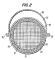
- the prior art uses clamp shell 52 to radially compress trap element 50. Since the radial pressure applied by clamp shell 52 on trap element 50 cannot be controlled effectively, many traps are manufactured with loose trap elements. Moreover, heat developed in the trap during normal operation or regeneration causes thermal expansion differentials which may result in loose trap elements. Therefore, it has been necessary in the prior art to include retaining ring 54 mounted on both the upstream and downstream side of trap element 50 to provide axial retention of trap element 50. However, in performing this necessary function, retaining ring 54 covers a portion of the outer periphery 58 of element 50.
Landscapes
- Engineering & Computer Science (AREA)
- Chemical & Material Sciences (AREA)
- Chemical Kinetics & Catalysis (AREA)
- Combustion & Propulsion (AREA)
- Mechanical Engineering (AREA)
- General Engineering & Computer Science (AREA)
- Health & Medical Sciences (AREA)
- Toxicology (AREA)
- Processes For Solid Components From Exhaust (AREA)
- Filtering Of Dispersed Particles In Gases (AREA)
Claims (11)
- Partikelfiltervorrichtung (10) mit einem äußeren Gehäuse (11), das einen Gaseinlaß (14), einen Gasauslaß (15) und einen den Gaseinlaß (14) und den Gasauslaß (15) verbindenden Durchgang (17) aufweist, mit einem im Durchgang (17) des Gehäuses (11) angeordneten Partikelfilterelement (13), das zur Filterung der in dem durch den Durchgang (17) strömenden Gas enthaltenen Partikel dient, und mit Montagevorrichtungen (21, 25, 26; 28, 29; 22) für die Befestigung des Partikelfilterelementes (13) in radialer und axialer Richtung innerhalb des Durchganges (17),
dadurch gekennzeichnet,
daß eine das Partikelfilterelement (13) umgebende Ummantelung (19) vorgesehen ist, um einen vorgegebenen radialen Druck auf das Partikelfilterelement (13) auszuüben, der im wesentlichen unabhängig von den Umfangsabmessungen des Durchganges (17) und der Partiklelfiltervorrichtung (13) ist,
daß die Ummantelung (19) eine einstellbare äußere Umfangsabmessung aufweist, um eine Anpassung der Umfangsabmessung der Ummantelung (19) an die Umfangsabmessung des Partikelfilterelements (13) zu ermöglichen, wobei die Ummantelung (19) entgegengesetzte Enden aufweist, die relativ zueinander umfangseitig einstellbar sind, um die einstellbare Umfangsabmessung für die Erzielung des vorbestimmten radialen Druckes einzustellen,
daß die Ummantelung (19) Befestigungsvorrichtungen für ein Halten der Enden in einer vorgegebenen relativen Position zueinander entprechend der Anwendung des vorbestimmten radialen Druckes auf das Partikelfilterelement (13) aufweist,
daß die Montagevorrichtungen (21, 25, 26; 28, 29; 22) das Partikelfilterelement (13) radial und axial innerhalb des Durchganges (17) in einer Weise halten, daß keine weitere wesentliche radiale zusammendrückende Kraft auf das Partikelfilterelement (13) ausgeübt wird, und nur an einem Ende das Partikelfilterelement (13) axial einklemmen, während das andere Ende axial beweglich ist, so daß ein temperaturbedingtes Ausdehnen und Zusammenziehen des Partikelfilterelements (13) auftreten kann, ohne daß zerstörerische Kräfte innerhalb des Partikelfilterelements (13) auftreten. - Vorrichtung nach Anspruch 1, wobei eine elastische Vorrichtung (20) zwischen der Ummantelung (19) und der äußeren Oberfläche des Partikelfilterelements (13) für ein Tragen des Partikelfilterelements (13) vorgesehen ist, und wobei vorzugsweise die elastische Vorrichtung (20) eine oder mehrere Schichten aus hitzebeständigem Material aufweist.
- Vorrichtung nach Anspruch 1, wobei das Partikelfilterelement (13) aus einem porösem keramischen Material gebildet ist.
- Vorrichtung nach Anspruch 2, wobei weiterhin eine Erosionsschutzvorrichtung (32, 34) vorgesehen ist, um die elastische Vorrichtung vor dem Gas zu schützen.
- Vorrichtung nach einem der Ansprüche 1 bis 4, wobei die Montagevorrichtung mindestens ein mit der Ummantelung (19) verbundenes Verlängerungselement (21, 22, 29, 40, 41) aufweist, das über die radiale Abmessung des Partikelfilterelements (13) hinausragt.
- Vorrichtung nach Anspruch 5, wobei die Montagevorrichtung eine Haltevorrichtung für einen Eingriff mit den Verlängerungselementen (21, 29, 40) aufweist, um das Partikelfilterelement (13) in radialer und axialer Richtung zu halten,
und/oder wobei die Montagevorrichtung ein Paar von Verlängerungselementen aufweist, die integral mit der Ummantelung (19) ausgebildet sind, wobei das Verlängerungselement jeweils einen der ringförmigen Montageringe (40, 41) aufweist, die axial entlang des Partikelfilterelements (13) beabstandet angeordnet sind,
und vorzugsweise wobei die Haltevorrichtung ein Paar von ringförmigen Rippen (25, 25') aufweist, die an der inneren Wand des Gehäuses (11) an den de Verlängerungselementen gegenüberliegenden Seiten ausgebildet sind,
und/oder wobei eine ringförmige Vertiefung (28) in dem Gehäuse ausgebildet ist, die so ausgestaltet und angeordnet ist, daß sie das Verlängerungselement fest in axialer Beziehung innerhalb des Gehäuses (11) hält. - Vorrichtung nach einem der Ansprüche 1 bis 6, wobei die Montagevorrichtung lösbar das Partikelfilterelement (13) innerhalb des Gehäuses (11) hält,
und/oder wobei das Partikelfilterelement (13) einen vorbestimmten Flußweg mit einer radialen, sich über die gesamte radiale Abmessung des Partikelfilterelements (13) erstreckende Querschnittsabmessung aufweist, wobei die Montagevorrichtung das Partikelfilterelement innerhalb des Durchganges (17) des Gehäuses (11) in einer Weise hält, daß im wesentlichen keine Blockierung der vollen radialen Abmessung des Flußweges durch das Partikelfilterelement (13) auftritt. - Vorrichtung nach einem der Ansprüche 1 bis 7, wobei das äußere Gehäuse (11) mindestens ein Paar von Schalen (27, 36) aufweist, die entlang einem Paar von axialen Nähten miteinander verbunden sind.
- Vorrichtung nach Anspruch 8, wobei das äußere Gehäuse (11) eine innere Schale (18) und ein Paar von äußeren Schalen (27, 36) aufweist, wobei die innere Schale (18) mit einer der äußeren Schalen (27) verbunden ist, um den Teil des Durchganges (17) zu bilden, in dem das Partikelfilterelement (13) befestigt ist,
und vorzugsweise wobei die verbleibende äußere Schale (36) mit der inneren Schale (18) und der äußeren Schale (27) verbunden ist, um einen Bypass (37) für einen Gasfluß vom Einlaß (14) zum Auslaß (15) um das Partikelfilterelement herum zu bilden,
und vorzugsweise wobei jede der Schalen (18, 27, 36) mit einem Paar von sich radial erstreckenden Flanschen versehen ist, die eine relativ feste Umfangsabmessung definieren,
und vorzugsweise wobei die Flansche so ausgebildet und angeordnet sind, daß sie entlang des Paares von axialen Nähten (35) miteinander verbunden sind, um den Durchgang (17) und den Bypass (37) zu bilden, die Umfangsabmessungen aufweisen, die durch die Umfangsabmessungen der Schalen (18, 27, 36) vorgegeben sind. - Verfahren zur Herstellung einer Partikelfiltervorrichtung (10), die ein Partikelfilterelement (13) mit einer Umfangsabmessung aufweist, die wesentlichen Herstellungstoleranzen ausgesetzt ist,
dadurch gekennzeichnet,
daß weiterhin eine Ummantelung (19) vorgesehen ist, die um das Partikelfilterelement (13) herum angeordnet ist und eine einstellbare Umfangsabmessung für die Anwendung einer kontrollierbaren radialen Kraft auf das Filterelement (13) aufweist und
daß weiterhin die Verfahrensschritte vorgesehen sind:
Anordnen der Ummantelung (19) um das Partikelfilterelement (13) herum,
Einstellen der Ummantelung (19), um eine vorbestimmte radiale Kraft auf das Partikelfilterelement (13) auszuüben,
Befestigen der Ummantelung (19), um die eingestellte Umfangsabmessung in einer entsprechenden Position entsprechend der vorbestimmten radialen Kraft zu halten, und
Montieren des Partikelfilterelementes (13) in einem Gehäuse (11), um einen Durchgang (17) für das durch das Partikelfilterelement (13) strömende Gas zu bilden, während keine weitere wesentliche radiale zusammendrückende Kraft auf das Partikelfilterelement (13) ausgeübt wird. - Verfahren nach Anspruch 10, wobei die folgenden Schritte vorgesehen sind:
Abdecken des Partikelfilterelementes (13) mit einer elastischen Schicht (20), bevor die Ummantelung (19) um das Partikelfilterelement (13) herum angeordnet wird, und
Befestigen mindestens eines Montageringes (21, 22, 29) an der Ummantelung (19),
und wobei vorzugsweise die weiteren Schritte vorgesehen sind:
Anwendung eines Hitzebehandlungsverfahrens auf das Partikelfilterelement (13) und
Versehen der elastischen Schicht (20) mit Randerosionsschutzvorrichtungen (32, 34), und wobei vorzugsweise der weitere Schritt vorgesehen ist:
Rollen der Enden der Ummantelung (19), um die Randerosionsschutzvorrichtungen (32,34) zu befestigen.
Applications Claiming Priority (2)
| Application Number | Priority Date | Filing Date | Title |
|---|---|---|---|
| US552460 | 1990-07-16 | ||
| US07/552,460 US5082479A (en) | 1990-07-16 | 1990-07-16 | Diesel particulate trap mounting system |
Publications (2)
| Publication Number | Publication Date |
|---|---|
| EP0467247A1 EP0467247A1 (de) | 1992-01-22 |
| EP0467247B1 true EP0467247B1 (de) | 1995-12-27 |
Family
ID=24205433
Family Applications (1)
| Application Number | Title | Priority Date | Filing Date |
|---|---|---|---|
| EP91111709A Expired - Lifetime EP0467247B1 (de) | 1990-07-16 | 1991-07-13 | Montagesystem für Dieselpartikelfilter |
Country Status (4)
| Country | Link |
|---|---|
| US (1) | US5082479A (de) |
| EP (1) | EP0467247B1 (de) |
| JP (1) | JPH0729013B2 (de) |
| DE (1) | DE69115777T2 (de) |
Families Citing this family (41)
| Publication number | Priority date | Publication date | Assignee | Title |
|---|---|---|---|---|
| JP3131540B2 (ja) * | 1994-08-04 | 2001-02-05 | 日本碍子株式会社 | 集塵装置におけるフィルタエレメントの支持構造 |
| EP0837229B1 (de) | 1996-10-15 | 2002-04-24 | Corning Incorporated | Verfahren zur Herstellung eines Katalysators einer Brennkraftmaschine |
| EP0856646A1 (de) | 1997-02-03 | 1998-08-05 | Corning Incorporated | Verfahren zur Herstellung eines Katalysators einer Brennkraftmaschine |
| US6101714A (en) * | 1997-09-08 | 2000-08-15 | Corning Incorporated | Method of making a catalytic converter for use in an internal combustion engine |
| AU2034800A (en) | 1998-12-18 | 2000-07-12 | Corning Incorporated | A catalytic converter for use in an internal combustion engine and a method of making |
| US6317976B1 (en) | 1998-12-28 | 2001-11-20 | Corning Incorporated | Method of making a catalytic converter for use in an internal combustion engine |
| US7211226B2 (en) * | 2000-03-09 | 2007-05-01 | Fleetgaurd, Inc. | Catalyst and filter combination |
| US6776814B2 (en) | 2000-03-09 | 2004-08-17 | Fleetguard, Inc. | Dual section exhaust aftertreatment filter and method |
| US7052532B1 (en) | 2000-03-09 | 2006-05-30 | 3M Innovative Properties Company | High temperature nanofilter, system and method |
| US6484397B1 (en) | 2000-07-11 | 2002-11-26 | Corning Incorporated | Method of assembling a catalytic converter for use in an internal combustion engine |
| US6544310B2 (en) | 2001-05-24 | 2003-04-08 | Fleetguard, Inc. | Exhaust aftertreatment filter with particulate distribution pattern |
| US20040116276A1 (en) * | 2002-02-12 | 2004-06-17 | Aleksey Yezerets | Exhaust aftertreatment emission control regeneration |
| DE10300780A1 (de) * | 2003-01-11 | 2004-07-22 | J. Eberspächer GmbH & Co. KG | Abgasbehandlungseinrichtung |
| FR2869639B1 (fr) | 2004-04-29 | 2009-06-12 | Peugeot Citroen Automobiles Sa | Procede de determination de la charge d'un piege pour substances polluantes |
| US7393386B2 (en) * | 2004-10-06 | 2008-07-01 | Fleetguard, Inc. | Exhaust aftertreatment filter with residual stress control |
| KR20070085768A (ko) * | 2004-12-14 | 2007-08-27 | 가부시키가이샤 데프로 | 디젤 엔진의 배기정화장치 및 제어장치 |
| US7340888B2 (en) * | 2005-04-26 | 2008-03-11 | Donaldson Company, Inc. | Diesel particulate matter reduction system |
| US20060242951A1 (en) * | 2005-04-29 | 2006-11-02 | Caterpillar Inc. | Refractory material retention device |
| DE102005022512A1 (de) * | 2005-05-11 | 2006-11-16 | J. Eberspächer GmbH & Co. KG | Herstellungsverfahren für eine Abgasbehandlungsvorrichtung |
| US7862640B2 (en) | 2006-03-21 | 2011-01-04 | Donaldson Company, Inc. | Low temperature diesel particulate matter reduction system |
| KR100836200B1 (ko) * | 2007-04-26 | 2008-06-09 | 세종공업 주식회사 | 분리형 배기가스 정화장치 |
| DE102008016236A1 (de) * | 2008-03-27 | 2009-10-01 | J. Eberspächer GmbH & Co. KG | Abgasbehandlungseinrichtung |
| US8281581B2 (en) * | 2008-10-20 | 2012-10-09 | Deere & Company | Construction for an exhaust after treatment device |
| DE102010015271A1 (de) | 2010-04-15 | 2011-10-20 | J. Eberspächer GmbH & Co. KG | Abgasbehandlungseinrichtung |
| US20130199371A1 (en) * | 2010-04-22 | 2013-08-08 | International Engine Intellectual Property Company Llc | Reduction of fouling in after treatment components |
| DE102010034743A1 (de) | 2010-08-19 | 2012-02-23 | J. Eberspächer GmbH & Co. KG | Abgasreinigungsvorrichtung, Abgasanlage, Ausbauverfahren |
| DE102011014457A1 (de) | 2011-03-19 | 2011-11-10 | Daimler Ag | Werkzeug zum Montieren und Demontieren eines Partikelfilters |
| US8820691B2 (en) | 2012-06-28 | 2014-09-02 | Electro-Motive Diesel, Inc. | Adjustable support structure for an after-treatment component |
| US8875500B2 (en) | 2012-08-23 | 2014-11-04 | Electro-Motive Diesel, Inc. | Mounting foot for an after-treatment component |
| US9097168B2 (en) | 2012-08-23 | 2015-08-04 | Electro-Motive Diesel, Inc. | Bracket for an after-treatment component |
| US8943816B2 (en) | 2012-08-23 | 2015-02-03 | Electro-Motive Diesel, Inc. | Mounting system for an after-treatment component |
| US9010096B2 (en) | 2012-08-24 | 2015-04-21 | Tenneco Automotive Operating Company Inc. | Exhaust component mounting system |
| US9464550B2 (en) | 2012-12-21 | 2016-10-11 | Caterpillar Inc. | System and method for retaining aftertreatment bricks |
| US9086007B2 (en) | 2012-12-21 | 2015-07-21 | Caterpillar Inc. | System and method for accommodating aftertreatment bricks |
| US9050559B2 (en) | 2013-03-01 | 2015-06-09 | Caterpillar Inc. | System and method for accommodating aftertreatment bricks |
| JP6232257B2 (ja) * | 2013-10-28 | 2017-11-15 | ヤンマー株式会社 | 排気ガス浄化システム及びこれを備えた船舶 |
| US10443469B2 (en) | 2013-10-28 | 2019-10-15 | Yanmar Co., Ltd. | Exhaust gas purification system and ship having the same |
| JP6228427B2 (ja) * | 2013-10-28 | 2017-11-08 | ヤンマー株式会社 | 船舶の排気ガス浄化システム |
| WO2016153955A1 (en) | 2015-03-23 | 2016-09-29 | Corning Incorporated | Exhaust gas treatment article and methods of manufacturing same |
| WO2016182806A1 (en) | 2015-05-08 | 2016-11-17 | Corning Incorporated | Housing, fluid stream treatment article, exhaust system and methods of manufacturing same |
| CN114991909B (zh) * | 2022-06-08 | 2024-06-21 | 南京开特环保科技有限公司 | 一种汽油机尾气颗粒捕集器外壳 |
Family Cites Families (18)
| Publication number | Priority date | Publication date | Assignee | Title |
|---|---|---|---|---|
| US4093423A (en) * | 1972-10-03 | 1978-06-06 | Volkswagenwerk Aktiengesellschaft | Catalytic device for the catalytic purification of exhaust gases |
| GB1455855A (en) * | 1973-04-07 | 1976-11-17 | British Leyland Uk Ltd | Apparatus for fabricating a catalytic device for an exhaust system for an internal combustion engine |
| US4148120A (en) * | 1974-07-16 | 1979-04-10 | Volkswagenwerk Aktiengesellschaft | Method of manufacturing a catalyst for catalytic purification of exhaust gases |
| DE7541252U (de) * | 1975-12-24 | 1976-04-29 | Paul Gillet Gmbh, 6732 Edenkoben | Vorrichtung zum reinigen der abgase von brennkraftmaschinen |
| GB1568303A (en) * | 1977-03-04 | 1980-05-29 | Foseco Int | Duplex copying transfer system |
| US4425304A (en) * | 1981-01-20 | 1984-01-10 | Toyo Kogyo Co., Ltd. | Catalytic converter |
| EP0072059B1 (de) * | 1981-08-11 | 1986-05-07 | BBC Aktiengesellschaft Brown, Boveri & Cie. | Aufgeladene Brennkraftmaschine mit Abgaspartikelfilter |
| JPS59208119A (ja) * | 1983-05-13 | 1984-11-26 | Sankei Giken Kogyo Kk | 触媒コンバ−タ |
| US4504294A (en) * | 1983-07-08 | 1985-03-12 | Arvin Industries, Inc. | Exhaust processor assembly |
| EP0318462B1 (de) * | 1984-08-13 | 1991-10-23 | Arvin Industries, Inc. | Abgasreiniger |
| US4625511A (en) * | 1984-08-13 | 1986-12-02 | Arvin Industries, Inc. | Exhaust processor |
| DE3567696D1 (en) * | 1984-11-30 | 1989-02-23 | Bbc Brown Boveri & Cie | Exhaust particles filter for internal-combustion engines |
| SE456104B (sv) * | 1986-06-16 | 1988-09-05 | Sandvik Ab | Anordning for katalytisk rening av avgaser fran forbrenningsmotor |
| US4851015A (en) * | 1987-08-21 | 1989-07-25 | Donaldson Company, Inc. | Muffler apparatus with filter trap and method of use |
| DE8715289U1 (de) * | 1987-11-18 | 1988-01-14 | Emitec Gesellschaft für Emissionstechnologie mbH, 53797 Lohmar | Trägerkörper für einen katalytischen Reaktor zur Abgasreinigung |
| US4878928A (en) * | 1988-07-28 | 1989-11-07 | Donaldson Company, Inc. | Apparatus for increasing regenerative filter heating element temperature |
| DE3834779A1 (de) * | 1988-10-12 | 1990-04-19 | Roth Technik Gmbh | Bauteilsatz fuer einen katalysator |
| US4923487A (en) * | 1988-10-17 | 1990-05-08 | The Duriron Company, Inc. | Cross flow diesel particulate trap |
-
1990
- 1990-07-16 US US07/552,460 patent/US5082479A/en not_active Expired - Lifetime
-
1991
- 1991-07-13 DE DE69115777T patent/DE69115777T2/de not_active Expired - Fee Related
- 1991-07-13 EP EP91111709A patent/EP0467247B1/de not_active Expired - Lifetime
- 1991-07-16 JP JP3268115A patent/JPH0729013B2/ja not_active Expired - Lifetime
Non-Patent Citations (1)
| Title |
|---|
| WO 89/01566 * |
Also Published As
| Publication number | Publication date |
|---|---|
| JPH0729013B2 (ja) | 1995-04-05 |
| JPH06178906A (ja) | 1994-06-28 |
| US5082479A (en) | 1992-01-21 |
| DE69115777D1 (de) | 1996-02-08 |
| EP0467247A1 (de) | 1992-01-22 |
| DE69115777T2 (de) | 1996-05-15 |
Similar Documents
| Publication | Publication Date | Title |
|---|---|---|
| EP0467247B1 (de) | Montagesystem für Dieselpartikelfilter | |
| EP0837229B1 (de) | Verfahren zur Herstellung eines Katalysators einer Brennkraftmaschine | |
| EP1235976B1 (de) | Vorrichtung zur behandlung von gasstrom | |
| US4163042A (en) | Containers for catalysts for exhaust emission control | |
| US3990859A (en) | Exhaust systems for internal combustion engines | |
| KR100871482B1 (ko) | 엔진 배기가스의 오염 제거용 세척장치 | |
| US20040109795A1 (en) | Cleanable device for depolluting an engine exhaust gases | |
| JPH01270920A (ja) | ガス用フィルタ | |
| US4923487A (en) | Cross flow diesel particulate trap | |
| US4207661A (en) | Method of fabricating a catalyst converter for cleaning exhausts of cars | |
| MX2010010797A (es) | Aparato para tratar una corriente de gas de escape con un modulo removible. | |
| US4148120A (en) | Method of manufacturing a catalyst for catalytic purification of exhaust gases | |
| US3937617A (en) | Catalytic converter for automotive internal combustion engine | |
| WO2010065764A2 (en) | Apparatus, system, and method for insulating an exhaust aftertreatment component | |
| EP0050340B1 (de) | Auspuff-Filtervorrichtung zum Auffangen von festen Abgasbestandteilen eines Motors und Verfahren zu deren Herstellung | |
| US4070158A (en) | Catalyst for catalytic purification of exhaust gases | |
| US4203949A (en) | Catalyst converter for cleaning exhausts of cars | |
| JP3989039B2 (ja) | ばいじん除去装置 | |
| US7503956B2 (en) | Exhaust treatment device with adjustable retention collar | |
| US4224285A (en) | Smoke filter for internal combustion engines | |
| JP2000104530A (ja) | 排気ガス浄化装置 | |
| JPS6140896Y2 (de) | ||
| JP4453151B2 (ja) | 排気ガス浄化用触媒コンバータ | |
| JPS6140895Y2 (de) | ||
| JPH0742534A (ja) | ディーゼル機関の排気微粒子除去装置 |
Legal Events
| Date | Code | Title | Description |
|---|---|---|---|
| PUAI | Public reference made under article 153(3) epc to a published international application that has entered the european phase |
Free format text: ORIGINAL CODE: 0009012 |
|
| AK | Designated contracting states |
Kind code of ref document: A1 Designated state(s): DE GB |
|
| 17P | Request for examination filed |
Effective date: 19920527 |
|
| 17Q | First examination report despatched |
Effective date: 19930830 |
|
| GRAA | (expected) grant |
Free format text: ORIGINAL CODE: 0009210 |
|
| AK | Designated contracting states |
Kind code of ref document: B1 Designated state(s): DE GB |
|
| REF | Corresponds to: |
Ref document number: 69115777 Country of ref document: DE Date of ref document: 19960208 |
|
| PLBE | No opposition filed within time limit |
Free format text: ORIGINAL CODE: 0009261 |
|
| STAA | Information on the status of an ep patent application or granted ep patent |
Free format text: STATUS: NO OPPOSITION FILED WITHIN TIME LIMIT |
|
| 26N | No opposition filed | ||
| PGFP | Annual fee paid to national office [announced via postgrant information from national office to epo] |
Ref country code: GB Payment date: 19980626 Year of fee payment: 8 |
|
| PG25 | Lapsed in a contracting state [announced via postgrant information from national office to epo] |
Ref country code: GB Free format text: LAPSE BECAUSE OF NON-PAYMENT OF DUE FEES Effective date: 19990713 |
|
| GBPC | Gb: european patent ceased through non-payment of renewal fee |
Effective date: 19990713 |
|
| PGFP | Annual fee paid to national office [announced via postgrant information from national office to epo] |
Ref country code: DE Payment date: 20070831 Year of fee payment: 17 |
|
| PG25 | Lapsed in a contracting state [announced via postgrant information from national office to epo] |
Ref country code: DE Free format text: LAPSE BECAUSE OF NON-PAYMENT OF DUE FEES Effective date: 20090203 |