EP0467285A2 - Dispositif pour le déplacement d'un support pour pipettes dans un analyseur - Google Patents
Dispositif pour le déplacement d'un support pour pipettes dans un analyseur Download PDFInfo
- Publication number
- EP0467285A2 EP0467285A2 EP91111834A EP91111834A EP0467285A2 EP 0467285 A2 EP0467285 A2 EP 0467285A2 EP 91111834 A EP91111834 A EP 91111834A EP 91111834 A EP91111834 A EP 91111834A EP 0467285 A2 EP0467285 A2 EP 0467285A2
- Authority
- EP
- European Patent Office
- Prior art keywords
- pipette
- tray
- pipettes
- stop member
- pipette tray
- Prior art date
- Legal status (The legal status is an assumption and is not a legal conclusion. Google has not performed a legal analysis and makes no representation as to the accuracy of the status listed.)
- Granted
Links
Images



Classifications
-
- G—PHYSICS
- G01—MEASURING; TESTING
- G01N—INVESTIGATING OR ANALYSING MATERIALS BY DETERMINING THEIR CHEMICAL OR PHYSICAL PROPERTIES
- G01N35/00—Automatic analysis not limited to methods or materials provided for in any single one of groups G01N1/00 - G01N33/00; Handling materials therefor
- G01N35/10—Devices for transferring samples or any liquids to, in, or from, the analysis apparatus, e.g. suction devices, injection devices
- G01N35/1065—Multiple transfer devices
-
- G—PHYSICS
- G01—MEASURING; TESTING
- G01N—INVESTIGATING OR ANALYSING MATERIALS BY DETERMINING THEIR CHEMICAL OR PHYSICAL PROPERTIES
- G01N1/00—Sampling; Preparing specimens for investigation
- G01N1/28—Preparing specimens for investigation including physical details of (bio-)chemical methods covered elsewhere, e.g. G01N33/50, C12Q
- G01N1/38—Diluting, dispersing or mixing samples
-
- G—PHYSICS
- G01—MEASURING; TESTING
- G01N—INVESTIGATING OR ANALYSING MATERIALS BY DETERMINING THEIR CHEMICAL OR PHYSICAL PROPERTIES
- G01N35/00—Automatic analysis not limited to methods or materials provided for in any single one of groups G01N1/00 - G01N33/00; Handling materials therefor
- G01N35/02—Automatic analysis not limited to methods or materials provided for in any single one of groups G01N1/00 - G01N33/00; Handling materials therefor using a plurality of sample containers moved by a conveyor system past one or more treatment or analysis stations
- G01N35/04—Details of the conveyor system
- G01N2035/0474—Details of actuating means for conveyors or pipettes
- G01N2035/0475—Details of actuating means for conveyors or pipettes electric, e.g. stepper motor, solenoid
-
- G—PHYSICS
- G01—MEASURING; TESTING
- G01N—INVESTIGATING OR ANALYSING MATERIALS BY DETERMINING THEIR CHEMICAL OR PHYSICAL PROPERTIES
- G01N35/00—Automatic analysis not limited to methods or materials provided for in any single one of groups G01N1/00 - G01N33/00; Handling materials therefor
- G01N35/02—Automatic analysis not limited to methods or materials provided for in any single one of groups G01N1/00 - G01N33/00; Handling materials therefor using a plurality of sample containers moved by a conveyor system past one or more treatment or analysis stations
- G01N35/04—Details of the conveyor system
- G01N2035/0474—Details of actuating means for conveyors or pipettes
- G01N2035/0482—Transmission
- G01N2035/0484—Belt or chain
Definitions
- the present invention relates to a device for translatorily moving a plate-shaped pipette tray equipped with pipettes arranged in the direction of tray movement to the processing station of an analyzer for alignment therein.
- An analyzer is known from DE-A-19 21 302 in which trays equipped with cuvettes are moved along a feed path and past a processing station.
- the trays are provided with slots cooperating with a feed mechanism.
- a mechanical latching means engages with said slots in order to fix a cuvette exactly in the processing station. Due to its many mechanical components, this known analyzer is of a complex design and operates awkwardly.
- the object is attained in that
- the invention provides for a pipette tray resting on the continuous movement means driven by the stepping motor first to be moved towards the stop member and after reversal of the stepping motor returned to its processing position by one or more indexing steps in the opposite direction. In this way, each pipette is reliably and exactly aligned in its processing station.
- the sensor means is designed as an optoelectric sensor
- the pipette tray is provided with a supporting rim on both sides having apertures and partitions forming an encoding bar for the sensor means.
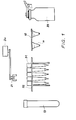
- Fig. 1 shows a schematic representation of the containers and vessels used in an analyzer for determining the properties of body fluids, e.g. blood serum.
- the liquid fed to the analyzer in a sample tube 13 for examination may be too viscous and thus not suitable for processing.
- a number of bottles 33 filled with various diluents are provided in the analyzer.
- the viscous body fluid in the sample tube 13 and the diluent in bottle 33 are mixed in cups 11 arranged in a cup holder 12.
- pipettes 31 are provided held for removal in a pipette tray 32.
- body fluid from the sample tube 13 and diluent from a bottle 33 can be brought to a cup 11 and mixed therein.
- the subject of the invention is the movement and alignment of the pipette tray 32 in a processing station B (see Fig. 3).
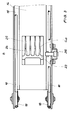
- the device according to the invention consists of an elongate guide trough 14 of U-shaped cross-section extending from an input station formed at the front face of the analyzer to the interior of the apparatus.
- the vertical legs of guide trough 14 are both provided with an outwardly oriented shoulder 15 by means of which one portion of a continuous movement means 16 is slidingly supported.
- the continuous movement means 16 is driven by a microprocessor controlled steppipng motor 17 via pulleys 18.
- the stepping motor 17 is arranged in the housing such that the two continuous movement means 16 each running over a shoulder 15 are driven in synchronism.
- the stepping motor 17 is arranged beneath guide trough 14 and provided with a dual shaft 19 carrying drive pulleys 22.
- a stop member 23 is mounted having a number of stop surfaces 24 associated with the pipettes 31 and being arranged normal to the direction of movement of the continuous movement means 16 and thus to a pipette tray 32.
- the stop surfaces 24 are adapted to the shape of pipettes 31 and located at the end of feed channels 25 separated from one another by thin walls 40 and contribute to the exact alignment of the pipettes 31 in their processing station (see Fig. 3).
- Stop member 23 as well as pipette tray 32 consist of an electrically conductive plastic material in order to remove electrostatic charges via apparatus ground which may produce during transport due to friction occurring between the continuous movement means 16 and the pipette tray 32.
- An optoelectric sensor means 26 is arranged to one side of guide trough 14 in the area of stop member 23 which means is used for exactly aligning the pipettes in processing station B by cooperating with encoding bars 27 formed at the longitudinal rims of a pipette tray 32 and consisting of apertures 28 and partitions 29 (see Fig. 4).
- a return chute 35 starts which is arranged below trough 14 and extends as far as the input station at the front side of the analyser (see Fig. 2A).
- a pipette tray 32 consists of a flat plate 36 having receptacles 37 for pipettes 31.
- the receptacles are arranged in eight rows extending normal to the direction of tray movement. Each row comprises five holes so that a pipette tray 32 can hold 40 pipettes 31 (see Fig. 4).
- plate 36 On both sides, plate 36 is provided with a vertically extending longitudinal wall 38 the height of which is dimensioned such that the pipette tray 32 can be placed on a supporting surface without the pipette ends touching said surface. Plate 36 also features a supporting rim 39 on both sides parallel to the longitudinal wall 38 which supporting rim also comprises the encoding bar 27.
- the device operates as follows:
- the aspirator 20 engages a pipette 31 and pulls it out of the pipette tray 32 in that the tapered proboscis 21 is pressed into an aperture 110 of the pipette which aperture is also tapered.
- the top portion of pipette 31 thereby rests via plate 36 of pipette tray 32 on support surface 41.
- body fluid is removed from sample tube 13 positioned in its processing station and delivered into a cup 11 which is also positioned in its processing station.
- the first used pipette 31 is then thrown into a waste bin and the aspirator 20 removes a second pipette 31 from tray 32 in order to suck diluent from a bottle 33 by means of proboscis 21 and deliver it also to cup 11 filled with body fluid. Repeated aspiration and ejection by the proboscis 21 evenly mixes the fluids to the consistencies desired. As soon as diluted body fluid has been delivered to a dispenser which in turn delivers a predetermined quantity to a slide, the second pipette is also discarded.
Landscapes
- Physics & Mathematics (AREA)
- Health & Medical Sciences (AREA)
- Life Sciences & Earth Sciences (AREA)
- Chemical & Material Sciences (AREA)
- Analytical Chemistry (AREA)
- Biochemistry (AREA)
- General Health & Medical Sciences (AREA)
- General Physics & Mathematics (AREA)
- Immunology (AREA)
- Pathology (AREA)
- Automatic Analysis And Handling Materials Therefor (AREA)
Applications Claiming Priority (2)
| Application Number | Priority Date | Filing Date | Title |
|---|---|---|---|
| DE4023182 | 1990-07-20 | ||
| DE4023182A DE4023182A1 (de) | 1990-07-20 | 1990-07-20 | Vorrichtung zum bewegen von pipettenhalter in einem analysegeraet |
Publications (3)
| Publication Number | Publication Date |
|---|---|
| EP0467285A2 true EP0467285A2 (fr) | 1992-01-22 |
| EP0467285A3 EP0467285A3 (en) | 1992-06-03 |
| EP0467285B1 EP0467285B1 (fr) | 1995-03-22 |
Family
ID=6410730
Family Applications (1)
| Application Number | Title | Priority Date | Filing Date |
|---|---|---|---|
| EP91111834A Expired - Lifetime EP0467285B1 (fr) | 1990-07-20 | 1991-07-16 | Dispositif pour le déplacement d'un support pour pipettes dans un analyseur |
Country Status (4)
| Country | Link |
|---|---|
| EP (1) | EP0467285B1 (fr) |
| JP (1) | JPH04232872A (fr) |
| CA (1) | CA2047072C (fr) |
| DE (2) | DE4023182A1 (fr) |
Families Citing this family (2)
| Publication number | Priority date | Publication date | Assignee | Title |
|---|---|---|---|---|
| JP3677570B2 (ja) * | 1995-10-30 | 2005-08-03 | アークレイ株式会社 | 採液チップ検出方法 |
| JP3733431B2 (ja) * | 1996-07-24 | 2006-01-11 | 東ソー株式会社 | 自動分注装置 |
Family Cites Families (6)
| Publication number | Priority date | Publication date | Assignee | Title |
|---|---|---|---|---|
| DE3246274C2 (de) * | 1981-12-14 | 1985-05-30 | Olympus Optical Co., Ltd., Tokio/Tokyo | Mit immunologischer Agglutinationsreaktion arbeitendes Analysiergerät |
| US4478094A (en) * | 1983-01-21 | 1984-10-23 | Cetus Corporation | Liquid sample handling system |
| US4798095A (en) * | 1986-04-30 | 1989-01-17 | Teruaki Itoh | Apparatus for distributing liquid samples among test tubes and for dividing the test tubes into groups |
| CA1285536C (fr) * | 1987-03-11 | 1991-07-02 | Akihiro Ohoka | Dispositif debiteur |
| JP2761385B2 (ja) * | 1988-04-08 | 1998-06-04 | 東亜医用電子株式会社 | 免疫凝集測定装置 |
| US5008082A (en) * | 1988-08-25 | 1991-04-16 | Eastman Kodak Company | Analyzers using linear sample trays with random access |
-
1990
- 1990-07-20 DE DE4023182A patent/DE4023182A1/de not_active Withdrawn
-
1991
- 1991-07-15 CA CA002047072A patent/CA2047072C/fr not_active Expired - Fee Related
- 1991-07-16 DE DE69108316T patent/DE69108316T2/de not_active Expired - Fee Related
- 1991-07-16 EP EP91111834A patent/EP0467285B1/fr not_active Expired - Lifetime
- 1991-07-19 JP JP3179640A patent/JPH04232872A/ja active Pending
Also Published As
| Publication number | Publication date |
|---|---|
| DE4023182A1 (de) | 1992-01-23 |
| EP0467285B1 (fr) | 1995-03-22 |
| DE69108316D1 (de) | 1995-04-27 |
| DE69108316T2 (de) | 1995-11-02 |
| EP0467285A3 (en) | 1992-06-03 |
| CA2047072A1 (fr) | 1992-01-21 |
| CA2047072C (fr) | 1995-12-05 |
| JPH04232872A (ja) | 1992-08-21 |
Similar Documents
| Publication | Publication Date | Title |
|---|---|---|
| AU577805B2 (en) | Cassette for supporting test tubes of different diameters and/or lengths | |
| CA1230327A (fr) | Methode et dispositif de transport de supports d'eprouvettes scellees et de brassage des echantillons | |
| JP3880658B2 (ja) | 試料ラックおよびそれを移動させる装置並びに方法 | |
| EP0356250B1 (fr) | Analyseurs à arrangement linéaire de supports à accès aléatoire | |
| AU671663B2 (en) | Assay module transport apparatus for use in an automated analytical instrument | |
| US4815978A (en) | Clinical analysis methods and systems | |
| JP6205122B2 (ja) | 検体処理装置 | |
| EP0061317B1 (fr) | Appareil d'échantillonnage | |
| EP3361261A1 (fr) | Dispositif de transfert de porte-échantillons et système d'analyse automatique | |
| JPH09101314A (ja) | 移送装置およびそれを用いた分析装置 | |
| KR20070026335A (ko) | 생물유동체에 관한 분석을 행하는 장치 및 관련방법 | |
| JP2000131329A (ja) | 容器供給のための分析機器用自動サンプルハンドラ― | |
| US5190727A (en) | Device for moving and positioning pipette trays in an analyzer | |
| EP0500506A1 (fr) | Appareil pour immunoessais | |
| CN110873806A (zh) | 运送系统、样本分析装置、样本架、及运送限制方法 | |
| WO1985003571A1 (fr) | Systemes et procedes d'analyse clinique | |
| EP0467285B1 (fr) | Dispositif pour le déplacement d'un support pour pipettes dans un analyseur | |
| JP6913253B2 (ja) | 自動診断分析装置のためのプローブ先端排出デバイスおよびその方法 | |
| EP0523426A2 (fr) | Dispositif pour alimenter en objets une poubelle d'un analyseur | |
| EP0467284B1 (fr) | Dispositif pour le déplacement d'un support pour cuvettes dans un analyseur | |
| CN116840016B (zh) | 一种自动化全血血样制备仪及其工作方法 | |
| CN117280222A (zh) | 容器废弃单元、具备该单元的自动分析装置、以及在自动分析装置中使用过的反应容器的废弃方法 | |
| JP6991335B2 (ja) | 自動診断分析装置のためのプローブ先端廃棄物シュートおよびその方法 | |
| JPH0560766A (ja) | 反応容器自動供給装置 | |
| WO1987006695A1 (fr) | Controle du report d'un diluant |
Legal Events
| Date | Code | Title | Description |
|---|---|---|---|
| PUAI | Public reference made under article 153(3) epc to a published international application that has entered the european phase |
Free format text: ORIGINAL CODE: 0009012 |
|
| AK | Designated contracting states |
Kind code of ref document: A2 Designated state(s): CH DE FR GB LI |
|
| PUAL | Search report despatched |
Free format text: ORIGINAL CODE: 0009013 |
|
| AK | Designated contracting states |
Kind code of ref document: A3 Designated state(s): CH DE FR GB LI |
|
| 17P | Request for examination filed |
Effective date: 19921105 |
|
| 17Q | First examination report despatched |
Effective date: 19940627 |
|
| RBV | Designated contracting states (corrected) |
Designated state(s): DE FR GB |
|
| GRAA | (expected) grant |
Free format text: ORIGINAL CODE: 0009210 |
|
| AK | Designated contracting states |
Kind code of ref document: B1 Designated state(s): DE FR GB |
|
| REF | Corresponds to: |
Ref document number: 69108316 Country of ref document: DE Date of ref document: 19950427 |
|
| ET | Fr: translation filed | ||
| RAP2 | Party data changed (patent owner data changed or rights of a patent transferred) |
Owner name: KODAK AKTIENGESELLSCHAFT Owner name: CLINICAL DIAGNOSTIC SYSTEMS, INC. |
|
| RAP2 | Party data changed (patent owner data changed or rights of a patent transferred) |
Owner name: KODAK AKTIENGESELLSCHAFT Owner name: JOHNSON & JOHNSON CLINICAL DIAGNOSTICS, INC. |
|
| PLBE | No opposition filed within time limit |
Free format text: ORIGINAL CODE: 0009261 |
|
| STAA | Information on the status of an ep patent application or granted ep patent |
Free format text: STATUS: NO OPPOSITION FILED WITHIN TIME LIMIT |
|
| 26N | No opposition filed | ||
| PGFP | Annual fee paid to national office [announced via postgrant information from national office to epo] |
Ref country code: GB Payment date: 19970707 Year of fee payment: 7 |
|
| PGFP | Annual fee paid to national office [announced via postgrant information from national office to epo] |
Ref country code: FR Payment date: 19970709 Year of fee payment: 7 |
|
| PGFP | Annual fee paid to national office [announced via postgrant information from national office to epo] |
Ref country code: DE Payment date: 19970725 Year of fee payment: 7 |
|
| PG25 | Lapsed in a contracting state [announced via postgrant information from national office to epo] |
Ref country code: GB Free format text: LAPSE BECAUSE OF NON-PAYMENT OF DUE FEES Effective date: 19980716 |
|
| GBPC | Gb: european patent ceased through non-payment of renewal fee |
Effective date: 19980716 |
|
| PG25 | Lapsed in a contracting state [announced via postgrant information from national office to epo] |
Ref country code: FR Free format text: LAPSE BECAUSE OF NON-PAYMENT OF DUE FEES Effective date: 19990331 |
|
| PG25 | Lapsed in a contracting state [announced via postgrant information from national office to epo] |
Ref country code: DE Free format text: LAPSE BECAUSE OF NON-PAYMENT OF DUE FEES Effective date: 19990501 |
|
| REG | Reference to a national code |
Ref country code: FR Ref legal event code: ST |