EP0467421A2 - Aérateur de toit - Google Patents
Aérateur de toit Download PDFInfo
- Publication number
- EP0467421A2 EP0467421A2 EP91116720A EP91116720A EP0467421A2 EP 0467421 A2 EP0467421 A2 EP 0467421A2 EP 91116720 A EP91116720 A EP 91116720A EP 91116720 A EP91116720 A EP 91116720A EP 0467421 A2 EP0467421 A2 EP 0467421A2
- Authority
- EP
- European Patent Office
- Prior art keywords
- roof
- outer housing
- shaft
- flaps
- spent air
- Prior art date
- Legal status (The legal status is an assumption and is not a legal conclusion. Google has not performed a legal analysis and makes no representation as to the accuracy of the status listed.)
- Withdrawn
Links
Images



Classifications
-
- F—MECHANICAL ENGINEERING; LIGHTING; HEATING; WEAPONS; BLASTING
- F24—HEATING; RANGES; VENTILATING
- F24F—AIR-CONDITIONING; AIR-HUMIDIFICATION; VENTILATION; USE OF AIR CURRENTS FOR SCREENING
- F24F7/00—Ventilation
- F24F7/02—Roof ventilation
Definitions
- the invention relates to a roof ventilator having a base frame surrounding an upwardly directed shaft in a construction according to the preamble to claim 1.
- the flaps for closing the outlet for the spent air flowing upwards which are pivotable about horizontal axes, project above the outer housing in their open position so that, because of the resulting increased dimensions in height, the ventilator offers a large area exposed to the wind and is exposed to increased loading.
- Pivotable flaps whereby lateral outlets for spent air can be freed or closed are provided for lateral ventilation protected from atmospheric influences.
- the lateral spent-air openings, and hence also their closing flaps have to be designed sufficiently large, which results in minimum dimensions both with regard to equipment width and to equipment height in the known ventilators.
- the known ventilator is a device which is relatively large in construction and therefore relatively heavily stressed by wind and the like.
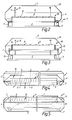
- the roof ventilator numbered in general by 1 in the drawing has a base frame 3 which surrounds an upwardly directed shaft 2 and which - not illustrated in detail - can be secured to the roof of a building for example, bounding a roof opening.
- An outer housing, numbered in general by 4 can be supported on the base frame 3 and bounds an upper outlet 5 for spent air which is situated with spacing above the upper edge of the shaft 2 and substantially coincides with the shaft opening.
- a covering device which is numbered in general by 6 and which has a supporting frame 7 on which louvres 8 arranged parallel side by side are movably supported as closing members in Figures 1 to 4 as well as 12 and 13, and on which flaps 9 which can be swung upwards are movably supported as closing members in the examples of embodiment shown in Figures 7, 8 and 9.
- a drive unit working preferably pneumatically or by means of an electric motor, whereby the louvres 8 or the flaps 9 can be moved out of their respective closed position into their open position.
- the covering device 6 In the open position of the flaps 9 or of the louvres 8, the covering device 6 together with its supporting frame 7 defines a passage which is numbered as a whole by 10 ( Figure 4) and through which, spent air flowing upwards out of the shaft can escape upwards in the direction of the arrow 11 ( Figure 4).
- the examples of embodiment shown in Figures 1 to 9 have a closing unit 16 which is supported in the outer housing 4 for adjustment in height parallel to itself by means of a lifting device 13 and a guiding device 15 comprising a vertical strut 14.
- the closing unit 16, which is movable as a whole, can be transferred, by means of the lifting device 13 into a travel position which is elevated in comparison with its lower end-of-travel position in which it rests on the base frame, and in which the lateral outlets 12 along the longitudinal sides and ends of the supporting frame 7 are freed.
- the lateral outlets 12 are shielded at the top for which purpose the outer housing 4 preferably comprises housing walls, the lower portions of which have a diverging course originating from the base frame 3, along the sides of the shaft opening. These lower portions are followed in each case by middle portions which are aligned substantially vertically. In the example of embodiment shown in Figure 1, these middle portions are followed by upper portions which have an alignment converging towards the upper outlet for the spent air, with such an extent that in the raised travel position of the closing unit 6 and with the lateral outlets 12 freed, ventilation is possible protected from atmospheric influences.
- the present invention additionally provides, inside the outer housing, a housing insert member 17 which, in the raised end-of-travel position of the closing unit 16 with the outlets 12 freed (Figure 6), forms the upper portion of the outer housing wall and at the same time bounds the upper outlet for the spent air, the housing insert member 17 being supported in the outer housing 4 likewise for adjustment in height as a whole by means of a lifting and guiding device 18.
- the housing insert member projects upwards above the upper terminal edges of the outer housing 4. In the lower travel position ( Figure 4), it is situated sunk in the outer housing 4.
- Such an extensible housing insert member 17 likewise offers the advantage, particularly with a covering device 6 comprising flaps 9, of effectively protecting opened flaps and hence their lifting device 13 from wind loading and the like.
Landscapes
- Engineering & Computer Science (AREA)
- Chemical & Material Sciences (AREA)
- Combustion & Propulsion (AREA)
- Mechanical Engineering (AREA)
- General Engineering & Computer Science (AREA)
- Air-Flow Control Members (AREA)
- Glass Compositions (AREA)
- Control Of Motors That Do Not Use Commutators (AREA)
- Massaging Devices (AREA)
- Packages (AREA)
- Solid-Sorbent Or Filter-Aiding Compositions (AREA)
Applications Claiming Priority (2)
| Application Number | Priority Date | Filing Date | Title |
|---|---|---|---|
| DE3841349 | 1988-12-08 | ||
| DE3841349A DE3841349A1 (de) | 1988-12-08 | 1988-12-08 | Dachluefter |
Related Parent Applications (1)
| Application Number | Title | Priority Date | Filing Date |
|---|---|---|---|
| EP89312596.3 Division | 1989-12-01 |
Publications (2)
| Publication Number | Publication Date |
|---|---|
| EP0467421A2 true EP0467421A2 (fr) | 1992-01-22 |
| EP0467421A3 EP0467421A3 (en) | 1992-02-26 |
Family
ID=6368722
Family Applications (2)
| Application Number | Title | Priority Date | Filing Date |
|---|---|---|---|
| EP19910116720 Withdrawn EP0467421A3 (en) | 1988-12-08 | 1989-12-01 | Roof ventilator |
| EP89312596A Expired - Lifetime EP0372874B1 (fr) | 1988-12-08 | 1989-12-01 | Aérateur de toit |
Family Applications After (1)
| Application Number | Title | Priority Date | Filing Date |
|---|---|---|---|
| EP89312596A Expired - Lifetime EP0372874B1 (fr) | 1988-12-08 | 1989-12-01 | Aérateur de toit |
Country Status (3)
| Country | Link |
|---|---|
| EP (2) | EP0467421A3 (fr) |
| AT (1) | ATE87356T1 (fr) |
| DE (2) | DE3841349A1 (fr) |
Families Citing this family (1)
| Publication number | Priority date | Publication date | Assignee | Title |
|---|---|---|---|---|
| CN111380139B (zh) * | 2018-12-29 | 2024-05-28 | 扬州新扬通风设备有限公司 | 一种用于天花吊顶的通风装置 |
Family Cites Families (4)
| Publication number | Priority date | Publication date | Assignee | Title |
|---|---|---|---|---|
| DE1276880B (de) * | 1962-12-18 | 1968-09-05 | Colt Ventilation And Heating L | Dachluefter |
| US3213776A (en) * | 1963-07-03 | 1965-10-26 | Robertson Co H H | Cable operating means for ridge ventilator |
| DE1248263B (de) * | 1965-03-30 | 1967-08-24 | Eberspaecher J | Vorrichtung zur Raumlueftung |
| NZ219383A (en) * | 1986-02-28 | 1988-10-28 | Colt Int Ltd | Roof ventilation device with pivoted flaps |
-
1988
- 1988-12-08 DE DE3841349A patent/DE3841349A1/de not_active Withdrawn
-
1989
- 1989-12-01 EP EP19910116720 patent/EP0467421A3/en not_active Withdrawn
- 1989-12-01 DE DE89312596T patent/DE68905576T2/de not_active Expired - Fee Related
- 1989-12-01 AT AT89312596T patent/ATE87356T1/de not_active IP Right Cessation
- 1989-12-01 EP EP89312596A patent/EP0372874B1/fr not_active Expired - Lifetime
Also Published As
| Publication number | Publication date |
|---|---|
| EP0467421A3 (en) | 1992-02-26 |
| EP0372874A1 (fr) | 1990-06-13 |
| ATE87356T1 (de) | 1993-04-15 |
| DE68905576T2 (de) | 1993-09-30 |
| EP0372874B1 (fr) | 1993-03-24 |
| DE3841349A1 (de) | 1990-06-13 |
| DE68905576D1 (de) | 1993-04-29 |
Similar Documents
| Publication | Publication Date | Title |
|---|---|---|
| US2741972A (en) | Roof jack for ventilating duct | |
| US6582292B1 (en) | Fume hood with rotatable airfoil | |
| US5447468A (en) | Fume hood | |
| US4031819A (en) | Apparatus for collecting and conveying of fumes from a furnace | |
| DE2749924A1 (de) | Lichtbogenschmelzofenanlage | |
| US3213776A (en) | Cable operating means for ridge ventilator | |
| US5688168A (en) | Fume hood with improved counterbalance system | |
| EP0467421A2 (fr) | Aérateur de toit | |
| US4142458A (en) | Energy conserving fume hood | |
| US3760861A (en) | Door for hangars and other structures | |
| US2790377A (en) | Wall cap for ventilating duct | |
| DE59500213D1 (de) | Revisionsvorrichtung für Gebäudewände, insbesondere Brandschutzwände | |
| DE1103433B (de) | Vorrichtung zur Abfuehrung und Umlenkung von durch Gehaeuse und Geraeteschraenke hindurchgeleiteter Kuehlluft | |
| US4081018A (en) | Storm door and screen combination for a garage | |
| US3162720A (en) | Vented pole riser shield | |
| US4410166A (en) | Gas collector for metallurgical vessels | |
| DE2512846A1 (de) | Energieversorgungsstation | |
| FR2536835B1 (fr) | Perfectionnement aux foyers fermes en particulier pour cheminees | |
| CN112022190A (zh) | 一种自屏蔽的ct机 | |
| EP0820955A1 (fr) | Dispositif de ventilation pour cabine d'ascenseur | |
| DE2914475A1 (de) | Einrichtung zur entlueftung und zum rauch- und waermeabzug an gebaeuden | |
| JP2526256Y2 (ja) | スカイハウスのエアカーテン機構 | |
| CN213372057U (zh) | 带电离辐射屏蔽的ct机 | |
| US4462575A (en) | Hood assembly for a metallurgical converter | |
| ATE9260T1 (de) | Stallbelueftung. |
Legal Events
| Date | Code | Title | Description |
|---|---|---|---|
| PUAI | Public reference made under article 153(3) epc to a published international application that has entered the european phase |
Free format text: ORIGINAL CODE: 0009012 |
|
| PUAL | Search report despatched |
Free format text: ORIGINAL CODE: 0009013 |
|
| AC | Divisional application: reference to earlier application |
Ref document number: 372874 Country of ref document: EP |
|
| AK | Designated contracting states |
Kind code of ref document: A2 Designated state(s): AT BE CH DE FR GB IT LI LU NL SE |
|
| AK | Designated contracting states |
Kind code of ref document: A3 Designated state(s): AT BE CH DE FR GB IT LI LU NL SE |
|
| 17P | Request for examination filed |
Effective date: 19920718 |
|
| 17Q | First examination report despatched |
Effective date: 19930813 |
|
| STAA | Information on the status of an ep patent application or granted ep patent |
Free format text: STATUS: THE APPLICATION IS DEEMED TO BE WITHDRAWN |
|
| 18D | Application deemed to be withdrawn |
Effective date: 19940222 |