EP0467427B1 - Trägheitsstossdämpfer für Rotoren - Google Patents
Trägheitsstossdämpfer für Rotoren Download PDFInfo
- Publication number
- EP0467427B1 EP0467427B1 EP91200800A EP91200800A EP0467427B1 EP 0467427 B1 EP0467427 B1 EP 0467427B1 EP 91200800 A EP91200800 A EP 91200800A EP 91200800 A EP91200800 A EP 91200800A EP 0467427 B1 EP0467427 B1 EP 0467427B1
- Authority
- EP
- European Patent Office
- Prior art keywords
- shaft
- vibration damper
- floating housing
- axis
- diameter
- Prior art date
- Legal status (The legal status is an assumption and is not a legal conclusion. Google has not performed a legal analysis and makes no representation as to the accuracy of the status listed.)
- Expired - Lifetime
Links
- 238000013016 damping Methods 0.000 claims description 16
- 229910052751 metal Inorganic materials 0.000 claims description 11
- 239000002184 metal Substances 0.000 claims description 11
- 238000006073 displacement reaction Methods 0.000 claims description 10
- 238000002844 melting Methods 0.000 claims description 4
- 230000000717 retained effect Effects 0.000 claims description 4
- 239000007787 solid Substances 0.000 claims description 4
- 239000007788 liquid Substances 0.000 claims description 3
- WFKWXMTUELFFGS-UHFFFAOYSA-N tungsten Chemical compound [W] WFKWXMTUELFFGS-UHFFFAOYSA-N 0.000 description 9
- 229910052721 tungsten Inorganic materials 0.000 description 9
- 239000010937 tungsten Substances 0.000 description 9
- 238000010521 absorption reaction Methods 0.000 description 3
- 230000008030 elimination Effects 0.000 description 1
- 238000003379 elimination reaction Methods 0.000 description 1
- 238000005096 rolling process Methods 0.000 description 1
Images

Classifications
-
- F—MECHANICAL ENGINEERING; LIGHTING; HEATING; WEAPONS; BLASTING
- F16—ENGINEERING ELEMENTS AND UNITS; GENERAL MEASURES FOR PRODUCING AND MAINTAINING EFFECTIVE FUNCTIONING OF MACHINES OR INSTALLATIONS; THERMAL INSULATION IN GENERAL
- F16F—SPRINGS; SHOCK-ABSORBERS; MEANS FOR DAMPING VIBRATION
- F16F7/00—Vibration-dampers; Shock-absorbers
- F16F7/10—Vibration-dampers; Shock-absorbers using inertia effect
-
- F—MECHANICAL ENGINEERING; LIGHTING; HEATING; WEAPONS; BLASTING
- F16—ENGINEERING ELEMENTS AND UNITS; GENERAL MEASURES FOR PRODUCING AND MAINTAINING EFFECTIVE FUNCTIONING OF MACHINES OR INSTALLATIONS; THERMAL INSULATION IN GENERAL
- F16C—SHAFTS; FLEXIBLE SHAFTS; ELEMENTS OR CRANKSHAFT MECHANISMS; ROTARY BODIES OTHER THAN GEARING ELEMENTS; BEARINGS
- F16C27/00—Elastic or yielding bearings or bearing supports, for exclusively rotary movement
- F16C27/04—Ball or roller bearings, e.g. with resilient rolling bodies
- F16C27/045—Ball or roller bearings, e.g. with resilient rolling bodies with a fluid film, e.g. squeeze film damping
-
- F—MECHANICAL ENGINEERING; LIGHTING; HEATING; WEAPONS; BLASTING
- F16—ENGINEERING ELEMENTS AND UNITS; GENERAL MEASURES FOR PRODUCING AND MAINTAINING EFFECTIVE FUNCTIONING OF MACHINES OR INSTALLATIONS; THERMAL INSULATION IN GENERAL
- F16F—SPRINGS; SHOCK-ABSORBERS; MEANS FOR DAMPING VIBRATION
- F16F15/00—Suppression of vibrations in systems; Means or arrangements for avoiding or reducing out-of-balance forces, e.g. due to motion
- F16F15/02—Suppression of vibrations of non-rotating, e.g. reciprocating systems; Suppression of vibrations of rotating systems by use of members not moving with the rotating systems
- F16F15/023—Suppression of vibrations of non-rotating, e.g. reciprocating systems; Suppression of vibrations of rotating systems by use of members not moving with the rotating systems using fluid means
- F16F15/0237—Suppression of vibrations of non-rotating, e.g. reciprocating systems; Suppression of vibrations of rotating systems by use of members not moving with the rotating systems using fluid means involving squeeze-film damping
-
- F—MECHANICAL ENGINEERING; LIGHTING; HEATING; WEAPONS; BLASTING
- F16—ENGINEERING ELEMENTS AND UNITS; GENERAL MEASURES FOR PRODUCING AND MAINTAINING EFFECTIVE FUNCTIONING OF MACHINES OR INSTALLATIONS; THERMAL INSULATION IN GENERAL
- F16C—SHAFTS; FLEXIBLE SHAFTS; ELEMENTS OR CRANKSHAFT MECHANISMS; ROTARY BODIES OTHER THAN GEARING ELEMENTS; BEARINGS
- F16C2360/00—Engines or pumps
- F16C2360/23—Gas turbine engines
Definitions
- This invention relates to shaft vibration dampers for application in extreme temperature environments which exceed conventional damper capabilities, particularly in gas turbine engines.
- rotor shaft vibrations are commonly controlled by squeeze-film dampers in which the damping medium is an oil film between fixed and floating housings of the damper.
- the damping medium is an oil film between fixed and floating housings of the damper.
- Applications for such dampers are limited to environments where ambient temperature around the damper does not exceed the maximum working temperature of the oil.
- a shaft vibration damper according to this invention is suitable for high-temperature environment applications beyond the range of usual oil film squeeze-film dampers.
- a shaft vibration damper according to this invention is also suitable for cryogenic environments below the temperature capabilities of usual squeeze-film dampers.
- This invention is a new and improved shaft vibration damper including a floating housing on a rotating shaft, a plurality of chambers in the floating housing arranged symmetrically around the axis of rotation of the shaft, and a plurality of impactors in respective ones of the chambers. Vibratory displacement of the shaft and floating housing induces impacts between the impactors and the corresponding chambers which impacts are accompanied by energy-absorbing, local plastic deformation of the impactors and the chambers.
- the chambers are cylindrical bores in the floating housing parallel to the axis of rotation of the shaft and the impactors are cylindrical sleeves, see e.g. prior art document US-A-3 589 782. each having a tungsten rod therein.
- the sleeves are sealed at opposite ends and filled with a damping medium around the tungsten rods which is liquid at damper operating temperature.
- the damping medium is squeezed from between the tungsten rods and the sleeves for additional energy absorption as the impactors engage the chambers.
- a schematically-represented rotor shaft 10 such as a gas turbine engine turbine shaft
- a relatively stationary structure 12 such as an engine casing
- the bearing 14 includes an inner race 18 rotatable with the shaft 10, an outer race 20, and a plurality of rolling elements, i.e., bearing balls 22, between the inner and outer races.
- the centreline of shaft 10 normally coincides with axis 16.
- Dynamic unbalance induces whirling, i.e., deflection of the shaft 10 perpendicular to the axis 16, characterised herein as radial vibratory displacement.
- a vibration damper 24 according to this invention is interposed between the outer race 20 of the bearing 14 and the stationary structure 12 to control radial vibratory displacement of the shaft 10.
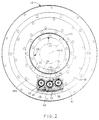
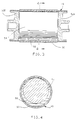
- the shaft vibration damper 24, constructed for laboratory rig testing, includes a floating housing 26 having an annular rim 28, a cylindrical centre support 30, and a perforated radial web 32 between the rim 28 and centre support 30.
- the outer race 20 of the bearing 14 fits closely within the centre support 30 and butts against an internal radial flange 34 of the centre support 30.
- Bolts or other connecting devices, not shown, between the outer race 20 and the radial flange 34 rigidly connect the outer race to the floating housing 26.
- the rim 28 is disposed in a circular aperture 36 in the stationary structure 12.
- An outer radial flange 38 on the rim 28 is held by a retainer 40 bolted to the stationary structure 12.
- the retainer 40 prevents axial movement of the floating housing 26 in the direction of axis 16. Radial clearance, however, between outer flange 38 and the retainer 40 affords the floating housing 26 freedom of movement in a plane perpendicular to axis 16.
- a resilient connection is required between the rim 28 and the stationary structure 12 which is both rigid enough for structural integrity and flexible enough to accommodate radial vibratory displacement of the shaft 10.
- the floating housing 26 further includes a plurality of cylindrical bores, i.e., chambers 42, in the rim 28 each located parallel to the axis 16.
- the chambers 42 are equally angularly spaced around the shaft 10 and are open at their opposite ends through respective ones of a pair of flat sides 44A, 44B of the rim.
- the chambers 42 are surrounded by a pair of seal grooves 45A, 45B in the flat sides 44A, 44B respectively.
- respective ones of a plurality of impactors i.e., damper weights, 46 are disposed in corresponding ones of the chambers 42 and retained therein by a pair of rings 48A, 48B bolted to flat sides 44A, 44B, respectively, of the rim 28.
- a plurality of seals 49 in the grooves 45A, 45B are retained therein by rings 48A, 48B.
- Each impactor 46 includes a cylindrical sleeve 50 the diameter of which is of the order of 0.381 mm (0.015 inches) less than the diameter of the corresponding chamber 42.
- Each sleeve 50 is closed at its opposite ends by a pair of caps 52A, 52B.
- Respective ones of a plurality of solid tungsten rods 54 are disposed in corresponding ones of the sleeves 50 between the caps 52A, 52B.
- the diameters of the tungsten rods 54 are of the order of 0.254 mm (0.010 inches) less than the diameters of the corresponding sleeves 50.
- a high-temperature damping medium 56 fills the clearance between the tungsten rods 54 and the sleeves 50 in each impactor 46.
- the damping medium is liquid at the operating temperature of the damper 24 and may be oil for relatively low-temperature applications and a low-melting temperature metal such as lead for high-temperature applications.
- the sleeves 50 stop moving when they impact the sides of the corresponding chambers 42.
- the tungsten rods 54 continue moving towards the sleeves 50 and, in so doing, squeeze the damping medium 56 from between the rods 54 and the sleeves 50.
- the damping medium 56 absorbs energy and damps the radial vibratory displacement of the shaft 10 in one mode.
- the tungsten rods 54 impact the sleeves 50 and, through the sleeves, the corresponding chambers 42.
- the damper 24 is useful in high and moderate temperature environments.
- the damping medium 56 may be oil.
- the advantage in using the damper 24 with oil is the elimination of piping, seals and the like usually associated with conventional squeeze-film dampers.
- the damping medium 56 may be a low-melting temperature metal such as lead which liquefies within the sleeves 50 as the engine is started.
- the advantage in using a low-melting temperature metal is the significantly higher maximum working temperature achievable.
- the damper 24 may also be useful in low or cryogenic temperature environments such as high-speed pumps in spacecraft propulsion systems which are below the operating temperature range of common oil film squeeze-film dampers.
- a shaft vibration damper could also be constructed for damping in only a single mode. That is, the impactors 46 could be solid so that the only mode of energy absorption is local plastic deformation of the impactors and the corresponding chambers 42 as described above.
Landscapes
- Engineering & Computer Science (AREA)
- General Engineering & Computer Science (AREA)
- Mechanical Engineering (AREA)
- Physics & Mathematics (AREA)
- Acoustics & Sound (AREA)
- Aviation & Aerospace Engineering (AREA)
- Support Of The Bearing (AREA)
- Turbine Rotor Nozzle Sealing (AREA)
- Vibration Prevention Devices (AREA)
Claims (7)
- Ein Vibrationsdämpfer (24) zwischen einer Welle (10), die um eine Drehachse (16) drehbar ist, und einer relativ stationären Struktur (12), wobei der Vibrationsdämpfer (24) ein schwimmendes Gehäuse (26), eine Lagervorrichtung (14), die das schwimmende Gehäuse (26) mit der Welle (10) für deren radiale vibrationsbedingte Verschiebung als eine Einheit mit der Welle in einer Ebene senkrecht zur Drehachse (16) der Welle (10) verbindet, und Rückhaltevorrichtungen (38, 40) umfaßt, die das schwimmende Gehäuse (26) mit der stationären Struktur (12) verbinden und die wirksam die radiale vibrationsbedingte Verschiebung des schwimmenden Gehäuses (26) und der Welle (10) aufnehmen,
dadurch gekennzeichnet,
daß das schwimmende Gehäuse (26) eine Vielzahl von darin ausgebildeten Kammern (42) umfaßt, die symmetrisch um die Drehachse (16) der Welle (10) angeordnet sind,
und daß jede der Kammern (42) einen Auftreffkörper (46) umfaßt, der darin mit einem definierten Spielraum zwischen dem Auftreffkörper (46) und den Wänden der zugehörigen Kammer (42) beweglich zurückgehalten wird, so daß der Auftreffkörper (46) mit den Wänden der zugehörigen Kammer (42) dann zusammenstoßen kann, wenn das schwimmende Gehäuse (26) als eine Einheit mit der Welle (10) vibriert. - Ein Vibrationsdämpfer (24) nach Anspruch 1,
dadurch gekennzeichnet,
daß die Lagervorrichtung (14) einen inneren Laufring (18) umfaßt, der starr mit der Welle (10) verbunden ist, einen äußeren Laufring (20) und eine Vielzahl von Anti-Reibungselementen (22), die zwischen dem inneren Laufring (18) und dem äußeren Laufring (20) liegen, wobei der äußere Laufring (20) starr mit einer zylindrischen Mittelstütze (30) des schwimmenden Gehäuses (26) verbunden ist. - Ein Vibrationsdämpfer (24) nach Anspruch 1 oder 2,
dadurch gekennzeichnet,
daß jede der Kammern (42) eine zylindrische Bohrung im schwimmenden Gehäuse (26) ist, wobei die Bohrung einen ersten Durchmesser hat und im schwimmenden Gehäuse (26) so orientiert ist, daß sich ihre Längsachse parallel zur Drehachse (16) erstreckt,
und daß jede der Auftreffkörper (46) ein Metallzylinder ist, der einen zweiten Durchmesser aufweist, der kleiner als der erste Durchmesser ist. - Ein Vibrationsdämpfer (24) nach Anspruch 3,
dadurch gekennzeichnet,
daß jeder der Auftreffkörper (46) eine zylindrische Metallhülse (50) umfaßt, deren Außendurchmesser genauso groß wie der zweite Durchmesser ist, und einen massiven Metallstab (54), der beweglich innerhalb der Metallhülse (50) zurückgehalten ist und dessen Durchmesser kleiner als der Innendurchmesser der Metallhülse (50) ist. - Ein Vibrationsdämpfer (24) nach Anspruch 4,
dadurch gekennzeichnet,
daß jeder der Auftreffkörper (46) ein dämpfendes Medium (56) enthält, das den massiven Metallstab (54) umgibt und die Metallhülse (50) füllt, wobei das dämpfende Medium (56) bei der normalen Betriebstemperatur des Dämpfers (24) flüssig ist. - Ein Vibrationsdämpfer (24) nach Anspruch 5,
dadurch gekennzeichnet,
daß das dämpfende Medium (56) ein Metall mit niedriger Schmelztemperatur für Hochtemperaturanwendungen des Dämpfers (24) ist. - Ein Vibrationsdämpfer (24) nach Anspruch 6,
dadurch gekennzeichnet,
daß das dämpfende Medium Blei ist.
Applications Claiming Priority (2)
| Application Number | Priority Date | Filing Date | Title |
|---|---|---|---|
| US555222 | 1990-07-20 | ||
| US07/555,222 US5219144A (en) | 1990-07-20 | 1990-07-20 | Mass impact damper for rotors |
Publications (3)
| Publication Number | Publication Date |
|---|---|
| EP0467427A2 EP0467427A2 (de) | 1992-01-22 |
| EP0467427A3 EP0467427A3 (en) | 1992-11-19 |
| EP0467427B1 true EP0467427B1 (de) | 1994-12-07 |
Family
ID=24216460
Family Applications (1)
| Application Number | Title | Priority Date | Filing Date |
|---|---|---|---|
| EP91200800A Expired - Lifetime EP0467427B1 (de) | 1990-07-20 | 1991-04-05 | Trägheitsstossdämpfer für Rotoren |
Country Status (4)
| Country | Link |
|---|---|
| US (1) | US5219144A (de) |
| EP (1) | EP0467427B1 (de) |
| JP (1) | JPH0768996B2 (de) |
| DE (1) | DE69105647T2 (de) |
Families Citing this family (15)
| Publication number | Priority date | Publication date | Assignee | Title |
|---|---|---|---|---|
| NL9301949A (nl) * | 1993-11-10 | 1995-06-01 | Ccm Beheer Bv | Vliegwielenergieopslaginrichting. |
| US6220970B1 (en) * | 1999-11-05 | 2001-04-24 | Ford Global Tech., Inc | Virbration absorption assembly |
| US6439772B1 (en) * | 2000-12-01 | 2002-08-27 | General Electric Company | Method and apparatus for supporting rotor assembly bearings |
| EP1820922A1 (de) * | 2006-02-15 | 2007-08-22 | Dtu | Abgestimmter Flüssigkeitsstoßdämpfer |
| EP2568117A1 (de) * | 2011-09-06 | 2013-03-13 | ALSTOM Technology Ltd | Drehendes Bauteil für eine Strömungsmaschine mit Schwingungsdämpfer, zugehörige Strömungsmaschine und Verwendung eines flüssigen Metalls für einen Schwingungsdämpfer |
| US8443611B2 (en) | 2011-09-09 | 2013-05-21 | General Electric Company | System and method for damping combustor nozzle vibrations |
| CN103267085B (zh) * | 2013-05-07 | 2015-12-23 | 北京化工大学 | 旋转机械转子液力多频动力吸振器 |
| EP3051063B1 (de) * | 2015-01-28 | 2019-10-09 | MTU Aero Engines GmbH | Verstellbare Leitschaufel, zugehörige Turbomaschine und Herstellungsverfahren |
| US10215029B2 (en) * | 2016-01-27 | 2019-02-26 | Hanwha Power Systems Co., Ltd. | Blade assembly |
| DE102016205997A1 (de) * | 2016-04-11 | 2017-10-12 | MTU Aero Engines AG | Leitschaufelsegment |
| DE102016207874A1 (de) * | 2016-05-09 | 2017-11-09 | MTU Aero Engines AG | Impulskörpermodul für eine Strömungsmaschine |
| EP3894665B1 (de) | 2018-12-11 | 2023-07-26 | General Electric Company | Turbinenschaufel |
| US11536144B2 (en) | 2020-09-30 | 2022-12-27 | General Electric Company | Rotor blade damping structures |
| US11739645B2 (en) | 2020-09-30 | 2023-08-29 | General Electric Company | Vibrational dampening elements |
| US12392372B2 (en) * | 2024-01-30 | 2025-08-19 | Miba Industrial Bearings U.S. LLC | Squeeze film damper and a rotating machinery |
Family Cites Families (9)
| Publication number | Priority date | Publication date | Assignee | Title |
|---|---|---|---|---|
| US3589782A (en) * | 1969-09-18 | 1971-06-29 | Westinghouse Electric Corp | Damper bearing to increase rotor stability |
| US4117742A (en) * | 1977-07-29 | 1978-10-03 | Stein Philip C | Permanent automatic rotor balancer for shafts operating above critical speed |
| US4125073A (en) * | 1977-11-09 | 1978-11-14 | Rockwell International Corporation | Impact damping of printing cylinders |
| US4485906A (en) * | 1981-07-31 | 1984-12-04 | Sachs-Systemtechnik Gmbh | Torsional vibration damper, particularly for the clutch disk of a motor vehicle friction disk clutch |
| US4556130A (en) * | 1982-08-30 | 1985-12-03 | Stanley Puszakowski | Vibration damper and method of making the same |
| DE8335470U1 (de) * | 1983-12-10 | 1984-07-05 | Klug, Johann | Schwungrad |
| US4872767A (en) * | 1985-04-03 | 1989-10-10 | General Electric Company | Bearing support |
| JPH0244139U (de) * | 1988-09-21 | 1990-03-27 | ||
| US5056935A (en) * | 1990-11-05 | 1991-10-15 | General Electric Company | Oil film damper seal ring |
-
1990
- 1990-07-20 US US07/555,222 patent/US5219144A/en not_active Expired - Fee Related
-
1991
- 1991-04-05 DE DE69105647T patent/DE69105647T2/de not_active Expired - Fee Related
- 1991-04-05 EP EP91200800A patent/EP0467427B1/de not_active Expired - Lifetime
- 1991-04-25 JP JP3095317A patent/JPH0768996B2/ja not_active Expired - Lifetime
Also Published As
| Publication number | Publication date |
|---|---|
| DE69105647T2 (de) | 1995-04-13 |
| EP0467427A3 (en) | 1992-11-19 |
| JPH0768996B2 (ja) | 1995-07-26 |
| US5219144A (en) | 1993-06-15 |
| DE69105647D1 (de) | 1995-01-19 |
| JPH04249636A (ja) | 1992-09-04 |
| EP0467427A2 (de) | 1992-01-22 |
Similar Documents
| Publication | Publication Date | Title |
|---|---|---|
| EP0467427A2 (de) | Trägheitsstossdämpfer für Rotoren | |
| CN102812261B (zh) | 旋转机器,燃气涡轮发动机及用于旋转机器的阻尼系统 | |
| US3756672A (en) | Shaft damping arrangement | |
| US4084861A (en) | Thrust bearing damping means | |
| JP2709735B2 (ja) | 高速回転軸の流体圧縮膜式ダンパ | |
| US5941133A (en) | Torsional and translational vibration removing device | |
| US3037573A (en) | Shaft vibration dampening | |
| US4527910A (en) | Dual clearance squeeze film damper | |
| Kang et al. | An investigation in stiffness effects on dynamics of rotor-bearing-foundation systems | |
| US4306755A (en) | Gas turbine rotor support systems | |
| US3395949A (en) | Gas-bearing assembly | |
| KR960702075A (ko) | 진동 완충 메커니즘을 가지는 동력 전달 장치 | |
| JP4040875B2 (ja) | モータ軸の同心性を維持することができる遠心機ジャイロダイヤフラム | |
| CN1006181B (zh) | 具有各向异性刚度的轴承 | |
| Cunningham et al. | Design of a squeeze-film damper for a multi-mass flexible rotor | |
| EP0239519B1 (de) | Nutationsdämpfer | |
| US11371581B2 (en) | Torsional vibration damper or torsional tuned mass damper | |
| El-Shafei | Experimental and analytical investigation of hybrid squeeze film dampers | |
| Fleming | Dual clearance squeeze film damper for high load conditions | |
| KR100466904B1 (ko) | 비틀림및병진진동제거장치 | |
| JP3631902B2 (ja) | 振動低減ダンパ | |
| Walton et al. | Rotordynamic Evaluation of an Advanced Multisqueeze Film Damper—Imbalance Response and Blade-Loss Simulation | |
| RU2044936C1 (ru) | Демпфер | |
| Sevencan et al. | Nonlinear vibrations of rotor-bearing systems supported by squeeze film dampers due to unbalance excitation | |
| Earhart | AB Palazzolo¹, J. Moore", J. McElhaney', R. Gadangi' |
Legal Events
| Date | Code | Title | Description |
|---|---|---|---|
| PUAI | Public reference made under article 153(3) epc to a published international application that has entered the european phase |
Free format text: ORIGINAL CODE: 0009012 |
|
| AK | Designated contracting states |
Kind code of ref document: A2 Designated state(s): DE FR GB IT |
|
| PUAL | Search report despatched |
Free format text: ORIGINAL CODE: 0009013 |
|
| AK | Designated contracting states |
Kind code of ref document: A3 Designated state(s): DE FR GB IT |
|
| 17P | Request for examination filed |
Effective date: 19921207 |
|
| 17Q | First examination report despatched |
Effective date: 19940321 |
|
| GRAA | (expected) grant |
Free format text: ORIGINAL CODE: 0009210 |
|
| AK | Designated contracting states |
Kind code of ref document: B1 Designated state(s): DE FR GB IT |
|
| REF | Corresponds to: |
Ref document number: 69105647 Country of ref document: DE Date of ref document: 19950119 |
|
| ITF | It: translation for a ep patent filed | ||
| ET | Fr: translation filed | ||
| PLBE | No opposition filed within time limit |
Free format text: ORIGINAL CODE: 0009261 |
|
| STAA | Information on the status of an ep patent application or granted ep patent |
Free format text: STATUS: NO OPPOSITION FILED WITHIN TIME LIMIT |
|
| 26N | No opposition filed | ||
| PGFP | Annual fee paid to national office [announced via postgrant information from national office to epo] |
Ref country code: DE Payment date: 20010430 Year of fee payment: 11 |
|
| PGFP | Annual fee paid to national office [announced via postgrant information from national office to epo] |
Ref country code: GB Payment date: 20010502 Year of fee payment: 11 |
|
| PGFP | Annual fee paid to national office [announced via postgrant information from national office to epo] |
Ref country code: FR Payment date: 20010518 Year of fee payment: 11 |
|
| REG | Reference to a national code |
Ref country code: GB Ref legal event code: IF02 |
|
| PG25 | Lapsed in a contracting state [announced via postgrant information from national office to epo] |
Ref country code: GB Free format text: LAPSE BECAUSE OF NON-PAYMENT OF DUE FEES Effective date: 20020405 |
|
| PG25 | Lapsed in a contracting state [announced via postgrant information from national office to epo] |
Ref country code: DE Free format text: LAPSE BECAUSE OF NON-PAYMENT OF DUE FEES Effective date: 20021101 |
|
| GBPC | Gb: european patent ceased through non-payment of renewal fee |
Effective date: 20020405 |
|
| PG25 | Lapsed in a contracting state [announced via postgrant information from national office to epo] |
Ref country code: FR Free format text: LAPSE BECAUSE OF NON-PAYMENT OF DUE FEES Effective date: 20021231 |
|
| REG | Reference to a national code |
Ref country code: FR Ref legal event code: ST |
|
| PG25 | Lapsed in a contracting state [announced via postgrant information from national office to epo] |
Ref country code: IT Free format text: LAPSE BECAUSE OF NON-PAYMENT OF DUE FEES;WARNING: LAPSES OF ITALIAN PATENTS WITH EFFECTIVE DATE BEFORE 2007 MAY HAVE OCCURRED AT ANY TIME BEFORE 2007. THE CORRECT EFFECTIVE DATE MAY BE DIFFERENT FROM THE ONE RECORDED. Effective date: 20050405 |