EP0467573A2 - Appareil de fond de puits actionné par pression - Google Patents
Appareil de fond de puits actionné par pression Download PDFInfo
- Publication number
- EP0467573A2 EP0467573A2 EP91306198A EP91306198A EP0467573A2 EP 0467573 A2 EP0467573 A2 EP 0467573A2 EP 91306198 A EP91306198 A EP 91306198A EP 91306198 A EP91306198 A EP 91306198A EP 0467573 A2 EP0467573 A2 EP 0467573A2
- Authority
- EP
- European Patent Office
- Prior art keywords
- well
- conduit
- bore
- wall
- tubular conduit
- Prior art date
- Legal status (The legal status is an assumption and is not a legal conclusion. Google has not performed a legal analysis and makes no representation as to the accuracy of the status listed.)
- Withdrawn
Links
Images


Classifications
-
- E—FIXED CONSTRUCTIONS
- E21—EARTH OR ROCK DRILLING; MINING
- E21B—EARTH OR ROCK DRILLING; OBTAINING OIL, GAS, WATER, SOLUBLE OR MELTABLE MATERIALS OR A SLURRY OF MINERALS FROM WELLS
- E21B33/00—Sealing or packing boreholes or wells
- E21B33/10—Sealing or packing boreholes or wells in the borehole
- E21B33/12—Packers; Plugs
- E21B33/129—Packers; Plugs with mechanical slips for hooking into the casing
- E21B33/1295—Packers; Plugs with mechanical slips for hooking into the casing actuated by fluid pressure
-
- E—FIXED CONSTRUCTIONS
- E21—EARTH OR ROCK DRILLING; MINING
- E21B—EARTH OR ROCK DRILLING; OBTAINING OIL, GAS, WATER, SOLUBLE OR MELTABLE MATERIALS OR A SLURRY OF MINERALS FROM WELLS
- E21B23/00—Apparatus for displacing, setting, locking, releasing or removing tools, packers or the like in boreholes or wells
- E21B23/04—Apparatus for displacing, setting, locking, releasing or removing tools, packers or the like in boreholes or wells operated by fluid means, e.g. actuated by explosion
- E21B23/042—Apparatus for displacing, setting, locking, releasing or removing tools, packers or the like in boreholes or wells operated by fluid means, e.g. actuated by explosion using a single piston or multiple mechanically interconnected pistons
-
- E—FIXED CONSTRUCTIONS
- E21—EARTH OR ROCK DRILLING; MINING
- E21B—EARTH OR ROCK DRILLING; OBTAINING OIL, GAS, WATER, SOLUBLE OR MELTABLE MATERIALS OR A SLURRY OF MINERALS FROM WELLS
- E21B23/00—Apparatus for displacing, setting, locking, releasing or removing tools, packers or the like in boreholes or wells
-
- E—FIXED CONSTRUCTIONS
- E21—EARTH OR ROCK DRILLING; MINING
- E21B—EARTH OR ROCK DRILLING; OBTAINING OIL, GAS, WATER, SOLUBLE OR MELTABLE MATERIALS OR A SLURRY OF MINERALS FROM WELLS
- E21B23/00—Apparatus for displacing, setting, locking, releasing or removing tools, packers or the like in boreholes or wells
- E21B23/04—Apparatus for displacing, setting, locking, releasing or removing tools, packers or the like in boreholes or wells operated by fluid means, e.g. actuated by explosion
-
- E—FIXED CONSTRUCTIONS
- E21—EARTH OR ROCK DRILLING; MINING
- E21B—EARTH OR ROCK DRILLING; OBTAINING OIL, GAS, WATER, SOLUBLE OR MELTABLE MATERIALS OR A SLURRY OF MINERALS FROM WELLS
- E21B23/00—Apparatus for displacing, setting, locking, releasing or removing tools, packers or the like in boreholes or wells
- E21B23/04—Apparatus for displacing, setting, locking, releasing or removing tools, packers or the like in boreholes or wells operated by fluid means, e.g. actuated by explosion
- E21B23/0411—Apparatus for displacing, setting, locking, releasing or removing tools, packers or the like in boreholes or wells operated by fluid means, e.g. actuated by explosion specially adapted for anchoring tools or the like to the borehole wall or to well tube
-
- E—FIXED CONSTRUCTIONS
- E21—EARTH OR ROCK DRILLING; MINING
- E21B—EARTH OR ROCK DRILLING; OBTAINING OIL, GAS, WATER, SOLUBLE OR MELTABLE MATERIALS OR A SLURRY OF MINERALS FROM WELLS
- E21B23/00—Apparatus for displacing, setting, locking, releasing or removing tools, packers or the like in boreholes or wells
- E21B23/04—Apparatus for displacing, setting, locking, releasing or removing tools, packers or the like in boreholes or wells operated by fluid means, e.g. actuated by explosion
- E21B23/0412—Apparatus for displacing, setting, locking, releasing or removing tools, packers or the like in boreholes or wells operated by fluid means, e.g. actuated by explosion characterised by pressure chambers, e.g. vacuum chambers
-
- E—FIXED CONSTRUCTIONS
- E21—EARTH OR ROCK DRILLING; MINING
- E21B—EARTH OR ROCK DRILLING; OBTAINING OIL, GAS, WATER, SOLUBLE OR MELTABLE MATERIALS OR A SLURRY OF MINERALS FROM WELLS
- E21B34/00—Valve arrangements for boreholes or wells
- E21B34/06—Valve arrangements for boreholes or wells in wells
-
- E—FIXED CONSTRUCTIONS
- E21—EARTH OR ROCK DRILLING; MINING
- E21B—EARTH OR ROCK DRILLING; OBTAINING OIL, GAS, WATER, SOLUBLE OR MELTABLE MATERIALS OR A SLURRY OF MINERALS FROM WELLS
- E21B34/00—Valve arrangements for boreholes or wells
- E21B34/06—Valve arrangements for boreholes or wells in wells
- E21B34/063—Valve or closure with destructible element, e.g. frangible disc
-
- E—FIXED CONSTRUCTIONS
- E21—EARTH OR ROCK DRILLING; MINING
- E21B—EARTH OR ROCK DRILLING; OBTAINING OIL, GAS, WATER, SOLUBLE OR MELTABLE MATERIALS OR A SLURRY OF MINERALS FROM WELLS
- E21B34/00—Valve arrangements for boreholes or wells
- E21B34/06—Valve arrangements for boreholes or wells in wells
- E21B34/066—Valve arrangements for boreholes or wells in wells electrically actuated
-
- E—FIXED CONSTRUCTIONS
- E21—EARTH OR ROCK DRILLING; MINING
- E21B—EARTH OR ROCK DRILLING; OBTAINING OIL, GAS, WATER, SOLUBLE OR MELTABLE MATERIALS OR A SLURRY OF MINERALS FROM WELLS
- E21B34/00—Valve arrangements for boreholes or wells
- E21B34/06—Valve arrangements for boreholes or wells in wells
- E21B34/10—Valve arrangements for boreholes or wells in wells operated by control fluid supplied from outside the borehole
- E21B34/102—Valve arrangements for boreholes or wells in wells operated by control fluid supplied from outside the borehole with means for locking the closing element in open or closed position
-
- E—FIXED CONSTRUCTIONS
- E21—EARTH OR ROCK DRILLING; MINING
- E21B—EARTH OR ROCK DRILLING; OBTAINING OIL, GAS, WATER, SOLUBLE OR MELTABLE MATERIALS OR A SLURRY OF MINERALS FROM WELLS
- E21B41/00—Equipment or details not covered by groups E21B15/00 - E21B40/00
-
- E—FIXED CONSTRUCTIONS
- E21—EARTH OR ROCK DRILLING; MINING
- E21B—EARTH OR ROCK DRILLING; OBTAINING OIL, GAS, WATER, SOLUBLE OR MELTABLE MATERIALS OR A SLURRY OF MINERALS FROM WELLS
- E21B43/00—Methods or apparatus for obtaining oil, gas, water, soluble or meltable materials or a slurry of minerals from wells
- E21B43/11—Perforators; Permeators
- E21B43/116—Gun or shaped-charge perforators
- E21B43/1185—Ignition systems
-
- E—FIXED CONSTRUCTIONS
- E21—EARTH OR ROCK DRILLING; MINING
- E21B—EARTH OR ROCK DRILLING; OBTAINING OIL, GAS, WATER, SOLUBLE OR MELTABLE MATERIALS OR A SLURRY OF MINERALS FROM WELLS
- E21B43/00—Methods or apparatus for obtaining oil, gas, water, soluble or meltable materials or a slurry of minerals from wells
- E21B43/11—Perforators; Permeators
- E21B43/116—Gun or shaped-charge perforators
- E21B43/1185—Ignition systems
- E21B43/11852—Ignition systems hydraulically actuated
-
- E—FIXED CONSTRUCTIONS
- E21—EARTH OR ROCK DRILLING; MINING
- E21B—EARTH OR ROCK DRILLING; OBTAINING OIL, GAS, WATER, SOLUBLE OR MELTABLE MATERIALS OR A SLURRY OF MINERALS FROM WELLS
- E21B47/00—Survey of boreholes or wells
- E21B47/12—Means for transmitting measuring-signals or control signals from the well to the surface, or from the surface to the well, e.g. for logging while drilling
- E21B47/14—Means for transmitting measuring-signals or control signals from the well to the surface, or from the surface to the well, e.g. for logging while drilling using acoustic waves
- E21B47/18—Means for transmitting measuring-signals or control signals from the well to the surface, or from the surface to the well, e.g. for logging while drilling using acoustic waves through the well fluid, e.g. mud pressure pulse telemetry
- E21B47/24—Means for transmitting measuring-signals or control signals from the well to the surface, or from the surface to the well, e.g. for logging while drilling using acoustic waves through the well fluid, e.g. mud pressure pulse telemetry by positive mud pulses using a flow restricting valve within the drill pipe
Definitions
- the present invention relates to subsurface well apparatus and more particularly to the remote operation of subterranean well tools.
- Subsurface well tools have been operated in the past by a wide variety of mechanisms.
- Manipulation of the tubing string such as push and/or pull, tubular rotation, and the like, is one of the more common methods employed, but can be difficult to accurately accomplish in deep or deviated wells.
- Other actuation means include use of hydraulic/hydrostatic members, pneumatic elements, as well as radio and other surface and subsurface-initiated electronic components.
- Typical of subterranean well tools actuated by such procedures include bridge plugs, packers, perforating guns, tubing hangers, safety and other valves, test trees, and the like, all of which are contemplated for use with the present invention.
- Such tools require actuation procedures, such as setting at correct depth in the well and at a particular time during the completion operation, unsetting in response to a given well condition or event, re-setting, opening, closing or throttling flow paths, perforating casing, and the like.
- Seals that are employed in and between operating components of well tools, such as pistons and housings therefor, are subject to deterioration, hence leakage, because of the high temperature, high pressure environment in which such seals are required to operate regardless of whether such seals are elastomeric, metallic, or any other commonly used structures. This is particularly true of the seals employed on actuating pistons for packers, safety valves or similar downhole tools wherein an actuating fluid is applied to one side of the piston and the other side of the piston is exposed to well fluids, atmospheric pressure, or the like.
- the downhole source of energy is an explosive charge which is discharged and the resulting gas is applied to a piston which functions to set a hanger in a well casing.
- the triggering signals for energizing the downhole circuitry for effecting the discharge of the explosive charge is produced by a pair of sonic frequency generators which are located at the surface and which are transmitted downhole through well fluids or a tubing string, or can be packaged with a suitable power supply container that is lowered into the well on wireline or cable.
- U.S. Patent No. 4,896,722 discloses another approach to energization of a downhole source of energy.
- the hydrostatic pressure of well fluids in the well annulus acts on a floating piston to provide the source of downhole energy.
- Such energy is employed to effect the opening and closing of a test valve which is normally utilized in the lower end of a string of drill stem testing tools.
- the hydrostatically pressurized oil acts on one side of a piston which is opposed on its opposite side by air at atmospheric or other low pressure.
- the piston is prevented from movement by a spring until a predetermined hydrostatic annulus pressure is obtained.
- a pair of solenoid controlled valves controls the hydrostatic pressure acting on the floating piston.
- the two solenoid control valves are in turn controlled by a microprocessor which operates in response to a pressure transducer which is exposed to annulus pressure and provides an electrical signal output indicative thereof.
- the signals applied to the pressure transducer are in the nature of a series of low level pressure pulses, each having a specified duration. Such pulses are applied at the well surface to the fluids standing in the well annulus.
- the detection circuitry which picks up the signals is complicated because it has to be designed to respond to only a specific series of low level pressure pulses.
- the prior art has not provided an actuating system for a downhole well tool which does not require ports in the production tubing or work string or component in fluid communication therewith, and which may be reliably controlled from the surface through the utilization of control forces through the wall of the production tubing or work string to produce an activating signal for actuating the downhole well tool by a downhole energy source and to block fluid communication between an actuating fluid body and a second fluid source within said well across dynamic seals between actuating members of the well tool.
- the method and apparatus of this invention may be employed for the actuation of any one or more downhole tools, such as packers, safety valves, testing valves, perforating guns, and the like.
- the apparatus employed in the invention contemplates a production tubing or work string portion extendable to a tubular conduit string extending from the earth surface down into contact with the well fluids existing in the well.
- the wall of such production tubing is imperforate throughout its entire length and to and through the actuating members of the well tool or tools to be actuated.
- the apparatus and method block fluid communication between an activating fluid body and a second fluid source within the well across dynamic seals between the actuating members of the well tool during actuation thereof.
- the apparatus and method of the present invention also contemplate incorporation of a signal generating means which forms a part of the wall of the tubular conduit portion for selectively generating a signal in response to a predetermined condition which is detectable on the wall of the conduit string or portion.
- Actuation means are disposed exteriorly of the bore of the production conduit and include an actuating member for performing at least one desired function.
- An activating body is in direct or indirect communication with the actuating member.
- Movement prevention means selectively resist movement of the actuating member.
- releasing means are responsive to the signal generating means for releasing the movement prevention means from the actuating member for performance of the desired function or functions, and the apparatus thus prevents direct fluid communication between the activating fluid and the second fluid source across the seals.
- a packer which may be incorporated with this invention may be mounted in surrounding relationship to the production tubing or work string and actuated by the downhole apparatus of this invention to sealingly engage the bore wall of the well casing.
- the signaling generating means preferably comprises a strain gauge forming a part of the imperforate wall of the production tubing, but may also be a piezo electric crystal, light beam, sonic vibratory component, or any other non-magnetic transducer or electronically activated element which generates a signal which is detectable as hereinafter described and contemplated.
- the strain gauge, or other element is mounted so as to detect all forms of stress or other physical phenomena (hence, strain) detectable on the wall portion.
- a first signal may be produced in response to a preselected circumferential tensile stress, a different signal in response to a preselected circumferential compressive stress, or other signals respectively corresponding to the existence of predetermined strain in the wall portion of the production tubing or work string portion to which the strain gauge is affixed.
- such changes in average value of the resistance of the strain gauge are detected by a conventional electronic hookup to a microprocessor (shown only schematically in the drawings and not forming a part of the inventive concept per se).
- the average value changes are amplified to a level sufficient to effect the activation of a stored or other energy actuating mechanism which may take a variety of forms, such as an explosive charge which is fired to generate a high pressure gas, a spring, or a motor, which is then employed to shift a piston or other mechanism, to effect the actuation of a well tool, for example, a packer.
- the control signal could also be employed to operate one or more solenoid valves to derive energy from the hydrostatic annulus pressure to effect the opening or closing of a testing valve or safety valve.
- control signal can be employed to function as a latch release means for a downhole tool actuating piston disposed in a chamber formed exteriorly of the production conduit and containing pressurized gas either generated in-situ, or stored, or explosively created, urging the piston or other activating mechanism in a tool operating direction. So long as the latch mechanism is engaged with the piston, or the like, the tool is not operable, but the control signal is applied to a solenoid to release the latch, thus releasing the piston for movement to effect the actuation of the tool.
- such tool may conveniently comprise a packer which is set by the release of the latch in response to a predetermined change in strain in that portion of the production conduit on which the strain gauge is mounted.
- the packer When the packer is set, other signals may be generated for various useful purposes.
- the setting of the packer will, for example, effect a substantial reduction in the axial tensile stress existing in the conduit above the packer. If the strain gauge is so located, it will generate a significant in-situ signal which can be sent to the surface by an acoustic or radio frequency transmitter to inform the operator that the packer or other downhole tool has indeed been set, or activated.
- the second signal generated by the strain gauge upon or at any time subsequent to the setting of the packer can be utilized to effect the firing of a perforating gun or other activation of a second or auxiliary well tool.
- the perforating gun be fired when the pressure conditions in the production zone below the packer are in a so-called "underbalanced" condition, where the fluid pressure within the production conduit is significantly less than the annulus fluid pressure.
- This reduction in production tubing pressure may be conventionally accomplished by running the production tubing or work string into the well dry by having a closed valve at its lower end, or by swabbing any fluids existing in the production tubing or work string from the well after the packer is set. This procedure has many variables and such procedure and variables are well known to those skilled in the art. In either event, the resulting change in circumferential compressive stress will result in the strain gauge producing a distinctive signal which may be employed to effect the firing of the perforating gun.
- the perforating gun After the firing of the perforating gun, it is common to kill the well, unset the packer, retrieve the work string and run into the well a permanent completion hook-up, including, for example, a safety valve, a packer, a production screen, or ported sub, and the like.
- the production string is positioned in the well so as to place the screen, or ported sub, to lie adjacent the newly formed perforations in the casing, thus permitting production fluid to flow through the screen or ported sub and into the production tubing.
- test valve If a test valve is incorporated in the lower portion of the production tubing, it can be maintained in a closed position by a spring or other means, and conventional instrumentation disposed within the production tubing can effect a measurement of the formation pressure.
- An increase in fluid pressure within the production tubing over the annulus fluid pressure will result in a circumferential compressive stress, in the strain gauge accompanied by a significant change in the resistance of the strain gauge in the circumferential direction.
- This signal can be employed to effect the opening of the testing valve or safety valve as the case may be, by a solenoid winding disposed in surrounding relation to the production tubing.
- solenoid operated testing valves and/or safety valves are well known in the art.
- the electrical energy for operating the various solenoids heretofore referred to is preferably supplied by a downhole battery pack which is disposed in the annulus surrounding the production tubing string.
- Fig. 1 is a schematic, vertical sectional view of a well showing a tubing string incorporating a packer, a safety valve, and a perforating gun positioned in the well subsequent to setting of the packer in response to signals generated by a strain gauge forming a portion of the wall of the production conduit.
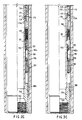
- Figs. 2A, 2B and 2C collectively represent an enlarged scale, vertical sectional view of the unset packer and packer actuating mechanism, including a schematic showing of the strain gauge and microprocessor employed for setting the packer and actuating other well tools.
- Figs. 3A, 3B and 3C respectively correspond to Figs. 2A, 2B and 2C but show the position of the packer and its actuating mechanism after the setting of the packer has been accomplished.
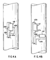
- Figs. 4A and 4B schematically illustrate alternative connections to strain gauges to detect changes in axial and/or circumferential stresses in a production conduit.
- a wellhead 11 conventional in nature, securing a production conduit 12 extending from the lowermost facial side of the wellhead 11 into a subterranean well 10.
- the production conduit 12 may be production tubing, or a tubular work string, conventional in nature, and well known to those skilled in the art.
- the production conduit 12 is shown as carrying a safety valve 13, which may take the form of a ball, flapper, or other valve construction known to those skilled in the art.
- a packer 14 is schematically illustrated as being disposed on the production conduit 12 below the safety valve 13, with the conduit, 12 extending in the well 10 and within casing 15.
- Actuation controls 16 depicted in more detail in Figs. 2B, 2C, 3B, and 3C, are disposed on the well conduit 12 below the packer 14.
- a well production screen 17 is shown on the conduit 12 above a perforating gun 18. It will be appreciated by those skilled in the art that, in lieu of a screen 17, a simple ported sub may be utilized for introduction of production fluids from the production zone PZ of the well 10 into the annular area between the casing 15 and production conduit 12, thence interiorly of the conduit 12 to the top of the wellhead 11.
- the perforating gun 18 is shown as a tubing-conveyed perforating gun which is well known to those in well completion technology.
- the apparatus of the present invention is shown disposed within the casing 15 with the packer 14 being positioned in unset mode.
- the production conduit 12 extends to a conduit member, or body 142, having threads 141 at its uppermost end for securement to companion threads in the lowermost section of the production conduit 12 thereabove.
- the lower end of body 142 and an upper end of member 19 are inter-engaged via screw-threads 143.
- a securing ring 144 is carried around the exterior of the body 142 for containment of the uppermost end of a series of slip members 145 having contoured teeth 146 circumferentially subscribed exteriorly therearound for embedding and anchoring engagement fo the packer 14 relative to the casing 15 when the tool is shown in the set position, as in Figs. 3A, 3B, and 3C.
- the slips 145 have a lower facing beveled slip ramp 150 for companion interface with a ramp 149 carried at the uppermost end of an upper cone member 148 being carried exteriorly around a support member 146A, with the upper cone 148 secrued to the support 146A by means of shear pin members 147.
- the slips are secured in retracted position relative to the cone 148, prior to setting actuation.
- non-extrusion seal members which may comprise a combination of metallic and elastomeric seal assemblies, the seal system 151 being carried exteriorly around the cone 148.
- the system 151 is affixed around the exterior of the body 142 and at the uppermost end of a conventional elastomeric seal element 152 having an upper inward lip 152A extending interiorly of the seal system 151.
- a lower lip 152B of similar construction as the lip 152A.
- a second, or lower, non-extrusion seal system 151 which, in turn, is carried around its lowermost end on the uppermost beveled face of the lower cone element 153 which is shear pinned at pin 154 to the body 142.
- a lower ramp 155 is carried exteriorly around the cone 153 and contoured interiorly at its lowermost tip for companion interengagement with a similarly profiled slip ramp 156 around the uppermost interior surface of the slip element 157.
- the lower slip 157 has teeth 158 which are similar in construction to the teeth 146 on the uppermost slip rings or elements 145 for interengagement to anchor the device relative to the casing member 15 when the tool is in the set position, as shown in Fig. 3A.
- a body lock ring 160 which is housed exteriorly of the body 142 and interior of an outer ring 162.
- the ring 160 is provided with ratchet teeth 159 on its interior surface which ratchet against the body 142.
- the purpose of the body lock ring 160 is to lock the setting force caused by upward movement of the outer ring portion 161 into the slips 157 and expanded seal element 152 so that these members do not return to the unset position once the setting force is removed.
- a series of threads 143 for securing the body 142 to the tubular member 19 extending to the actuation controls 16, shown in Figs. 2B and 2C.
- the actuating sleeve 162 extends to the outer ring portion 161 (Fig. 2A) at its uppermost end and is secured at threads 163 (Fig. 2B) to a piston mandrel 164.
- the inside of piston mandrel 164 has a series of elastomeric or metallic seal members 166 to prevent fluid communication between the piston mandrel 164 and the member 19, that is, to provide a fluid seal between piston mandrel 164 and member 19.
- piston mandrel 164 At the lowermost end of the piston mandrel 164 is an enlarged piston head 165 having seal members 165a thereon.
- the piston mandrel 164 is secured by threads 169 to a lock sleeve 191 which has at its lowermost end (Fig. 2C) a locking dog 177 secured in place within a groove 178 profiled in the member 19 to prevent relative movement between the lock sleeve 191 and the member 19 prior to actuation, as discussed below.
- piston head 165 Above the piston head 165 is an atmospheric chamber 168 which extends between the seal members 167 and 165a.
- Nitrogen is emplaced in the chamber 171 through a filler passage 172 which is capped at 173 subsequent to the filling procedure which is performed prior to introduction of the apparatus into the well.
- a cylinder housing 170 is secured by threads 173B at its uppermost end to a ring member 166A and by threads 173A to an actuator housing 174 therebelow.
- Seal 167 occupies a groove around the outside of ring member 166A and provides a seal between the ring member 166A and the cylinder housing 170 which is secured to it.
- Another seal 167A occupies a groove around the ineide of ring member 166A and slidingly engages piston mandrel 164. Comparing Figs. 2B and 3B, it can be seen that piston mandrel 164 and outer ring 162 are moved, but not cylinder housing 170, nor ring member 166A.
- the nitrogen chamber 171 is defined between the seals 165a in the piston head 165 and a series of similar seals 175 in the cylinder housing 170.
- a master control spring 176 housed within the actuator housing 174 at its uppermost end and the cylinder housing 170 is a master control spring 176 carried above a spring housing 179, exteriorly of lock sleeve 191.
- a non-magnetic solenoid member 180 of conventional construction, which is secured above a ferro-magnetic core member 181.
- the solenoid member 180 is in communication electronically with a strain gauge 183 through a microprocessor 185 by means of circuit lines 182, 182a.
- the strain gauge 183 is secured to the outer wall of the member 19, such that the given condition on the wall of the conduit member 19 is sensed by the gauge 183.
- a microprocessor 185 which may be pre-programmed prior to introduction of the apparatus into the well to detect and generate instructions relative to the solenoid member 180 and the strain gauge 183 in known fashion.
- a battery 187 provides electrical energy through lines 186 to the microprocessor 185.
- the cylindrical housing 170 is secured at threads 188 to a lower sub 189 which, in turn, is secured by threads 190 to another short section of production tubing, or the like, or may be simply bull-plugged and thus defining the lowermost end of the production conduit 12.
- an auxiliary tool may be disposed below the actuation controls 16, such as the perforating gun 18.
- the downhole signal generating means embodying this invention comprises a strains gauge 400 applied to the wall of the production conduit which will change its resistance in response to significant changes in the stresses existing in the conduit wall to which it is attached.
- Strain gauge 400 may be a rectangular configuration as shown in Fig. 4A with connectors 400a, 400b, 400c and 400d respectively connected to the mid points of each side of the strain gauge 400.
- connectors 400a and 400c will detect changes in resistance due to changes in axial stress in the conduit.
- Connectors 400b and 400d will detect changes in resistance due to changes in circumferential stress in the conduit.
- Connectors 400a, 400b, 400c and 400d thus provide signal inputs to the microprocessor 410 which will generate an activating voltage for operating a downhole tool, such as the packer 14.
- the second strain gauge 402 is circumferentially secured to the conduit and has connectors 400b and 400d secured to its opposite ends to indicate axial stresses in the conduit.
- the apparatus of the present invention is run into the well interior of the casing 15 and below the wellhead 11, with the production conduit 12 carrying well tools, such as the safety valve 13, packer 14, screeen 17 and perforating gun 18.
- the actuation controls 16 are shown in Fig. 1 positioned below the packer 14 on the production conduit 12. However, it will be appreciated that such a control 16 may be positioned either above or below the packer 14, or other well tool on the production conduit 12.
- the production conduit 12 may either be set down, picked up, or rotated, either clockwise or counterclockwise.
- the microprocessor 185 has been pre-programmed to detect a predetermined sequence of strain caused thereby, which is, in turn, detected by the strain gauge 183.
- the battery 187 delivers energy power through line 186 to the microprocessor 185 which, in turn, governs the strain gauge 183.
- a signal is sent through line 182 to the magnetic solenoid member 180 which, in turn, actuates a trigger to shift the spring housing 179 upwardly such that the locking dog 177 may move out of the groove 178 of the lock sleeve 191 into a recess 179A in the spring housing 179.
- Spring housing 179 also raises the control spring 176 to act as a booster upon the piston head 165.
- the energy in the nitrogen chamber 171 moves the piston head 165 against the atmospheric chamber 168 to urge the piston mandrel 164 upwardly and move the sleeve 162 upwardly such that the lower slip 157 moves on the ramp 155 to urge the teeth 158 of the lower slip 157 out into biting engagement with the internal wall of the casing 15.
- the energy transmitted through the actuation of the piston head 165 is transmitted such that the upper cone 148 moves upwards relative to the upper slips 145 to permit the teeth 146 of the upper slip 145 to engage the casing 15.
- the seal element 152 is compressed and the seals 151, 152 move into sealing engagement with the interior wall of the casing 15.
- the lock ring 160 ratchets relative to the body 142 to secure the packer actuation in place.
- the actuation controls 16 have a member 19 thereon which is not ported, such that the dynamic seals 165a, 166 do not come into fluid communication with the fluid either in the atmospheric chamber 168 or in the interior of the production conduit 12, nor do such seals contact or communicate directly with fluid in the annulus between the casing 15 and the production conduit 12.
- the seals 165a seal the atmospheric chamber 168 from the nitrogen chamber 171.
- the claims include language directed to a tubular conduit having an "imperforate" wall extending from the surface to a point downhole.
- Prior art setting tools are known which used either (1) physical manipulation of the tubular conduit such as pushing or pulling and; (2) hydraulic fluid pressure within the interior of the tubular conduit.
- the hydraulically operated tools tended to have one or more ports provided between the interior of the tubing string and the piston mechanism which moved to set the slips and packer.
- the present actuating system is an improvement in that the actuating mechanism is entirely on the exterior of the tubular conduit, thereby eliminating potential leak paths and seal problems of the type experienced in the past with ported tubular conduits which allowed communication between the interior of the tubular conduit and the actuating mechanism.
- the strain gauges which are mounted exteriorly of the tubular conduit, are actually placed inside an atmospheric chamber. Therefore, the internal pressure within the tubular conduit (absolute pressure) acts against the atmospheric chamber to strain the tubing.
- the strain gauges are not actually placed so as to measure a difference between annulus fluid pressure and conduit bore fluid pressure, in the strictest sense. In other words, the measurement is an absolute measurement relative to the atmospheric chamber.
- the predetermined change in strain in the wall portion of the tubular body is actually produced by a predetermined difference between conduit bore fluid pressure and a reference pressure exterior to the bore of the tubular body.
Landscapes
- Engineering & Computer Science (AREA)
- Life Sciences & Earth Sciences (AREA)
- Mining & Mineral Resources (AREA)
- Geology (AREA)
- Physics & Mathematics (AREA)
- Environmental & Geological Engineering (AREA)
- Fluid Mechanics (AREA)
- General Life Sciences & Earth Sciences (AREA)
- Geochemistry & Mineralogy (AREA)
- Geophysics (AREA)
- Remote Sensing (AREA)
- Acoustics & Sound (AREA)
- Earth Drilling (AREA)
- Pipe Accessories (AREA)
Applications Claiming Priority (2)
| Application Number | Priority Date | Filing Date | Title |
|---|---|---|---|
| US54980390A | 1990-07-09 | 1990-07-09 | |
| US549803 | 1990-07-09 |
Publications (2)
| Publication Number | Publication Date |
|---|---|
| EP0467573A2 true EP0467573A2 (fr) | 1992-01-22 |
| EP0467573A3 EP0467573A3 (en) | 1993-02-10 |
Family
ID=24194441
Family Applications (1)
| Application Number | Title | Priority Date | Filing Date |
|---|---|---|---|
| EP19910306198 Withdrawn EP0467573A3 (en) | 1990-07-09 | 1991-07-09 | Subsurface pressure actuated well apparatus |
Country Status (4)
| Country | Link |
|---|---|
| EP (1) | EP0467573A3 (fr) |
| BR (1) | BR9102864A (fr) |
| CA (1) | CA2046470A1 (fr) |
| NO (1) | NO912676L (fr) |
Cited By (4)
| Publication number | Priority date | Publication date | Assignee | Title |
|---|---|---|---|---|
| EP0592160A1 (fr) * | 1992-10-01 | 1994-04-13 | Petroleum Engineering Services Limited | Outil pour mise en place et méthode s'y rapportant |
| WO1999005385A3 (fr) * | 1997-07-25 | 1999-04-08 | Ocre Scotland Ltd | Structure de joint d'etancheite |
| GB2348029A (en) * | 1995-10-20 | 2000-09-20 | Baker Hughes Inc | Performing an operation in a wellbore |
| WO2007014086A3 (fr) * | 2005-07-22 | 2007-03-15 | Baker Hughes Inc | Appareil de declenchement de sondage |
Families Citing this family (1)
| Publication number | Priority date | Publication date | Assignee | Title |
|---|---|---|---|---|
| CN113153207A (zh) * | 2021-06-11 | 2021-07-23 | 西南石油大学 | 一种靠气体驱动的封隔器及封隔器坐封方法 |
Family Cites Families (1)
| Publication number | Priority date | Publication date | Assignee | Title |
|---|---|---|---|---|
| US3233674A (en) * | 1963-07-22 | 1966-02-08 | Baker Oil Tools Inc | Subsurface well apparatus |
-
1991
- 1991-07-08 NO NO91912676A patent/NO912676L/no unknown
- 1991-07-08 BR BR919102864A patent/BR9102864A/pt unknown
- 1991-07-08 CA CA002046470A patent/CA2046470A1/fr not_active Abandoned
- 1991-07-09 EP EP19910306198 patent/EP0467573A3/en not_active Withdrawn
Cited By (6)
| Publication number | Priority date | Publication date | Assignee | Title |
|---|---|---|---|---|
| EP0592160A1 (fr) * | 1992-10-01 | 1994-04-13 | Petroleum Engineering Services Limited | Outil pour mise en place et méthode s'y rapportant |
| US5447202A (en) * | 1992-10-01 | 1995-09-05 | Petroleum Engineering Services, Ltd. | Setting tool and related method |
| GB2348029A (en) * | 1995-10-20 | 2000-09-20 | Baker Hughes Inc | Performing an operation in a wellbore |
| GB2348029B (en) * | 1995-10-20 | 2001-01-03 | Baker Hughes Inc | Communication in a wellbore utilizing acoustic signals |
| WO1999005385A3 (fr) * | 1997-07-25 | 1999-04-08 | Ocre Scotland Ltd | Structure de joint d'etancheite |
| WO2007014086A3 (fr) * | 2005-07-22 | 2007-03-15 | Baker Hughes Inc | Appareil de declenchement de sondage |
Also Published As
| Publication number | Publication date |
|---|---|
| CA2046470A1 (fr) | 1992-01-10 |
| EP0467573A3 (en) | 1993-02-10 |
| BR9102864A (pt) | 1992-02-04 |
| NO912676D0 (no) | 1991-07-08 |
| NO912676L (no) | 1992-01-10 |
Similar Documents
| Publication | Publication Date | Title |
|---|---|---|
| US5226494A (en) | Subsurface well apparatus | |
| US5188183A (en) | Method and apparatus for controlling the flow of well bore fluids | |
| CA2210028C (fr) | Outil hydrostatique avec mecanisme de reglage electrique | |
| US6055213A (en) | Subsurface well apparatus | |
| US5353875A (en) | Methods of perforating and testing wells using coiled tubing | |
| US5343963A (en) | Method and apparatus for providing controlled force transference to a wellbore tool | |
| EP0344060B1 (fr) | Dispositif et procédé pour commander un outil de puits | |
| US5257663A (en) | Electrically operated safety release joint | |
| CA2155917C (fr) | Evaluation precoce par essai de perte de charge | |
| US5137086A (en) | Method and apparatus for obtaining subterranean fluid samples | |
| US6152224A (en) | Downhole apparatus | |
| US6006834A (en) | Formation evaluation testing apparatus and associated methods | |
| EP0606981B1 (fr) | Dispositif de vanne au fond de puits | |
| US20040173363A1 (en) | Packer with integrated sensors | |
| EP0584997A2 (fr) | Système et procédé pour le fonctionnement d'un outil de fond de trou | |
| US4657083A (en) | Pressure operated circulating valve with releasable safety and method for operating the same | |
| EP0354979A2 (fr) | Vanne va-et-vient pour fond de puits | |
| US6213217B1 (en) | Gas operated apparatus and method for maintaining relatively uniformed fluid pressure within an expandable well tool subjected to thermal variants | |
| US7631699B2 (en) | System and method for pressure isolation for hydraulically actuated tools | |
| EP0467573A2 (fr) | Appareil de fond de puits actionné par pression | |
| EP0095837A2 (fr) | Dispositif et procédé d'essai de puits | |
| WO1997005759A2 (fr) | Dispositif ameliore pour le fond d'un trou de forage | |
| WO1999005385A2 (fr) | Structure de joint d'etancheite | |
| GB2121085A (en) | Well testing apparatus |
Legal Events
| Date | Code | Title | Description |
|---|---|---|---|
| PUAI | Public reference made under article 153(3) epc to a published international application that has entered the european phase |
Free format text: ORIGINAL CODE: 0009012 |
|
| AK | Designated contracting states |
Kind code of ref document: A2 Designated state(s): DE DK FR GB IT NL |
|
| PUAL | Search report despatched |
Free format text: ORIGINAL CODE: 0009013 |
|
| AK | Designated contracting states |
Kind code of ref document: A3 Designated state(s): DE DK FR GB IT NL |
|
| 17P | Request for examination filed |
Effective date: 19930727 |
|
| 17Q | First examination report despatched |
Effective date: 19931202 |
|
| STAA | Information on the status of an ep patent application or granted ep patent |
Free format text: STATUS: THE APPLICATION IS DEEMED TO BE WITHDRAWN |
|
| 18D | Application deemed to be withdrawn |
Effective date: 19950607 |