EP0467627A2 - Mécanisme d'entraînement de stores ou dispositifs de blindage - Google Patents
Mécanisme d'entraînement de stores ou dispositifs de blindage Download PDFInfo
- Publication number
- EP0467627A2 EP0467627A2 EP91306403A EP91306403A EP0467627A2 EP 0467627 A2 EP0467627 A2 EP 0467627A2 EP 91306403 A EP91306403 A EP 91306403A EP 91306403 A EP91306403 A EP 91306403A EP 0467627 A2 EP0467627 A2 EP 0467627A2
- Authority
- EP
- European Patent Office
- Prior art keywords
- driven element
- actuating member
- coupling device
- mechanism according
- lost motion
- Prior art date
- Legal status (The legal status is an assumption and is not a legal conclusion. Google has not performed a legal analysis and makes no representation as to the accuracy of the status listed.)
- Granted
Links
Images


Classifications
-
- E—FIXED CONSTRUCTIONS
- E06—DOORS, WINDOWS, SHUTTERS, OR ROLLER BLINDS IN GENERAL; LADDERS
- E06B—FIXED OR MOVABLE CLOSURES FOR OPENINGS IN BUILDINGS, VEHICLES, FENCES OR LIKE ENCLOSURES IN GENERAL, e.g. DOORS, WINDOWS, BLINDS, GATES
- E06B9/00—Screening or protective devices for wall or similar openings, with or without operating or securing mechanisms; Closures of similar construction
- E06B9/24—Screens or other constructions affording protection against light, especially against sunshine; Similar screens for privacy or appearance; Slat blinds
- E06B9/26—Lamellar or like blinds, e.g. venetian blinds
- E06B9/36—Lamellar or like blinds, e.g. venetian blinds with vertical lamellae ; Supporting rails therefor
- E06B9/361—Transmissions located at the end of the supporting rail
-
- Y—GENERAL TAGGING OF NEW TECHNOLOGICAL DEVELOPMENTS; GENERAL TAGGING OF CROSS-SECTIONAL TECHNOLOGIES SPANNING OVER SEVERAL SECTIONS OF THE IPC; TECHNICAL SUBJECTS COVERED BY FORMER USPC CROSS-REFERENCE ART COLLECTIONS [XRACs] AND DIGESTS
- Y10—TECHNICAL SUBJECTS COVERED BY FORMER USPC
- Y10S—TECHNICAL SUBJECTS COVERED BY FORMER USPC CROSS-REFERENCE ART COLLECTIONS [XRACs] AND DIGESTS
- Y10S160/00—Flexible or portable closure, partition, or panel
- Y10S160/90—Vertical type venetian blind
Definitions
- the present invention relates to an operating mechanism for a blind or shielding device having angularly adjustable and retractable slats.
- a blind or shielding device having angularly adjustable and retractable slats.
- An example of such a blind or shielding device is a vertical louvre blind.
- One known form of such mechanism for example as shown in GB-A-1547491 and 1529993 comprises a first driven element for pivotally adjusting the angular orientation of the slats and a second driven element for transversely moving the slats towards and away from a retracted position, a common actuating member sequentially driving said first and second driven element, a coupling device directly coupling the first and second driven elements to the common actuating member and a final engagement and lost motion mechanism for releasibly engaging the common actuating member to the second driven element and allowing entraining of the second driven element after a predetermined number of revolutions of the actuating member in either of two different rotational senses.
- the transmission of power from the actuation member to the first driven element may, for example, be by means of a dog clutch or similar.
- the amount of torque required to disengage the coupling device does not exceed the torque required for driving the second driven element. This ensures complete declutching of the coupling device before the translational transverse movement of the slats can take place.
- lost motion connection comprises a plurality of discs each having a first projection extending from one axial face thereof and a second projection extending from the opposite axial face thereof, said projections being adapted to entrain the next adjacent disc after a predetermined amount of rotation between said adjacent discs.
- the final engagement of the lost motion mechanism comprises an inclined surface on at least one of said discs, inducing the reactive force in the axial direction of said coupling device and allowing said movement by an amount sufficient to declutch the coupling device.
- the rotational displacement permitted between the final engagement of the lost motion connection and the second driven element upon engagement of said inclined surface is restricted by a positive stop.
- This positive stop is preferably at a different radial location of the final disc from the inclined surface thereof thereby enabling one to produce a more compact arrangement than if the positive stop were at the same radial location, thereby reducing the total bulk of the mechanism.
- the coupling device is biased towards axial engagement by means of a compression spring which is acted against during the declutching step caused by the reactive force referred to above.
- the coupling device may be driveably and axially slidably engaged on the actuating member by means of cooperating keys and keyways on the actuating member and said coupling device.
- the second driven element may drive a transverse drive chain comprising a plurality of beads which are advantageously cylindrically shaped and have a total axial length which is greater than half the total axial length of the bead chain. This ensures a certain stiffness of operation and can assist in the amount of torque being required to disengaged the coupling device not exceeding the torque required for driving the second driven element.
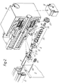
- a blind including a headrail 10 having depending therefrom, in a conventional way, a plurality of vertically extending slats or louvers 12.
- These slats or louvers are capable of being rotated about their central vertical axis to provide a tilting motion and are capable of being moved to and from a retracted position either to one side or both sides of the headrail.
- a mechanism 14 mounted in the end of the headrail 10 is a mechanism 14 according to the invention, this being operated by a first operating bead chain 16.
- the mechanism 14 is also capable of operating a second bead chain 18 formed from a plurality of elongate cylindrical plastic beads 20 for moving the slats to and from the retracted position.
- the total length of the beads of the second bead chain 18 together being greater than half the length of the whole bead chain thereby to increase the stiffness of the bead chain 18.
- a driving part 26 is adapted to be driven by the common actuating member 22 and itself cooperates, in a dog clutch type coupling to be described later, with a first driven element 27.
- a driving part 26 Located adjacent the driving part 26 are stacked the parts of the lost motion mechanism 24 in the form of several lost motion discs 28,29 to be described later.
- a second driven element 30 Associated with the last or left most of these discs 29 is a second driven element 30, the outer surface of which is in the form of a bead chain pulley adapted to engage a looped part of the second bead chain 18.
- a housing guiding piece 32 which serves as a guide for the second bead chain 18 within the housing.
- An end insert or housing base 34 closes the housing and these assembled parts can readily be seen in the upper part of Figure 2. It will be noted that there is additionally a coil compression spring 36 located between the common actuating member 22 and the driving part 26.
- the driving part 26 can be seen to include a hub 38 having associated with the left-end thereof dog clutch members 40 and at the right-end of the hub 38 is a peripheral flange 42 having on the left face an annular groove 44 interrupted by an axial abutment 46.
- the interior of the hub 38 is dimensioned to accept the spring 36 and the right-hand end part of the hub is provided with keyways 48 adapted to engage keys (not shown) on the actuating member 22 to cause rotation thereof while allowing relative axial movement.
- the first driven element 27 comprises further dog clutch members 50 releasibly engageable with the dog clutch members 40 associated with the hub 38 of the driving part 26 and the first driven element 27 is also provided with gear teeth 52 engageable with a gear wheel 54 which is used to drive a tilt rod 56.
- Gear wheel 54 and tilt rod 56 have been shown in the drawing entirely schematically and very much in a different position, they actually being located substantially adjacent the bead chain 18.
- the tilt rod is used to cooperate with a conventional mechanism for tilting, that is to say changing the angular position of the louvers or slats 12.
- the discs 28 of the lost motion device are circular and essentially flat and provided on opposite faces with projections 58, the projection on one face being slightly angularly offset in comparison to the projection 58 on the opposite face, as can be seen in Figures 3a, 3b and 3c.
- end disc 29 is also essentially flat and provided on one face with an abutment projection 58.
- ramp 60,62 replace the other projection 58 of the discs 28.
- the ramp 60,62 provide inclined faces and a positive stop 64 which is located centrally off of the upper parts of the ramps 60,62, but radially inwardly thereof to provide a compact structure of said end disc.
- the second driven element 30 includes a pulley portion 66 for the second bead chain 18, and facing the end disc 29 of the lost motion discs, ramps 68 and 70, a corresponding positive stop 72.
- the first bead chain 16 is pulled causing the actuating member 22 to rotate. This will cause, via the keyways 48 and the corresponding keys on the member 22, the driving part 26 to rotate.
- the dog clutch thereon through spring 36, will be engaged with the dog clutch portion of the first driven element 27 causing that to rotate which in turn will cause the gear wheel 54 and tilt drive shaft 56 to rotate thereby tilting the slats 12.
- the first or right-hand most disc 28 will eventually be caused to rotate by the axial abutment 46 of the driven part 26 engaging the projection 58 and as soon as its opposite projection engages with the corresponding projection 58 of the next disc, that disc will rotate by a similar amount and so on.
- a lost motion connection will thereby be given whereby approximately five or six turns of the driven member 26 are allowed to take place.
- the friction encountered by the second driven element 30 initially will keep this ele-ment stationary during the engagement of the ramps 60,62 of the last disc 28 with the ramps 68,70 of the second driven element 30. This friction is at least to a certain extent produced by the stiffness of the second bead chain 18.
- confronting faces of the discs 28 and second driven element 30 need not be identical as illustrated.
- one face could be provided with a cam, which rides on a ramp provided only on a single one of the confronting faces.
- the positive stop could be integrally formed with the ramp.
- this will reduce the axial volume of the lost motion mechanism, which is important to reduce the total volume so that an adequate number of discs 28,29 can be accommodated within as small a space as possible.
Landscapes
- Engineering & Computer Science (AREA)
- Structural Engineering (AREA)
- Architecture (AREA)
- Civil Engineering (AREA)
- Blinds (AREA)
- Operating, Guiding And Securing Of Roll- Type Closing Members (AREA)
- Mechanical Operated Clutches (AREA)
- Wing Frames And Configurations (AREA)
- Vehicle Body Suspensions (AREA)
- Jib Cranes (AREA)
Applications Claiming Priority (2)
| Application Number | Priority Date | Filing Date | Title |
|---|---|---|---|
| GB9015828 | 1990-07-18 | ||
| GB9015828A GB2246155A (en) | 1990-07-18 | 1990-07-18 | An operating mechanism for a blind or shielding device. |
Publications (3)
| Publication Number | Publication Date |
|---|---|
| EP0467627A2 true EP0467627A2 (fr) | 1992-01-22 |
| EP0467627A3 EP0467627A3 (en) | 1992-06-17 |
| EP0467627B1 EP0467627B1 (fr) | 1995-04-19 |
Family
ID=10679297
Family Applications (1)
| Application Number | Title | Priority Date | Filing Date |
|---|---|---|---|
| EP91306403A Expired - Lifetime EP0467627B1 (fr) | 1990-07-18 | 1991-07-15 | Mécanisme d'entraînement de stores ou dispositifs de blindage |
Country Status (8)
| Country | Link |
|---|---|
| US (1) | US5390721A (fr) |
| EP (1) | EP0467627B1 (fr) |
| AT (1) | ATE121494T1 (fr) |
| AU (1) | AU641527B2 (fr) |
| CA (1) | CA2047311C (fr) |
| DE (1) | DE69109003T2 (fr) |
| GB (1) | GB2246155A (fr) |
| IL (1) | IL98883A (fr) |
Cited By (1)
| Publication number | Priority date | Publication date | Assignee | Title |
|---|---|---|---|---|
| US6474393B1 (en) | 1999-07-14 | 2002-11-05 | Hunter Douglas Industries Bv | Drive mechanism and head rail for a blind |
Families Citing this family (12)
| Publication number | Priority date | Publication date | Assignee | Title |
|---|---|---|---|---|
| US5887693A (en) * | 1997-08-19 | 1999-03-30 | Hsu; Mu-Chuan | Adjusting device for controlling switch |
| US6648050B1 (en) | 1997-11-04 | 2003-11-18 | Andrew J. Toti | Spring drive system and window cover |
| US6536503B1 (en) * | 1999-03-23 | 2003-03-25 | Hunter Douglas Inc. | Modular transport system for coverings for architectural openings |
| US7193050B2 (en) * | 2000-02-18 | 2007-03-20 | Genentech, Inc. | Secreted and transmembrane polypeptides and nucleic acids encoding the same |
| EP1435426B1 (fr) * | 2002-12-30 | 2010-06-16 | Ober S.r.l. | Dispositif de renversement pour un store à lamelles |
| US20060207729A1 (en) * | 2005-03-17 | 2006-09-21 | Fu-Lai Yu | Control mechanism for a window covering |
| US7665502B2 (en) * | 2006-12-14 | 2010-02-23 | Hunter Douglas Industries Bv | Architectural covering |
| AT507816A1 (de) * | 2009-01-27 | 2010-08-15 | Franz Kraler | Antriebs- und wendevorrichtung für die lamellen einer jalousie |
| WO2012093092A1 (fr) | 2011-01-06 | 2012-07-12 | Hunter Douglas Industries B.V. | Mécanisme d'entraînement pour un arbre d'enroulement d'un revêtement architectural et revêtement architectural amélioré |
| CN103726776B (zh) * | 2013-08-22 | 2015-09-02 | 杭州欧卡索拉科技有限公司 | 时序控制滑块系统及应用该滑块系统的百叶窗升降翻转器 |
| AU2016204260B2 (en) | 2015-06-25 | 2021-04-08 | Hunter Douglas Inc. | Shutter assembly with motorized louver drive system |
| US10407977B2 (en) | 2016-12-28 | 2019-09-10 | Hunter Douglas Inc. | Motorized shutter assembly |
Family Cites Families (12)
| Publication number | Priority date | Publication date | Assignee | Title |
|---|---|---|---|---|
| US443769A (en) * | 1890-12-30 | Drive-chain | ||
| US1193008A (en) * | 1916-08-01 | Clutch | ||
| US1119572A (en) * | 1912-02-09 | 1914-12-01 | William F Butler | Flexible shafting. |
| US3455364A (en) * | 1967-06-17 | 1969-07-15 | Isamu Fukuoka | Device for driving vertical slat venetian blind |
| US3789905A (en) * | 1971-08-22 | 1974-02-05 | Nichi Bei Blind Kogyo Kk | Vertical type venetian blind |
| CH574559A5 (fr) * | 1972-08-08 | 1976-04-15 | Franciaflex | |
| CH585851A5 (fr) * | 1974-03-15 | 1977-03-15 | Gross Hans | |
| FR2331668A1 (fr) * | 1975-11-17 | 1977-06-10 | Carpano & Pons | Mecanisme d'entrainement et application a un store a lames verticales orientables |
| DE2554991C3 (de) * | 1975-12-06 | 1981-12-17 | Hügin, Walter, 7859 Efringen-Kirchen | Antriebsvorrichtung für Lamellenjalousien |
| US4224973A (en) * | 1977-12-05 | 1980-09-30 | Walter Hugin | Drive mechanism, particularly for moving and turning the slats of a blind |
| FI70978C (fi) * | 1981-12-07 | 1986-10-27 | Bratschi Silent Gliss | Lamellgardin |
| DE3306407A1 (de) * | 1983-02-24 | 1984-08-30 | Gross, Hans, Dipl.-Ing., 7000 Stuttgart | Antriebsvorrichtung fuer lamellenvorhaenge |
-
1990
- 1990-07-18 GB GB9015828A patent/GB2246155A/en not_active Withdrawn
-
1991
- 1991-07-15 EP EP91306403A patent/EP0467627B1/fr not_active Expired - Lifetime
- 1991-07-15 DE DE69109003T patent/DE69109003T2/de not_active Expired - Fee Related
- 1991-07-15 AT AT91306403T patent/ATE121494T1/de not_active IP Right Cessation
- 1991-07-17 CA CA002047311A patent/CA2047311C/fr not_active Expired - Fee Related
- 1991-07-18 IL IL9888391A patent/IL98883A/en not_active IP Right Cessation
- 1991-07-18 US US07/731,782 patent/US5390721A/en not_active Expired - Fee Related
- 1991-07-18 AU AU81149/91A patent/AU641527B2/en not_active Ceased
Cited By (2)
| Publication number | Priority date | Publication date | Assignee | Title |
|---|---|---|---|---|
| US6474393B1 (en) | 1999-07-14 | 2002-11-05 | Hunter Douglas Industries Bv | Drive mechanism and head rail for a blind |
| US6637492B2 (en) | 1999-07-14 | 2003-10-28 | Hunter Douglas Industries B.V. | Drive mechanism and head rail for a blind |
Also Published As
| Publication number | Publication date |
|---|---|
| EP0467627B1 (fr) | 1995-04-19 |
| CA2047311C (fr) | 1995-06-13 |
| DE69109003T2 (de) | 1995-08-31 |
| GB9015828D0 (en) | 1990-09-05 |
| US5390721A (en) | 1995-02-21 |
| AU641527B2 (en) | 1993-09-23 |
| ATE121494T1 (de) | 1995-05-15 |
| IL98883A (en) | 1993-05-30 |
| AU8114991A (en) | 1992-01-23 |
| GB2246155A (en) | 1992-01-22 |
| EP0467627A3 (en) | 1992-06-17 |
| CA2047311A1 (fr) | 1992-01-19 |
| DE69109003D1 (de) | 1995-05-24 |
| IL98883A0 (en) | 1992-07-15 |
Similar Documents
| Publication | Publication Date | Title |
|---|---|---|
| EP0467627B1 (fr) | Mécanisme d'entraînement de stores ou dispositifs de blindage | |
| JP4249818B2 (ja) | 外部バック・ミラー | |
| GB2049004A (en) | Louvered venetian blind with vertical louvers | |
| US5159854A (en) | Gear drive unit | |
| US6076592A (en) | Curtain operating assembly | |
| JP2009121232A (ja) | 建築物の開口部の覆いの昇降機構を制御するための制御ユニット | |
| CA1291415C (fr) | Organe d'embrayage pour mecanisme de manoeuvre a engrenage | |
| GB2049006A (en) | Louvered venetian blind with vertically arranged louveres | |
| US6651721B2 (en) | Method and apparatus for operating a blind | |
| US5266068A (en) | Vertical blind with single-element drive | |
| US4557159A (en) | Driving mechanism for slat curtains | |
| US4444243A (en) | Shutter for windows or the like | |
| US4986400A (en) | Bi-directional spring clutch for reducing worm gear drive | |
| CN109477345B (zh) | 门锁 | |
| US5605072A (en) | Load-isolated, single-cycle mechanism | |
| US20220145698A1 (en) | Folding/unfolding device for a window shade | |
| JP2001165539A5 (fr) | ||
| JP7671211B2 (ja) | 操作装置 | |
| JP3478599B2 (ja) | シートフィーダ機構 | |
| AU784289B2 (en) | A method and apparatus for operating a blind | |
| JPH035669Y2 (fr) | ||
| JP2007285326A (ja) | 2ウェイクラッチユニット | |
| JP3010854B2 (ja) | スタータ | |
| JPH0358034B2 (fr) | ||
| JPH06260049A (ja) | スイッチ機構の基準位置設定装置および基準位置設定方法 |
Legal Events
| Date | Code | Title | Description |
|---|---|---|---|
| PUAI | Public reference made under article 153(3) epc to a published international application that has entered the european phase |
Free format text: ORIGINAL CODE: 0009012 |
|
| AK | Designated contracting states |
Kind code of ref document: A2 Designated state(s): AT BE CH DE DK ES FR GB GR IT LI NL SE |
|
| PUAL | Search report despatched |
Free format text: ORIGINAL CODE: 0009013 |
|
| AK | Designated contracting states |
Kind code of ref document: A3 Designated state(s): AT BE CH DE DK ES FR GB GR IT LI NL SE |
|
| 17P | Request for examination filed |
Effective date: 19920717 |
|
| 17Q | First examination report despatched |
Effective date: 19940111 |
|
| GRAA | (expected) grant |
Free format text: ORIGINAL CODE: 0009210 |
|
| AK | Designated contracting states |
Kind code of ref document: B1 Designated state(s): AT BE CH DE DK ES FR GB GR IT LI NL SE |
|
| PG25 | Lapsed in a contracting state [announced via postgrant information from national office to epo] |
Ref country code: IT Free format text: LAPSE BECAUSE OF FAILURE TO SUBMIT A TRANSLATION OF THE DESCRIPTION OR TO PAY THE FEE WITHIN THE PRESCRIBED TIME-LIMIT;WARNING: LAPSES OF ITALIAN PATENTS WITH EFFECTIVE DATE BEFORE 2007 MAY HAVE OCCURRED AT ANY TIME BEFORE 2007. THE CORRECT EFFECTIVE DATE MAY BE DIFFERENT FROM THE ONE RECORDED. Effective date: 19950419 Ref country code: AT Effective date: 19950419 Ref country code: GR Free format text: LAPSE BECAUSE OF FAILURE TO SUBMIT A TRANSLATION OF THE DESCRIPTION OR TO PAY THE FEE WITHIN THE PRESCRIBED TIME-LIMIT Effective date: 19950419 Ref country code: ES Free format text: THE PATENT HAS BEEN ANNULLED BY A DECISION OF A NATIONAL AUTHORITY Effective date: 19950419 Ref country code: CH Effective date: 19950419 Ref country code: DK Effective date: 19950419 Ref country code: LI Effective date: 19950419 |
|
| REF | Corresponds to: |
Ref document number: 121494 Country of ref document: AT Date of ref document: 19950515 Kind code of ref document: T |
|
| ET | Fr: translation filed | ||
| REF | Corresponds to: |
Ref document number: 69109003 Country of ref document: DE Date of ref document: 19950524 |
|
| PG25 | Lapsed in a contracting state [announced via postgrant information from national office to epo] |
Ref country code: SE Effective date: 19950719 |
|
| REG | Reference to a national code |
Ref country code: CH Ref legal event code: PL |
|
| PGFP | Annual fee paid to national office [announced via postgrant information from national office to epo] |
Ref country code: BE Payment date: 19950911 Year of fee payment: 5 |
|
| PLBE | No opposition filed within time limit |
Free format text: ORIGINAL CODE: 0009261 |
|
| STAA | Information on the status of an ep patent application or granted ep patent |
Free format text: STATUS: NO OPPOSITION FILED WITHIN TIME LIMIT |
|
| 26N | No opposition filed | ||
| PGFP | Annual fee paid to national office [announced via postgrant information from national office to epo] |
Ref country code: NL Payment date: 19960716 Year of fee payment: 6 |
|
| PG25 | Lapsed in a contracting state [announced via postgrant information from national office to epo] |
Ref country code: BE Effective date: 19960731 |
|
| BERE | Be: lapsed |
Owner name: HUNTER DOUGLAS INDUSTRIES B.V. Effective date: 19960731 |
|
| PG25 | Lapsed in a contracting state [announced via postgrant information from national office to epo] |
Ref country code: NL Free format text: LAPSE BECAUSE OF NON-PAYMENT OF DUE FEES Effective date: 19980201 |
|
| NLV4 | Nl: lapsed or anulled due to non-payment of the annual fee |
Effective date: 19980201 |
|
| PGFP | Annual fee paid to national office [announced via postgrant information from national office to epo] |
Ref country code: GB Payment date: 20000713 Year of fee payment: 10 |
|
| PG25 | Lapsed in a contracting state [announced via postgrant information from national office to epo] |
Ref country code: GB Free format text: LAPSE BECAUSE OF NON-PAYMENT OF DUE FEES Effective date: 20010715 |
|
| GBPC | Gb: european patent ceased through non-payment of renewal fee |
Effective date: 20010715 |
|
| PGFP | Annual fee paid to national office [announced via postgrant information from national office to epo] |
Ref country code: FR Payment date: 20040708 Year of fee payment: 14 |
|
| PGFP | Annual fee paid to national office [announced via postgrant information from national office to epo] |
Ref country code: DE Payment date: 20040722 Year of fee payment: 14 |
|
| PG25 | Lapsed in a contracting state [announced via postgrant information from national office to epo] |
Ref country code: DE Free format text: LAPSE BECAUSE OF NON-PAYMENT OF DUE FEES Effective date: 20060201 |
|
| PG25 | Lapsed in a contracting state [announced via postgrant information from national office to epo] |
Ref country code: FR Free format text: LAPSE BECAUSE OF NON-PAYMENT OF DUE FEES Effective date: 20060331 |
|
| REG | Reference to a national code |
Ref country code: FR Ref legal event code: ST Effective date: 20060331 |