EP0467629A2 - Schleifenkompilierverfahren und -gerät für ein Datenverarbeitungssystem - Google Patents
Schleifenkompilierverfahren und -gerät für ein Datenverarbeitungssystem Download PDFInfo
- Publication number
- EP0467629A2 EP0467629A2 EP91306414A EP91306414A EP0467629A2 EP 0467629 A2 EP0467629 A2 EP 0467629A2 EP 91306414 A EP91306414 A EP 91306414A EP 91306414 A EP91306414 A EP 91306414A EP 0467629 A2 EP0467629 A2 EP 0467629A2
- Authority
- EP
- European Patent Office
- Prior art keywords
- instructions
- loop
- instruction
- executed
- processing system
- Prior art date
- Legal status (The legal status is an assumption and is not a legal conclusion. Google has not performed a legal analysis and makes no representation as to the accuracy of the status listed.)
- Granted
Links
Images




Classifications
-
- G—PHYSICS
- G06—COMPUTING OR CALCULATING; COUNTING
- G06F—ELECTRIC DIGITAL DATA PROCESSING
- G06F8/00—Arrangements for software engineering
- G06F8/40—Transformation of program code
- G06F8/41—Compilation
- G06F8/45—Exploiting coarse grain parallelism in compilation, i.e. parallelism between groups of instructions
- G06F8/451—Code distribution
- G06F8/452—Loops
-
- G—PHYSICS
- G06—COMPUTING OR CALCULATING; COUNTING
- G06F—ELECTRIC DIGITAL DATA PROCESSING
- G06F8/00—Arrangements for software engineering
- G06F8/40—Transformation of program code
- G06F8/41—Compilation
- G06F8/45—Exploiting coarse grain parallelism in compilation, i.e. parallelism between groups of instructions
Definitions
- the present invention relates to a method and apparatus for compiling loops of instructions of computer programs and for executing the compiled loops in a data processing system.
- a compiler of a data processing system typically converts source code of computer programs to object code.
- Source code is easily understandable by computer programmers and is generally written in a high level computer programming language, e.g., C, PASCAL, or BASIC.
- Object code is represented by strings of binary numbers, e.g., 0101 or 1010, and is capable of being understood by the data processing system which executes the computer programs.
- assembly language is also considered the closest programming language to object code and is understandable by computer programmers.
- One line of source code of a computer program instructs the data processing system to perform one or more operation(s) or function(s), e.g., read data from memory and store the read data in variable VAR.
- An ordered set of one or more lines of source code (or object code) may be referred to as a loop of instructions. Loops are used to execute repeatedly a set of one or more instructions by a data processing system until a particular condition(s) is/are true. Typically, the condition appears in the line of source code which signifies the beginning or the end of the loop.
- the instructions included in a loop are executed n-times (or n iterations) until a predetermined condition is satisfied. For example, in an iterative loop, a loop of instructions will be executed a specified number of times, e.g. 100 times. During the n-times iteration of an iterative loop, e.g., the second iteration, if the condition is not satisfied (e.g., the loop has not been executed 100 times), then the next iteration, or the (n+1)-times iteration of the loop, e.g., the third iteration, is executed.
- loops e.g., do-while loops
- execute the set of instructions until a condition e.g., X is not equal to 1.
- the data processing system also checks to determine whether the condition to escape (or end) the execution of the loop is satisfied after each iteration.
- one microprocessor executes the n-times iteration of a loop and, before completing the n-times iteration, a second microprocessor begins executing the next iteration, or (n+1)-times iteration, of the loop.
- instructions from different iterations (n-times and (n+1)-times) of a loop can be executed at the same time using data processing systems including a plurality of microprocessors.
- one or more instructions of an iteration of a loop may not be executed according to the order for the complete loop execution set up by the computer programmer. Accordingly, if the intended order of execution is disturbed, and the loop contains multiple instructions which refer to and alter the same variable (or register or the same memory address), the result of executing the loop will differ from the originally intended result.
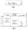
- the data processing system will execute the successive instruction(s) a total of 100 times.
- this instruction sets the value of one entry (or element) in an array to the value of another entry in the array plus the value of the variable B.
- "A" represents the name of an array.
- An array is a collection of data that is given one name, in this case "A”.
- Each element can be identified by a number, commonly referred to as a subscript, which indicates the row, and in some cases column, in which the element is located.
- the first element in the array A is referred to by "A[O]” and the second "A[1]” and so forth.
- variables "i" which is incremented during execution of the loop are also included in the instruction (2) of Figure 1.
- Variables "p” and “q” and “B” may be initialized or set to be equal to specific numbers prior to the execution of the loop of Figure 1. Changing the value of i with each iteration of the loop, as discussed above, necessarily affects the results of the execution of each iteration because the value of i impacts which element of the array A will be set equal to which other element of array A plus the value of B.
- Figure 2 illustrates an example of the parallel execution of multiple iterations of the loop of instructions illustrated in Fig. 1.
- instruction (2) of Figure 1 is separated into 3 steps, for example: load A[q+1], add B, and store A[p+1). These three steps assume the existence of a single register, for example, R1, in which to manipulate (load and add) the values of elements in the array A, and the steps are similar to the assembly language level instructions corresponding to instruction (2) of Figure 1.
- the first step “load A[q+1]” is equivalent to "load the contents of element A[q+1] into the register R1
- the second step “add B” is the same as “add the value of variable B to the contents of register R1
- the third step “store A[p+1]” is the same as "store the contents of register R1 in element A[p+1] of array A.”
- the set of instructions for each iteration of the loop e.g., iteration (i-times), iteration ((i+1)-times), and iteration (((i+1)+1)-times)
- the left column of Figure 2 represents time periods.
- the compiler of the data processing system has generally been used to make this determination while compiling the source code into object code. Using conventional methods, the compiler decides which steps of a loop can be parallely executed by attempting to identify steps of the loop which refer to the same register or variable. If the execution order of the instructions of a loop is to be changed to accommodate parallel processing, the compiler of the data processing system generally generates object code instructions indicating which steps can be parallely executed. If the execution order of the instructions of the loop cannot be changed, the compiler generates loop instructions indicating which steps cannot be parallely executed.
- the present invention has been made in view of the above circumstances and has an object to provide a compiler method and apparatus in a data processing system, which allows for a loop of instructions to be parallely executed if it is determined that the loop of instructions is able to be parallely executed at execution time.
- the present invention is comprised of a loop compiler in a data processing system which includes a plurality of processors, each capable of executing object programs.
- the loop compiler compiles an object program consisting of a plurality of instructions to be executed by the data processing system.
- a loop consist of a plurality of instructions to be executed a plurality of iterations by a one of the plurality of processors.
- the loop compiler comprises a loop instructions extraction means for extracting a loop from the plurality of instructions; a resource reference extraction means for extracting resources read by at least one of the instructions in the extracted loop; a resource change extraction means for extracting resources changed by at least one of the instructions in the extracted loop; a loop parallel decision means for determining, in accordance with the extracted resources extracted by the resource reference extraction means and the resource change extraction means, whether a first iteration and a second iteration of the loop can be parallely executed; and a code generation means for generating, in accordance with the determination of the loop parallel decision means, object instructions, including a plurality of types of object instructions for the object program including a first type wherein the object instructions are parallely executed by the plurality of processors, a second type wherein the object instructions are executed by a one of the plurality of processors, and a third type wherein the object instructions include branch parallel execution instructions, non-parallel execution instructions and parallel execution instructions, wherein the branch parallel execution instructions are used, during execution of the object program, to
- This invention is preferably implemented by a microcomputer or other data processing system. Such a data processing system may be conventional.
- a data processing system may be conventional.
- the preferred implementation is disclosed hereinafter in functional schematic form. To understand the present invention, and in view of the fact that object code is difficult to read and understand, all object code will be illustrated using corresponding assembly language level pseudo code.
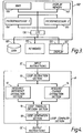
- the computer system or platform 100 is comprised of a central processing unit (or CPU) 102, a disk drive 105, a keyboard 115, and a display 120.
- the platform 100 may also optionally include other external devices (not shown), such as a videodisc system or an electronic instrument system.
- the CPU 102 is comprised of an input/output unit 130, a random access memory unit (or RAM) 135, a display memory unit 140, and two microprocessors 150 and 155, respectively. These units are all well known and operate under control of the system software to process various inputs and provide the outputs necessary to generate desired textual and graphic display information on the display screen 122 of the display 120 or other output unit (not shown).
- Display memory 140 is a specialized section of RAM which is used to store bit patterns (pixel data) which are read out in an appropriate synchronization with the display beam of the display 120 in order to provide the desired display graphics and text.
- the disk drive 105 is also conventional and is provided to permit the ready interchange of control and application software and to provide a source of mass storage for the computer system.
- the keyboard 115 of the computer system 100 of the preferred implementation of the present invention acts as a means of inputting textual or alphanumeric information into the CPU 102.
- the display 120 is comprised of a display screen 122 for displaying the graphic and alphanumeric information output from the CPU 102.
- the system 100 also includes a compiler which may be a part of the RAM 135 or stored in the Disk 105.
- the compiler generally interprets or translates input source code computer programs (written, for example, in the FORTRAN programming language) into object code. These conversion processes are generally conventional and will not be explained. However, the operations of the preferred implementation which compiles loops of instructions, and forms a part of the compiler, will be explained.
- FIG. 4 illustrates a block diagram of the preferred implementation of the present invention.
- the loop compiler section 8 forms a part of the compiler which may be a part of the RAM 135 or stored in the Disk 105.
- the loop compiler section 8 is the section of a compiler which processes loops of instructions in object code to determine whether iterations of the loops can be parallely executed by multiple processors.
- the loop compiler section 8 includes a loop extraction section 10, a resource reference extraction section 12, a resource change extraction section 14, a loop parallel decision section 16, and a code generation section 18.
- the loop extraction section 10 extracts loops from input instructions IC which were previously converted from source code to object code by a different section of the compiler.
- the resource reference extraction section 12 then identifies any resources referenced (or read) in each of the instructions of the loop from IC and generates a table listing these resources. Resources include registers, memory addresses, data stored in registers, or data stored in memory addresses.
- the resource change extraction section 14 identifies resources changed (or written) in the loop from IC and generates a table of these resources.
- the loop parallel decision section 16 determines whether the n-times iteration and the (n+1)-times iteration of the loop from IC can be parallely executed, according to the tables generated by the resource reference extraction section 12 and the resource change extraction section 14, respectively.
- the code generation section 18 generates the appropriate object code instructions to be output, OC.
- the OC may be parallel execution instructions or non-parallel execution instructions, or both, according to decision result of the loop parallel decision section 16.
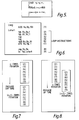
- Figure 5 is an example of source code for a loop of instructions written in a high level computer programming language.
- the source code (loop) shown in Figure 5 will be used to explain the operations of the loop compiler section 8 of Figure 4.
- the loop of instructions in Figure 5 generally instructs the system 100 to read the 1-byte data corresponding to (or stored in) the memory address associated with variables q and r from memory and to write the sum of these data in the memory address associated with variable p.
- Figure 6 illustrates the assembly language level pseudo code corresponding to the object code generated by a compiler for the source code of Figure 5.
- assembly language level code since assembly language level code can be easily understood, the operations of the present invention will be described using assembly language examples rather than the more difficult object code.
- the assembly language code of Figure 6 it is assumed that the memory address corresponding to variables "p, q, r" are already loaded into registers "Rp, Rq, Rr,” respectively.
- "Lseg:” and “Lstart” of Figure 6 are called labels and are used to identify a line in the assembly language code.
- Figure 7 illustrates the sequential execution of instructions (2)-(9) of Figure 6. If the loop of instructions represented by instructions (2)-(9) are executed sequentially, then (n+1)-times iteration of the loop is executed after the n-times iteration is completed as illustrated in Figure 7.
- both microprocessors 150 and 155 of Figure 3 are operating and, each microprocessor processes a different iteration of the loop, instructions (2)-(9).
- instruction (6) in the n-times iteration of the loop is executed by microprocessor 1 150, while instruction (2) of the (n+1)-times iteration is executed simultaneously by microprocessor 2 155 of Figure 3.
- instruction (7) of the n-times iteration of the loop is executed by microprocessor 1 150, while instruction (3) of the (n+1)-times iteration of is executed simultaneously by microprocessor 2 155 of Figure 3.
- Figure 8 also illustrates this same simultaneous sequential execution of instruction (8) of the n-times iteration and instruction (4) of the (n+1)-times iteration, and instruction (9) of the n-times iteration and instruction (5) of the (n+1)-times iteration. Therefore, the instructions (2)-(9) are not executed according to the originally programmed order. For example, instruction (2) of the (n+1)-times iteration is executed before instruction (7) of the n-times iteration.
- the resource reference extraction section 12 and the resource change extraction section 14 of the preferred implementation are used to help determine whether a change in the order of executing the loop will effect the results of the loop.
- the sections 12 and 14 help determine whether executing instruction (2) of the (n+1)-times iteration before instruction (7) of the n-times iteration will effect the results.
- FIG. 9 is a flow diagram 900 of the processing steps of the resource reference extraction section 12 of the preferred implementation.
- the section 12 extracts (or identifies) instructions which refer to (or read) data from memory (step 81).
- instructions (2) and (3) are extracted because "ldb" or load is the type of instruction which reads data from memory.
- Section 12 then records the instruction number and memory address referenced by the instruction in a resource reference extraction list (step 83).
- the memory address for q in register Rq and the memory address for r in register Rr are referenced. Therefore, q+n and r+n are added to the resource reference extraction list; where q and r are memory addresses and n is merely the loop iteration number.
- Figure 10 illustrates an example of a resource reference extraction list 90 generated by the resource reference extraction section 12.
- the example list 90 therefore includes instructions (2) and (3), and the corresponding resource referenced by each of these instructions, q+n and r+n, respectively.
- the section 12 extracts instructions which reference data in registers (step 85).
- instructions (6), (7), and (8) are extracted because "add", "Stb" and "Cmp" are instructions which reference data in registers.
- the section 12 then records the instruction number and register name referenced by each of the instructions which reference data in registers in the resource reference extraction list (step 87). For example, using the assembly language listing in Figure 6, Rs and Rt of instruction (6), Ru of instruction (7) and Rp of instruction (8) are added to the resource reference extraction list illustrated in Figure 10.
- the resource reference extraction section 12 operates simultaneously with the resource change extraction section 14.
- Figure 11 is a flow diagram 1100 of the steps performed by the resource change extraction section 14.
- the section 14 first extracts instructions which change data stored in memory (step 101). Using Figure 6, for example, instruction (7) is extracted because "Stb" is an instruction which alters data stored in memory.
- the section 14 then records the instruction number and memory address, which corresponding data is changed by the extracted instruction, in a resource change extraction list (step 103). For example, in Figure 6, data corresponding to memory address p in register Rp is changed. Therefore, p+n is added to the resource changed extraction list. The p symbolizes the memory address of the data to be changed and the n is for the iteration of the loop.
- Figure 12 is an example of a resource change extraction list 110 generated by the section 14 for the code of Figure 6. Instruction (7) and the corresponding p+n are in the list 110.
- the section 14 then identifies and extracts from the loop of instructions, those instructions that change data stored in registers (step 105). Using Figure 6, for example, instructions (2), (3) and (6) are extracted. The section 14 then records the instruction number and register name changed by the instruction in the resource change extraction list (step 107). Using Figure 6, for example, Rs of instruction (2), Rt of instruction (3), and Ru of instruction (6) are added to the resource change extraction list of Figure 12.
- the section 16 generally determines whether different iterations of the input loop can be executed parallely using multiple microprocessors of the type included in the system 100 and determines which stage or instruction parallel execution can begin using the lists generated by the resource reference extraction section 12 and the resource change extraction section 14.
- FIGS. 13A-13C illustrate a flow diagram 1300 of the operations of the loop parallel decision section 16 of the loop compiler section 8 ( Figure 4).
- the section 16 first examines or identifies the register used by the first instruction of the loop (step 132), and then locates the next instruction (referred to as the "other instruction") in the loop that uses that same register (step 134). Next, the section 16 creates an instruction order change table indicating that the other instruction of the n-times iteration of the loop is executed simultaneously with the first instruction of the (n+1)-times iteration of the loop.
- the loop parallel decision section 16 uses the loop of Figure 6, the loop parallel decision section 16 generates, in step 136, a table of the type illustrated in Figure 14.
- the change order table 200 of Figure 14 the columns correspond to the n-times iteration of the loop of Figure 6 and the rows correspond to the (n+1)-times iteration of the loop of Figure 6.
- the reverse order change where, for example, the correct instruction order is: instruction (a) followed by instruction (b) or (a)-(b), and the reverse order or (b)-(a) is executed.
- the second type of order change is where instruction (a) and (b) are executed at the same time rather than sequentially.
- the triangle " ⁇ W" is used to indicate that the instructions are executed simultaneously and the circles "O" are used to indicate that the instructions are executed out of order.
- the triangle in the column corresponding to instruction (6) in the n-times iteration of the loop of Figure 6 and the row corresponding to instruction (2) of the (n+1)-times iteration of the loop of Figure 6 generated by the loop decision parallel section 16 indicates that these instructions (instruction (6) of the n-times iteration and instruction (2) of the (n+1)-times iteration) are executed simultaneously.
- the section 16 also indicates that instruction (7) of the n-times iteration is executed at the same times as instruction (3) of the (n+1)-times iteration; instruction (8) of the n-times iteration is executed at the same times as instruction (4) of the (n+1)-times iteration; and instruction (9) of the n-times iteration is executed at the same times as instruction (5) of the (n+1)-times iteration.
- the section 16 also indicates in the table 200, using circles, that instruction 2 of the (n+1)-times iteration is executed before instructions (7), (8) and (9) of the n-times iteration; instruction (3) of the (n+1)-times iteration is executed before instructions (8) and (9) of the n-times iteration; and instruction (4) of the (n+1)-times iteration is executed before instruction (9) of the n-times iteration.
- the loop parallel decision section 16 examines the entries in the change order table to determine whether one of these problem would occur if the order of instructions is changed.
- the loop parallel decision section 16 decides whether one of the change order problems would occur with respect to a set of two instructions corresponding to "O" in the change order table, and whether one of second and third change order problems would occur with respect to a set of two instructions corresponding to a triangle in the change order table.
- the section 16 next extracts the instruction numbers for two instructions corresponding to an entry in the change order table which indicates that the two instructions can be executed at the same time (step 138). For example, using table 200 of Figure 14, the section 16 would extract instruction (2) of the (n+1)-times iteration and instruction (6) of the n-times iteration.
- the section 16 then checks the n-times instruction number extracted from the change order table to determine whether that instruction number appears in the resource change extraction list (step 140). If yes, the section 16 extracts the change resource corresponding to the n-times instruction number from the resource change extraction list (step 142). Then, the section 16 determines whether the (n+1)-times instruction number of the instructions extracted from the change order table is written in the resource change extraction list or the resource reference extraction list (step 144).
- step 146 the section 16 extracts resource corresponding to the (n+1)-times instruction number from the list. The section 16 then determines whether the resource corresponding to the (n+1)-times instruction number is the same as the resource corresponding to the n-times instruction number (step 148). If yes, then the section 16 creates a condition equation indicating this result (step 150). The condition equation will be discussed below with reference to Figure 15.
- step 148 or if the n-times instruction number of the instruction numbers extracted from the change order table is not in the resource change extraction list (step 140 of Figure 13A), or if the (n+1)-times instruction number is not in either of the resource change extraction list or the resource reference extraction list (step 144 of Figure 13A), or after having created the condition equation (step 150), the section 16 determines whether there are any more entries in the change order table indicating the two instructions can be executed at the same time (step 152). If yes, then the flow of operation for the section 16 returns to step 138 of Figure 13A.
- step 152 there are no more entries in the change order table indicating that two instructions can be executed at the same time (step 152), and the section 16 extracts from the change order table, the first set of instructions (for the n-times iteration and the (n+1)-times iteration) indicating that the instruction, if simultaneously executed by multiple processors, would be in reverse order (step 154).
- the loop parallel decision section 16 then examines the extracted instruction numbers to determine whether the n-times instruction number is in either the resource reference extraction list or the resource change extraction list (step 156). If yes, then the section extracts the name of the resource corresponding to the n-times instruction from the list in which the instruction number was found (step 158).
- the flow of operation of the section 16 then continues on Figure 13C.
- the loop parallel decision section 16 next determines whether the (n+1)-times instruction of the instructions extracted from the change order table is in either of the resource reference extraction list or the resource change extraction list (step 160). If yes, then the section 16 extracts the name of the resource corresponding to the (n+1)-times instruction from the list in which the instruction number was found (step 162).
- the section 16 decides whether the resource corresponding to the n-times instruction and the resource corresponding to the (n+1)-times instruction are the same (step 164). If yes, then the section 16 creates a condition equation using these resources (step 166).
- step 164 or if the n-times instruction number of the instructions extracted from the change order table is not in either of the resource reference extraction list or the resource change extraction list (step 156), or if the (n+1)-times instruction number of the instructions extracted from the change order table is not in either of the resource reference extraction list or the resource change extraction list (step 160), then the section 16 determines whether there are any other sets of instructions in the change order table wherein the table indicates that these instruction may be executed out of the original order (step 168). If yes, then the flow of operation of the loop parallel decision section returns to step 154 of Figure 13B.
- the loop parallel decision section 16 creates a list of the sets of instructions which create problems or where the use of the same resources may create execution problems. This list consists of the condition equations discussed above.
- Figure 15 is an example of a list of condition equations created by the section 16 for the table 200 of Figure 14.
- the section 16 begins evaluation of the condition equations generated by steps 150 and 166. In evaluating the condition equations, the section 16 first determines whether the values for the resources in the condition equation are already determined (step 170). That is, whether the values for the resources can be predetermined during the compiling of the loop. If yes, then the condition equation is calculated using the predetermined values for the resources (step 172). If no condition equation can be evaluated (step 174), then the section 16 outputs "possible”. If at least one condition equation can be evaluated (step 174), then the section 16 outputs "impossible.”
- the section 16 outputs "unkownn" (step 178).
- the loop parallel decision section 16 can decide whether the above equations (3) and (4) can be evaluated. If at least one of these equations can be evaluated, the loop parallel decision section 16 outputs "impossible” to the code generation section 18. If both equations (3) and (4) cannot be evaluated, the loop parallel decision section 16 outputs "possible” to the code generation section 18. However, if initial value of "p", “q” and “r” are not predetermined, the loop parallel decision section 16 cannot decide whether the above equations (3) and (4) can be evaluated. Therefore, the loop parallel decision section 16 supplies "unknown" to the code generation section 18.
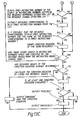
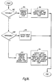
- Figure 16 illustrates a flow diagram 1600 of the code generation section 18 of the preferred implementation.
- the loop parallel decision section 16 outputs "possible,” “impossible,” or “unknown.” If the code generation section 18 receives "possible” from the section 16 (step 302), the code generation section 18 generates a partial overlap object code corresponding to the instructions of the loop that may be parallely executed (step 304) and outputs the input object code and the partial overlap code as the output code OC of Figure 4 (step 306).
- the code generation section 18 When the code generation section 18 receives "impossible" from the loop parallel decision section 16 (step 308), the code generation section 18 outputs as OC of Figure 4 the input object code which is sequentially executed.
- the OC in this case is the same object code input to the loop compiler section 8, and is the object code corresponding to the assembly language code illustrated in Figure 6 (step 310).
- the code generation section 18 receives "unknown" from the loop parallel decision section 16 indicating that no definitive decision can be made during compile time as to whether the loop can be parallely executed (step 308), the code generation section 18 generates object instructions which branches to a parallel execution instruction set or to a non-parallel execution instruction set, according to the condition at execution mode.
- the section 18 also generates the partial overlap code discussed above for the input object code (step 312) and outputs object code including: (1) the branching code; (2) the input object code for the loop to be used during execution if the iterations of loop are to be executed sequentially by a single processor; and (3) the input object code and partial overlap code to be used during execution if the iterations of the loop are to be parallely executed (step 314).
Landscapes
- Engineering & Computer Science (AREA)
- General Engineering & Computer Science (AREA)
- Theoretical Computer Science (AREA)
- Software Systems (AREA)
- Physics & Mathematics (AREA)
- General Physics & Mathematics (AREA)
- Devices For Executing Special Programs (AREA)
- Advance Control (AREA)
- Executing Machine-Instructions (AREA)
Applications Claiming Priority (2)
| Application Number | Priority Date | Filing Date | Title |
|---|---|---|---|
| JP2188138A JPH0475139A (ja) | 1990-07-18 | 1990-07-18 | ループ並列化装置 |
| JP188138/90 | 1990-07-18 |
Publications (3)
| Publication Number | Publication Date |
|---|---|
| EP0467629A2 true EP0467629A2 (de) | 1992-01-22 |
| EP0467629A3 EP0467629A3 (en) | 1992-10-28 |
| EP0467629B1 EP0467629B1 (de) | 1996-09-11 |
Family
ID=16218408
Family Applications (1)
| Application Number | Title | Priority Date | Filing Date |
|---|---|---|---|
| EP91306414A Expired - Lifetime EP0467629B1 (de) | 1990-07-18 | 1991-07-16 | Schleifenkompilierverfahren und -gerät für ein Datenverarbeitungssystem |
Country Status (4)
| Country | Link |
|---|---|
| US (1) | US5317743A (de) |
| EP (1) | EP0467629B1 (de) |
| JP (1) | JPH0475139A (de) |
| DE (1) | DE69121993D1 (de) |
Cited By (2)
| Publication number | Priority date | Publication date | Assignee | Title |
|---|---|---|---|---|
| WO1995031779A1 (en) * | 1994-05-16 | 1995-11-23 | British Telecommunications Public Limited Company | Instruction creation device |
| EP1461719A4 (de) * | 2001-12-04 | 2007-11-07 | Powerllel Corp | Paralleldatenverarbeitungssystem, verfahren und architektur |
Families Citing this family (33)
| Publication number | Priority date | Publication date | Assignee | Title |
|---|---|---|---|---|
| US5539911A (en) * | 1991-07-08 | 1996-07-23 | Seiko Epson Corporation | High-performance, superscalar-based computer system with out-of-order instruction execution |
| JP2921190B2 (ja) * | 1991-07-25 | 1999-07-19 | 日本電気株式会社 | 並列実行方式 |
| US5450554A (en) * | 1991-11-11 | 1995-09-12 | Matsushita Electric Industrial Co., Ltd. | Apparatus for detecting possibility of parallel processing and method thereof and a program translation apparatus utilized therein |
| JP2943464B2 (ja) * | 1991-12-09 | 1999-08-30 | 松下電器産業株式会社 | プログラム制御方法及びプログラム制御装置 |
| JPH08507889A (ja) * | 1993-03-15 | 1996-08-20 | シーメンス アクチエンゲゼルシヤフト | スーパースカラマイクロプロセッサ用のプログラムから並行的に処理可能な命令グループを機械的に生成する方法 |
| JPH0744508A (ja) * | 1993-08-03 | 1995-02-14 | Hitachi Ltd | プログラム分割方法 |
| JPH07110800A (ja) * | 1993-10-13 | 1995-04-25 | Matsushita Electric Ind Co Ltd | 最適化並列コンパイル装置及び最適化並列コンパイル方法 |
| JPH07319710A (ja) * | 1994-05-20 | 1995-12-08 | Matsushita Electric Ind Co Ltd | コンパイル処理方法 |
| JP2669603B2 (ja) * | 1994-12-15 | 1997-10-29 | インターナショナル・ビジネス・マシーンズ・コーポレイション | コンパイラにおけるコード生成方法及びコンパイラ |
| US5920724A (en) * | 1996-03-28 | 1999-07-06 | Intel Corporation | Software pipelining a hyperblock loop |
| US5854933A (en) * | 1996-08-20 | 1998-12-29 | Intel Corporation | Method for optimizing a computer program by moving certain load and store instructions out of a loop |
| US6339840B1 (en) * | 1997-06-02 | 2002-01-15 | Iowa State University Research Foundation, Inc. | Apparatus and method for parallelizing legacy computer code |
| US6085315A (en) * | 1997-09-12 | 2000-07-04 | Siemens Aktiengesellschaft | Data processing device with loop pipeline |
| US6272676B1 (en) * | 1998-01-13 | 2001-08-07 | Intel Corporation | Method and apparatus for finding loop— lever parallelism in a pointer based application |
| JP4190610B2 (ja) * | 1998-02-18 | 2008-12-03 | 富士通株式会社 | ロードモジュールの試験ルート決定装置 |
| JP3595158B2 (ja) * | 1998-03-13 | 2004-12-02 | 株式会社東芝 | 命令割り当て方法及び命令割り当て装置 |
| US6321312B1 (en) | 1998-07-01 | 2001-11-20 | International Business Machines Corporation | System and method for controlling peripheral device memory access in a data processing system |
| EP1062577A2 (de) * | 1998-12-08 | 2000-12-27 | Koninklijke Philips Electronics N.V. | Interpretiererprogrammausführungsverfahren |
| US6269440B1 (en) * | 1999-02-05 | 2001-07-31 | Agere Systems Guardian Corp. | Accelerating vector processing using plural sequencers to process multiple loop iterations simultaneously |
| US7146360B2 (en) | 2002-12-18 | 2006-12-05 | International Business Machines Corporation | Method and system for improving response time for database query execution |
| US7111287B2 (en) * | 2003-01-10 | 2006-09-19 | International Business Machines Corporation | Global processor resource assignment in an assembler |
| JP2008523523A (ja) * | 2004-12-13 | 2008-07-03 | コーニンクレッカ フィリップス エレクトロニクス エヌ ヴィ | プログラム内のループ用のコンパイル方法、コンパイル装置およびコンピュータシステム |
| JP4819442B2 (ja) * | 2005-09-01 | 2011-11-24 | 富士通株式会社 | コンパイル処理方法、コンパイル処理装置及びコンパイル処理プログラム |
| US8443351B2 (en) * | 2006-02-23 | 2013-05-14 | Microsoft Corporation | Parallel loops in a workflow |
| US8024714B2 (en) * | 2006-11-17 | 2011-09-20 | Microsoft Corporation | Parallelizing sequential frameworks using transactions |
| CN102483701A (zh) * | 2010-07-05 | 2012-05-30 | 松下电器产业株式会社 | 程序生成装置、程序生产方法及程序 |
| US10089277B2 (en) | 2011-06-24 | 2018-10-02 | Robert Keith Mykland | Configurable circuit array |
| US9158544B2 (en) | 2011-06-24 | 2015-10-13 | Robert Keith Mykland | System and method for performing a branch object conversion to program configurable logic circuitry |
| US8869123B2 (en) * | 2011-06-24 | 2014-10-21 | Robert Keith Mykland | System and method for applying a sequence of operations code to program configurable logic circuitry |
| US9633160B2 (en) | 2012-06-11 | 2017-04-25 | Robert Keith Mykland | Method of placement and routing in a reconfiguration of a dynamically reconfigurable processor |
| US9304770B2 (en) | 2011-11-21 | 2016-04-05 | Robert Keith Mykland | Method and system adapted for converting software constructs into resources for implementation by a dynamically reconfigurable processor |
| US9361079B2 (en) * | 2012-01-30 | 2016-06-07 | Nvidia Corporation | Method for compiling a parallel thread execution program for general execution |
| US9619290B2 (en) * | 2015-03-06 | 2017-04-11 | Advanced Micro Devices, Inc. | Hardware and runtime coordinated load balancing for parallel applications |
Family Cites Families (6)
| Publication number | Priority date | Publication date | Assignee | Title |
|---|---|---|---|---|
| US4710872A (en) * | 1985-08-07 | 1987-12-01 | International Business Machines Corporation | Method for vectorizing and executing on an SIMD machine outer loops in the presence of recurrent inner loops |
| JP2708405B2 (ja) * | 1986-03-03 | 1998-02-04 | 株式会社日立製作所 | コンパイラにおけるループ展開方法 |
| JPH0795274B2 (ja) * | 1986-09-19 | 1995-10-11 | 株式会社日立製作所 | 配列添字解析方法 |
| JPH0814817B2 (ja) * | 1986-10-09 | 1996-02-14 | 株式会社日立製作所 | 自動ベクトル化方法 |
| JP3053092B2 (ja) * | 1987-06-05 | 2000-06-19 | 株式会社日立製作所 | 並列化コンパイル方法 |
| JP2738692B2 (ja) * | 1988-01-29 | 1998-04-08 | 株式会社日立製作所 | 並列化コンパイル方法 |
-
1990
- 1990-07-18 JP JP2188138A patent/JPH0475139A/ja active Pending
-
1991
- 1991-07-16 DE DE69121993T patent/DE69121993D1/de not_active Expired - Lifetime
- 1991-07-16 EP EP91306414A patent/EP0467629B1/de not_active Expired - Lifetime
- 1991-07-17 US US07/731,063 patent/US5317743A/en not_active Expired - Lifetime
Non-Patent Citations (4)
| Title |
|---|
| IBM TECHNICAL DISCLOSURE BULLETIN. vol. 30, no. 2, July 1987, NEW YORK US pages 731 - 735; 'Automatic Parallelization of loops in sequential code' * |
| IEEE TRANSACTIONS ON COMPUTERS. vol. 37, no. 8, August 1988, NEW YORK US pages 991 - 1004; POLYCHRONOPOULOS: 'Compiler Optimizations for Enhancing Parallelism and Their Impact on Architecture Design' * |
| IEEE TRANSACTIONS ON COMPUTERS. vol. C-36, no. 12, December 1987, NEW YORK US pages 1425 - 1439; POLYCHRONOPOULOS AND KUCK: 'Guided Self-Scheduling: A Practical Scheduling Scheme for Parallel Supercomputers' * |
| SUPERCOMPUTERS: DESIGN AND APPLICATIONS 1984, pages 186 - 203; ALLEN AND KENNEDY: 'PFC: A Program to Convert Fortran to Parallel Form' * |
Cited By (3)
| Publication number | Priority date | Publication date | Assignee | Title |
|---|---|---|---|---|
| WO1995031779A1 (en) * | 1994-05-16 | 1995-11-23 | British Telecommunications Public Limited Company | Instruction creation device |
| US5937188A (en) * | 1994-05-16 | 1999-08-10 | British Telecommunications Public Limited Company | Instruction creation device |
| EP1461719A4 (de) * | 2001-12-04 | 2007-11-07 | Powerllel Corp | Paralleldatenverarbeitungssystem, verfahren und architektur |
Also Published As
| Publication number | Publication date |
|---|---|
| US5317743A (en) | 1994-05-31 |
| JPH0475139A (ja) | 1992-03-10 |
| DE69121993D1 (de) | 1996-10-17 |
| EP0467629B1 (de) | 1996-09-11 |
| EP0467629A3 (en) | 1992-10-28 |
Similar Documents
| Publication | Publication Date | Title |
|---|---|---|
| EP0467629B1 (de) | Schleifenkompilierverfahren und -gerät für ein Datenverarbeitungssystem | |
| US4710872A (en) | Method for vectorizing and executing on an SIMD machine outer loops in the presence of recurrent inner loops | |
| US5671416A (en) | Apparatus and a method for searching and modifying source code of a computer program | |
| US4656583A (en) | Method for improving global common subexpression elimination and code motion in an optimizing compiler | |
| EP0735468B1 (de) | Verfahren und Gerät für einen optimierenden Kompiler | |
| US6286132B1 (en) | Debugging support apparatus, a parallel execution information generation device, a computer-readable recording medium storing a debugging support program, and a computer-readable recording medium storing a parallel execution information generation program | |
| US4961141A (en) | Generating efficient code for a computer with dissimilar register spaces | |
| US6308323B1 (en) | Apparatus and method for compiling a plurality of instruction sets for a processor and a media for recording the compiling method | |
| JP2500079B2 (ja) | プログラムの最適化方法及びコンパイラ・システム | |
| US6026240A (en) | Method and apparatus for optimizing program loops containing omega-invariant statements | |
| US4309756A (en) | Method of automatically evaluating source language logic condition sets and of compiling machine executable instructions directly therefrom | |
| US5832273A (en) | System for deleting redundant instructions from high level language source code containing in-line assembly instructions | |
| WO1990001738A1 (en) | Machine process for translating programs in binary machine language into another binary machine language | |
| US6070011A (en) | Compiler for performing a loop fusion, dependent upon loop peeling and/or loop reversal | |
| US5255385A (en) | Method of testing program, and compiler and program testing tool for the method | |
| JP2002259134A (ja) | ポストリンク・コードの最適化方法及び装置 | |
| JP3539613B2 (ja) | ループ飛び出し文を含むループに対する配列サマリ解析方法 | |
| JPH10320212A (ja) | キャッシュ向け最適化方法 | |
| EP0609903A2 (de) | Kompilierungssystem für Programmiersprachen | |
| EP0244928A1 (de) | Befehlsfluss in Rechnern | |
| JPH08501167A (ja) | 並列コンピュータシステムにおけるアプリケーションプログラムの処理方法 | |
| JP3221421B2 (ja) | 情報処理装置の試験方法およびそのプログラムを記憶した記憶媒体 | |
| JPH04252336A (ja) | プログラム最適化処理装置 | |
| Chang | ON GENERATION OF SIMULATORS FOR PASM TYPE ARCHITECTURES USING META-SIMULATOR | |
| JPH05120322A (ja) | Doループ演算の自動高速化方式 |
Legal Events
| Date | Code | Title | Description |
|---|---|---|---|
| PUAI | Public reference made under article 153(3) epc to a published international application that has entered the european phase |
Free format text: ORIGINAL CODE: 0009012 |
|
| 17P | Request for examination filed |
Effective date: 19910726 |
|
| AK | Designated contracting states |
Kind code of ref document: A2 Designated state(s): DE FR GB |
|
| PUAL | Search report despatched |
Free format text: ORIGINAL CODE: 0009013 |
|
| AK | Designated contracting states |
Kind code of ref document: A3 Designated state(s): DE FR GB |
|
| 17Q | First examination report despatched |
Effective date: 19950330 |
|
| GRAH | Despatch of communication of intention to grant a patent |
Free format text: ORIGINAL CODE: EPIDOS IGRA |
|
| GRAH | Despatch of communication of intention to grant a patent |
Free format text: ORIGINAL CODE: EPIDOS IGRA |
|
| GRAA | (expected) grant |
Free format text: ORIGINAL CODE: 0009210 |
|
| AK | Designated contracting states |
Kind code of ref document: B1 Designated state(s): DE FR GB |
|
| PG25 | Lapsed in a contracting state [announced via postgrant information from national office to epo] |
Ref country code: FR Effective date: 19960911 |
|
| REF | Corresponds to: |
Ref document number: 69121993 Country of ref document: DE Date of ref document: 19961017 |
|
| PG25 | Lapsed in a contracting state [announced via postgrant information from national office to epo] |
Ref country code: DE Effective date: 19961212 |
|
| EN | Fr: translation not filed | ||
| PLBE | No opposition filed within time limit |
Free format text: ORIGINAL CODE: 0009261 |
|
| STAA | Information on the status of an ep patent application or granted ep patent |
Free format text: STATUS: NO OPPOSITION FILED WITHIN TIME LIMIT |
|
| 26N | No opposition filed | ||
| REG | Reference to a national code |
Ref country code: GB Ref legal event code: 746 Effective date: 19981015 |
|
| REG | Reference to a national code |
Ref country code: GB Ref legal event code: IF02 |
|
| PGFP | Annual fee paid to national office [announced via postgrant information from national office to epo] |
Ref country code: GB Payment date: 20080716 Year of fee payment: 18 |
|
| GBPC | Gb: european patent ceased through non-payment of renewal fee |
Effective date: 20090716 |
|
| PG25 | Lapsed in a contracting state [announced via postgrant information from national office to epo] |
Ref country code: GB Free format text: LAPSE BECAUSE OF NON-PAYMENT OF DUE FEES Effective date: 20090716 |