EP0467718A2 - Codeur d'images et décodeur d'images - Google Patents
Codeur d'images et décodeur d'images Download PDFInfo
- Publication number
- EP0467718A2 EP0467718A2 EP91306625A EP91306625A EP0467718A2 EP 0467718 A2 EP0467718 A2 EP 0467718A2 EP 91306625 A EP91306625 A EP 91306625A EP 91306625 A EP91306625 A EP 91306625A EP 0467718 A2 EP0467718 A2 EP 0467718A2
- Authority
- EP
- European Patent Office
- Prior art keywords
- reordering
- points
- orthogonal
- butterfly calculation
- transformation
- Prior art date
- Legal status (The legal status is an assumption and is not a legal conclusion. Google has not performed a legal analysis and makes no representation as to the accuracy of the status listed.)
- Granted
Links
Images


Classifications
-
- G—PHYSICS
- G06—COMPUTING OR CALCULATING; COUNTING
- G06F—ELECTRIC DIGITAL DATA PROCESSING
- G06F17/00—Digital computing or data processing equipment or methods, specially adapted for specific functions
- G06F17/10—Complex mathematical operations
- G06F17/14—Fourier, Walsh or analogous domain transformations, e.g. Laplace, Hilbert, Karhunen-Loeve, transforms
- G06F17/147—Discrete orthonormal transforms, e.g. discrete cosine transform, discrete sine transform, and variations therefrom, e.g. modified discrete cosine transform, integer transforms approximating the discrete cosine transform
-
- H—ELECTRICITY
- H04—ELECTRIC COMMUNICATION TECHNIQUE
- H04N—PICTORIAL COMMUNICATION, e.g. TELEVISION
- H04N19/00—Methods or arrangements for coding, decoding, compressing or decompressing digital video signals
- H04N19/10—Methods or arrangements for coding, decoding, compressing or decompressing digital video signals using adaptive coding
- H04N19/102—Methods or arrangements for coding, decoding, compressing or decompressing digital video signals using adaptive coding characterised by the element, parameter or selection affected or controlled by the adaptive coding
- H04N19/103—Selection of coding mode or of prediction mode
- H04N19/112—Selection of coding mode or of prediction mode according to a given display mode, e.g. for interlaced or progressive display mode
-
- H—ELECTRICITY
- H04—ELECTRIC COMMUNICATION TECHNIQUE
- H04N—PICTORIAL COMMUNICATION, e.g. TELEVISION
- H04N19/00—Methods or arrangements for coding, decoding, compressing or decompressing digital video signals
- H04N19/90—Methods or arrangements for coding, decoding, compressing or decompressing digital video signals using coding techniques not provided for in groups H04N19/10-H04N19/85, e.g. fractals
- H04N19/98—Adaptive-dynamic-range coding [ADRC]
-
- H—ELECTRICITY
- H04—ELECTRIC COMMUNICATION TECHNIQUE
- H04N—PICTORIAL COMMUNICATION, e.g. TELEVISION
- H04N19/00—Methods or arrangements for coding, decoding, compressing or decompressing digital video signals
- H04N19/30—Methods or arrangements for coding, decoding, compressing or decompressing digital video signals using hierarchical techniques, e.g. scalability
Definitions
- the present invention relates to a high efficiency coding apparatus used for the purpose of lowering the transmission rate or recording rate practically without deteriorating the picture quality of video signal when transmitting or recording the video signal.
- a high efficiency coding apparatus of the invention comprises an orthogonal transforming device for performing at least two types of orthogonal transformations on a digital video input signal divided into blocks, a reordering device for selecting and reordering one of output signals of the orthogonal transforming device, and a coding device for coding an output signal of the reordering device by a specific technique regardless of the type of orthogonal transformation.
- a high efficiency decoding apparatus of the invention comprises a decoding device for decoding a coded input signal, a reordering device for reordering an output signal of the decoding device, and an orthogonal transforming device for performing at least two types of orthogonal transformations on an output signal of the reordering device.
- the video signal is orthogonally transformed by the orthogonal transforming device, and is coded by the coding device.
- At least two orthogonal transforming devices execute at least two types of different orthogonal transformations, but it is not always necessary to calculate plural orthogonal transformations at the same time.
- the output signal from the orthogonal transforming device is reordered in data by the reordering device.
- the purpose of reordering is to standardize the statistic characteristics of the signal processed by plural types of orthogonal transformations into one type. If there is only one statistic characteristic, distortion of coding efficiency due to mismatching of a coding device does not occur even if there is only one coding device necessary for coding the data.
- a high efficiency coding apparatus with a high coding efficiency can be composed.
- the hardware may be further simplified by performing a special orthogonal transformation as plural orthogonal transformations, and such orthogonal transformation is described in detail in the embodiments.
- the decoding device of the high efficiency decoding apparatus may be also one type, which is enough for decoding the signal coded by the high efficiency coding apparatus. Therefore, the coded input signal is decoded by the decoding device, and is reordered in the manner reverse to the reordering of the data conducted in the high efficiency coding apparatus. The reordered data is orthogonally transformed in the transformation inverse to the orthogonal transformation conducted in the high efficiency coding apparatus. Therefore, the orthogonal transforming device of the high efficiency decoding apparatus can be realized in a small hardware scale equivalent to the orthogonal transforming device of the high efficiency coding apparatus.
- Fig. 1 is a block diagram of a high efficiency coding apparatus in a first embodiment of the invention.
- numeral 1 denotes an input signal
- 2a, 2b are orthogonal transforming devices
- 3a, 3b are output signals of orthogonal transforming devices
- 4 is a selector 5 is a reordering device
- 6 is a reordered output
- 7 is a coding device
- 8 is a coded output signal
- 9 is a changeover signal.
- the input signal 1 is a digital video signal formed in blocks, which are orthogonally transformed by orthogonal transforming devices 2a, 2b. Either one of the output signals 3a, 3b from the orthogonal transforming devices 2a, 2b is selected by the selector 4 according to the changeover signal 9 given from outside, and the reordering device 5 reordered in the order of the data indicated by the changeover signal 9, and delivers as signal 6.
- the changeover signal 9 is a signal generated by a motion detector or the like outside the orthogonal transforming device.
- the changeover signal 9 commands the selector 4 to output signal 3a and reorder signal to suit to the signal 3a, and when judged to be a moving picture by the motion detector, the changeover signal 9 commands the selector 4 to output signal 3b and reorder signal to suit to the signal 3b.
- the signal 6 is coded by a specific coding technique by the coding device 7 to become a coded output signal 8.
- the reordering device 5 is intended to reorder so as to minimize the lowering of coding efficiency due to mismatching of the statistic characters of the signals 3a and 3b when coding the signal 3a or 3b orthogonally transformed by the orthogonal transforming device 2a or 2b by one coding device 7. Therefore, if the statistic characters of the signals 3a and 3b do not resemble after reordering, coding by the coding device 7 is difficult, and a large coding distortion may be produced, or the compression rate increase significantly, and therefore the reordering by the reordering device 5 is very important.
- the'coding efficiency is enhanced even if coded by one coding device.
- orthogonal transformation As a practical example of orthogonal transformation, a case of orthogonal transformation of 8 points x 8 points in a block composed of vertical 8 points and horizontal 8 points of signal within frame, and a case of orthogonal transformation of 4 points x 8 points in a block composed of vertical 4 points and horizontal 8 points of signal within field are explained below.
- An energy distribution of signal of 8 points x 8 points orthogonal transformation in frame to video signal is shown in Fig, 2 (a).
- the 4 points x 8 points orthogonal transformation in field is shown in Fig, 2 (b), in which a further correlation exists between fields, and it is more suited to high efficiency coding to obtain the sum and difference between fields.
- the components of 8 points x 4 points orthogonal transformation in field may be transformed into the distribution similar to the distribution of the 8 points x 8 points orthogonal transformation in frame in a purely still picture or a moving picture, and when shared by one coding device, increase of coding distortion due to mismatching of the coding characteristics may be reduced.
- the reordering of the 8 points x 4 points orthogonal transformation the reordering is changed between the quasi-still picture and moving picture, but the reordering of the 8 points x 4 points orthogonal transformation may be fixed in either Fig. 3 (b) or Fig, 3 (c), by allowing the little distortion of picture quality of either quasi-still picture or moving picture.
- Fig. 4 shows a high efficiency decoding apparatus in a second embodiment of the invention.
- numeral 10 denotes a coded signal
- 11 is a decoding device
- 12 is a decoded signal
- 13 is a reordering device
- 14 is a reordered signal
- 14 is a selector
- 16a, 16b are orthogonal transforming devices
- 17 is a orthogonally transformed signal or an output signal
- 18 is a changeover signal.
- the coded signal 10 is decoded by the decoding device 11 to be a decoded signal 12.
- the decoded signal 12 is reordered in the data sequence by the reordering device 13, and is orthogonally transformed by either the orthogonal transforming device 16a or 16b selected by the selector 15.
- the reordering by the reordering device 13 and the changeover by the selector 15 are controlled by the changeover signal 18.
- This changeover signal 18 corresponds to the changeover signal 9 in Fig, 1, and it issues a command to the reordering device 13 so as to reorder reversely to the reordering by the reordering device 5.
- the selector 15 It also issues a command to the selector 15 so as to select the orthogonal transformation inverse to the orthogonal transformation in Fig, 1.
- the signal 17 orthogonally transformed by the selected orthogonal transforming device 16a or 16b becomes an output signal of the high efficiency decoding apparatus.
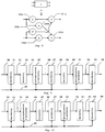
- Fig. 5 is a block diagram of an orthogonal transforming device for composing a high efficiency coding apparatus in a third embodiment of the invention. This embodiment is intended to assemble the orthogonal transforming devices 2a and 2b, and the reordering device 5 in the embodiment in Fig. 1, and realize by one orthogonal transforming device.
- numeral 20 is an input signal
- 21 is a reordering device
- 22 is a reordered output signal
- 23 is a butterfly calculation unit
- 24 is a butterfly calculation output signal
- 25 is a multiplication & butterfly calculation unit
- 26 is a multiplication & butterfly calculation output signal
- 27 is a reordering device
- 28 is a reordered output signal
- 29 is a butterfly calculation unit
- 30 is a butterfly claculation output signal
- 31 is a multiplication & butterfly calculation unit
- 32 is a multiplication & butterfly calculation output
- 33 is a reordering device
- 34 is a reordered output signal
- 35 is a changeover signal.
- the signal 35 corresponds to the changeover signal 9 in Fig. 1.
- This orthogonal transforming device is intended to transform eight pieces of data by either eight-point discrete cosine transformation, or four-point x two-point discrete cosine transformation.
- the four-point x two-point discrete cosine transformation is a two-dimensional discrete cosine transformation for performing four-point discrete cosine transformation and two-point discrete cosine transformation in independent directions.
- signal diagrams of four-point discrete cosine transformation and two-point discrete cosine transformation are shown in Fig. 6 and Fig. 7.
- the signals U1, U2, U3, U4 and U5, U6, U7, U8 after four-point x two-point discrete cosine transformation of X1+X2, X3+X4, X5+X6, X7+X8 and X1-X2, X3-X4, X5-X6, X7-X8 may be expressed in the signal diagram in Fig. 9.
- 201 and 202 are the portions for calculating the four-point discrete cosine transformation.
- the equipment compositions in jig. 7 and Fig. 9 are similar, and from this viewpoint it is the orthogonal transforming device in Fig.
- the changeover signal 35 is a signal given from outside, which changes over the eight-point discrete cosine transformation and the four-point x two-point discrete cosine transformation.
- the reordering device 21 is not necessary in the eight-point discrete cosine transformation in Fig. 7, but is needed in the four-point x two-point discrete cosine transformation in Fig. 8, and it is changed over by the changeover signal 35.
- the butterfly claculation unit 23 operates commonly in the eight-point discrete cosine transformation and four-point x two-point discrete cosine transformation.
- the multiplication & butterfly calculation unit 25 is required in part of the calculation in the eight-point discrete cosine transformation, and it is changed over by the changeover signal 35 to perfrom multiplication and butterfly calculation only when necessary. Since the reordering device 25 differs in the reordering sequence between the eight-point discrete cosine transformation and four-point x two-point discrete cosine transformation, it is changed over by the changeover signal 35 to as to reorder in specified order.
- the butterfly calculation unit 29 operates commonly in the eight-point discrete cosine transformation and four-point x two-point discrete cosine transformation.
- the multiplication & butterfly calculation unit 31 differs in the multiplier between the eight-point discrete cosine transformation and the four-point x two-point discrete cosine transformation, and it is changed over by the changeover signal 35 so as to multiply by the specified multiplier. Finally, it is reordered by the reordering device 33 to deliver the data in the sequence suited to the next calculation-or in the sequence of the magnitude of the frequency respectively in the eight-point discrete cosine transformation and four-point x two-point discrete cosine transformation, and this rearranging sequence differs between the eight-point discrete cosine transformation and four-point x two-point discrete cosine transformation, and it is selected by the changeover signal 35.
- the four-point discrete cosine transformation and the sum and difference between fields may be calculated in the calculation circuit of eight-point discrete cosine transformation
- two types of orthogonal transformation of eight-point discrete cosine transformation and four-point x two-point discrete cosine transformation may be realized in the hardware scale corresponding nearly to one circuit of eight-point discrete cosine transformation.
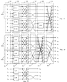
- Fig. 10 relates to a fourth embodiment, and is a block diagram of an orthogonal transforming device for performing an inverse orthogonal transformation of the orthogonal transformation shown in Fig, 5.
- numeral 40 denotes an input signal
- 41 is a reordering device
- 42 is a reordering device output signal
- 43 is a multiplication & butterfly calculation unit
- 44 is a multiplication & butterfly calculation unit output signal
- 45 is a butterfly calculation unit
- 46 is a butterfly calculation unit output signal
- 47 is a reordering device
- 48 is a reordering device output signal
- 49 is a multiplication & butterfly calculation unit
- 50 is a multiplication & butterfly calculation unit output signal
- 51 is a butterfly calculation unit
- 52 is a butterfly calculation unit output signal
- 53 is a reordering device
- 54 is a reordering device output signal
- 55 is a changeover signal.
- FIG. 10 In thus composed embodiment in Fig. 10, the operation is explained below.
- This orthogonal transforming device is intended to process eight pieces of data in either eight-point inverse discrete cosine transformation or four-point x two-point inverse discrete cosine transformation.
- Figs. 11, 12 are signal diagrams of four-point inverse discrete cosine transformation and eight-point inverse discrete cosine transformation, respectively.
- Fig. 11 is an inverse transformation of Fig. 6
- Fig. 12 is an inverse transformation of Fig. 7. However, normalizing constants are omitted.
- the calculation in Fig. 11 is same as processing 203 in Fig.
- the orthogonal transformation in Fig. 13 is a signal diagram of four-point x two-point inverse discrete cosine transformation. Comparing Fig. 12 and Fig. 13, flows of signal processing are similar, and it is the orthogonal transforming device in Fig. 10 that is designed to calculate both orthogonal transformations by one hardware. Meanwhile, the calculations corresponding to the devices in Fig. 10 are indicated by the same numbers in Fig. 12 and Fig. 13.
- the signal 55 is a changeover signal for performing either the orthogonal transformation in Fig. 12 or the orthogonal transformation in Fig.
- the input signal 40 is reordered in the data sequence in the reordering device 41. This reordering is different between the orthogonal transformations in Fig. 12 and Fig. 13, it is changed over by the changeover signal 55.
- the reordered signal 42 is multiplied, added and subtracted in the multiplication & butterfly calculation unit 43. Since the multiplier in this multiplication differs between Fig, 12 and Fig, 13, it is changed over by the changeover signal 55.
- the signal 44 is subjected to butterfly calculation commonly in Fig, 12 and Fig. 13 in the butterfly calculation unit 45.
- the signal 46 is reordered as in Fig, 12 or Fig.
- the multiplication & butterfly calculation unit 49 is required only in the eight-point discrete cosine transformation in Fig, 12, and it is changed over whether to multiply or not by the changeover signal 55.
- the signal 50 is reordered commonly in Fig. 12 and Fig. 13 by the butterfly calculation unit 51, and the data is reordered as in Fig. 12 or Fig. 13 by the command of the changeover signal 55 in the reordered device 53.
- the inverse transformation in Fig. 5 may be also realized by one orthogonal transforming device shown in Fig. 10, and the hardware is outstandingly simplified as compared with the conventional high efficiency coding apparatus requiring plural orthogonal transforming devices.
- the m-point orthogonal transforming device requires at least one more adder/substracter than the m/2-point orthogonal transforming device, and by using this adder/subtracter, two-point orthogonal transformation, that is, addition and subtraction of data can be done. Therefore, same as the orthogonal transforming device in the third embodiment or the orthogonal transforming device in the fourth embodiment, the orthogonal transforming device sharing the m-point orthogonal transformation and m/2-point x 2-point orthogonal transformation may be realized in the hardware scale almost same as the m-point orthogonal transforming device.
- the video signal possesses two time units, that is, frame and field.
- the relation of the pixel positions of frame and field is shown in Fig. 15.
- the pixels are expressed by plotting the time on the axis of abscissas and the vertical position on the axis of ordinates.
- the i-th frame (i being an integer) is composed of the i-th odd-number field and the i-th even-number field, and it must be noted that the add-number field and even-number field must be deviated in the vertical pixel position by 1/2 pixel.
- the coding efficiency may be enhanced by dividing into two sets of k1, k3, k5, ..., k m ⁇ 1, and k2, k4, k6, ..., k m to perform m/2-point x 2-point orthogonal transformation in vertical direction m/2 poitns and time-wise direction 2 points.
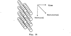
- the video signal is also strongly correlated in the horizontal direction, as shown in Fig. 16, by dividing n pixels in blocks in the horizontal direction, when the orthogonal transformation of m point x n points and orthogonal transformation of m/2 points x n points x 2 points are changedover between the quasi-still picture and moving picture, the coding efficiency is further improved.
- the sequence of the orthogonally transformed data was reordered into the sequence of low frequency by the final reordering device.
- the video signal is orthogonally transformed two-dimensionally, in the horizontal and vertical directions.
- the orthogonally transformed data can be reordered in the sequence of low two-dimensional frequency. Therefore, instead of one-dimensional transformation in the foregoing embodiments, the orthogonally transformed data may be reordered in the zigzag sequence as shown in Fig, 14 (a) or Fig, 14 (b).
Landscapes
- Engineering & Computer Science (AREA)
- Physics & Mathematics (AREA)
- General Physics & Mathematics (AREA)
- Mathematical Physics (AREA)
- Mathematical Analysis (AREA)
- Theoretical Computer Science (AREA)
- Computational Mathematics (AREA)
- Pure & Applied Mathematics (AREA)
- Mathematical Optimization (AREA)
- Signal Processing (AREA)
- Data Mining & Analysis (AREA)
- Multimedia (AREA)
- Discrete Mathematics (AREA)
- General Engineering & Computer Science (AREA)
- Software Systems (AREA)
- Databases & Information Systems (AREA)
- Algebra (AREA)
- Compression Or Coding Systems Of Tv Signals (AREA)
- Compression, Expansion, Code Conversion, And Decoders (AREA)
Applications Claiming Priority (6)
| Application Number | Priority Date | Filing Date | Title |
|---|---|---|---|
| JP193627/90 | 1990-07-20 | ||
| JP19362790A JP2605457B2 (ja) | 1990-07-20 | 1990-07-20 | 画像符号化手法 |
| JP220910/90 | 1990-08-21 | ||
| JP22091090A JP2861328B2 (ja) | 1990-08-21 | 1990-08-21 | 高能率符号化装置 |
| JP282119/90 | 1990-10-19 | ||
| JP28211990 | 1990-10-19 |
Publications (3)
| Publication Number | Publication Date |
|---|---|
| EP0467718A2 true EP0467718A2 (fr) | 1992-01-22 |
| EP0467718A3 EP0467718A3 (en) | 1992-05-13 |
| EP0467718B1 EP0467718B1 (fr) | 1996-09-11 |
Family
ID=27326792
Family Applications (1)
| Application Number | Title | Priority Date | Filing Date |
|---|---|---|---|
| EP91306625A Expired - Lifetime EP0467718B1 (fr) | 1990-07-20 | 1991-07-19 | Codeur d'images et décodeur d'images |
Country Status (3)
| Country | Link |
|---|---|
| US (1) | US5196930A (fr) |
| EP (1) | EP0467718B1 (fr) |
| DE (1) | DE69121995T2 (fr) |
Cited By (7)
| Publication number | Priority date | Publication date | Assignee | Title |
|---|---|---|---|---|
| EP0508351A3 (en) * | 1991-04-12 | 1993-12-01 | Mitsubishi Electric Corp | Method and apparatus for the motion compensated predictive coding of an image signal |
| EP0500048A3 (fr) * | 1991-02-19 | 1994-02-09 | Matsushita Electric Industrial Co Ltd | |
| EP0577365A3 (en) * | 1992-06-29 | 1996-01-03 | Sony Corp | Encoding and decoding of picture signals |
| EP0661886A3 (fr) * | 1993-12-30 | 1996-07-24 | Hewlett Packard Co | Méthode et appareil pour le décodage rapide de signaux digitaux. |
| US6226327B1 (en) | 1992-06-29 | 2001-05-01 | Sony Corporation | Video coding method and apparatus which select between frame-based and field-based predictive modes |
| EP0990992A3 (fr) * | 1998-09-28 | 2002-02-13 | Siemens Aktiengesellschaft | Processeur de calcul d'une transformée discrète/inverse-discrète du cosinus, et procédé de traitement de données |
| USRE37858E1 (en) | 1991-04-12 | 2002-09-24 | Mitsubishi Denki Kabushiki Kaisha | Motion compensation predicting encoding method and apparatus |
Families Citing this family (16)
| Publication number | Priority date | Publication date | Assignee | Title |
|---|---|---|---|---|
| US5649029A (en) * | 1991-03-15 | 1997-07-15 | Galbi; David E. | MPEG audio/video decoder |
| US5367385A (en) * | 1992-05-07 | 1994-11-22 | Picturetel Corporation | Method and apparatus for processing block coded image data to reduce boundary artifacts between adjacent image blocks |
| US5526135A (en) * | 1992-05-11 | 1996-06-11 | Sony Corporation | Video signal recording and/or reproducing apparatus operable in normal and differential speed playback modes |
| US5424778A (en) * | 1992-08-31 | 1995-06-13 | Victor Company Of Japan, Ltd. | Orthogonal transform coding apparatus and decoding apparatus |
| KR0134504B1 (ko) * | 1992-09-09 | 1998-04-23 | 배순훈 | 적응적 주파수 변환기를 가진 영상 부호화기 |
| US6078615A (en) * | 1993-03-31 | 2000-06-20 | Canon Kabushiki Kaisha | Encoding/decoding apparatus which performs an inverse orthogonal transformation on decoded data |
| KR0131715B1 (ko) * | 1994-07-25 | 1998-04-16 | 조백제 | 주사방식 변환회로 |
| US6028636A (en) * | 1994-09-30 | 2000-02-22 | Canon Kabushiki Kaisha | Image coding apparatus using detection of field correlation |
| KR0139164B1 (ko) * | 1994-12-19 | 1998-06-01 | 김광호 | 적응적 직교변환부호화 장치 |
| US6069902A (en) * | 1995-06-14 | 2000-05-30 | Matsushita Electric Industrial Co., Ltd. | Broadcast receiver, transmission control unit and recording/reproducing apparatus |
| US5832120A (en) * | 1995-12-22 | 1998-11-03 | Cirrus Logic, Inc. | Universal MPEG decoder with scalable picture size |
| JPH09200762A (ja) * | 1995-12-29 | 1997-07-31 | Daewoo Electron Co Ltd | 映像信号符号化方法及びその装置 |
| JP3168922B2 (ja) * | 1996-08-27 | 2001-05-21 | 日本ビクター株式会社 | デジタル画像情報の記録再生装置 |
| US6040861A (en) * | 1997-10-10 | 2000-03-21 | International Business Machines Corporation | Adaptive real-time encoding of video sequence employing image statistics |
| CN101951509B (zh) * | 2004-11-19 | 2012-05-23 | 松下电器产业株式会社 | 运动图像编码方法以及运动图像解码方法 |
| TWI297994B (en) * | 2005-12-08 | 2008-06-11 | Inst Information Industry | Encoder, method for adjusting decoding calculation, and computer readable record medium therefor |
Family Cites Families (6)
| Publication number | Priority date | Publication date | Assignee | Title |
|---|---|---|---|---|
| DE3304835A1 (de) * | 1983-02-11 | 1984-08-16 | Siemens AG, 1000 Berlin und 8000 München | Verfahren zur digitalen uebertragung von fernsehbildern |
| US4829465A (en) * | 1986-06-19 | 1989-05-09 | American Telephone And Telegraph Company, At&T Bell Laboratories | High speed cosine transform |
| FR2608808B1 (fr) * | 1986-12-22 | 1989-04-28 | Efcis | Circuit integre de traitement numerique de signaux |
| NL8700565A (nl) * | 1987-03-10 | 1988-10-03 | Philips Nv | Televisiesysteem waarin aan een transformatiekodering onderworpen gedigitaliseerde beeldsignalen worden overgebracht van een kodeerstation naar een dekodeerstation. |
| US4791598A (en) * | 1987-03-24 | 1988-12-13 | Bell Communications Research, Inc. | Two-dimensional discrete cosine transform processor |
| JP3085465B2 (ja) * | 1989-10-31 | 2000-09-11 | オリンパス光学工業株式会社 | 画像データの符号化装置および符号化方法 |
-
1991
- 1991-07-17 US US07/731,311 patent/US5196930A/en not_active Expired - Lifetime
- 1991-07-19 DE DE69121995T patent/DE69121995T2/de not_active Expired - Lifetime
- 1991-07-19 EP EP91306625A patent/EP0467718B1/fr not_active Expired - Lifetime
Cited By (10)
| Publication number | Priority date | Publication date | Assignee | Title |
|---|---|---|---|---|
| EP0500048A3 (fr) * | 1991-02-19 | 1994-02-09 | Matsushita Electric Industrial Co Ltd | |
| US5343501A (en) * | 1991-02-19 | 1994-08-30 | Matsushita Electric Industrial Co., Ltd. | Orthogonal transform apparatus for video signal processing |
| EP0508351A3 (en) * | 1991-04-12 | 1993-12-01 | Mitsubishi Electric Corp | Method and apparatus for the motion compensated predictive coding of an image signal |
| US5428693A (en) * | 1991-04-12 | 1995-06-27 | Mitsubishi Denki Kabushiki Kaisha | Motion compensation predicting coding method and apparatus |
| US5600737A (en) * | 1991-04-12 | 1997-02-04 | Mitsubishi Denki Kabushiki Kaisha | Motion compensation predicting encoding method and apparatus |
| USRE37858E1 (en) | 1991-04-12 | 2002-09-24 | Mitsubishi Denki Kabushiki Kaisha | Motion compensation predicting encoding method and apparatus |
| EP0577365A3 (en) * | 1992-06-29 | 1996-01-03 | Sony Corp | Encoding and decoding of picture signals |
| US6226327B1 (en) | 1992-06-29 | 2001-05-01 | Sony Corporation | Video coding method and apparatus which select between frame-based and field-based predictive modes |
| EP0661886A3 (fr) * | 1993-12-30 | 1996-07-24 | Hewlett Packard Co | Méthode et appareil pour le décodage rapide de signaux digitaux. |
| EP0990992A3 (fr) * | 1998-09-28 | 2002-02-13 | Siemens Aktiengesellschaft | Processeur de calcul d'une transformée discrète/inverse-discrète du cosinus, et procédé de traitement de données |
Also Published As
| Publication number | Publication date |
|---|---|
| HK1002135A1 (en) | 1998-07-31 |
| EP0467718B1 (fr) | 1996-09-11 |
| DE69121995D1 (de) | 1996-10-17 |
| US5196930A (en) | 1993-03-23 |
| DE69121995T2 (de) | 1997-03-20 |
| EP0467718A3 (en) | 1992-05-13 |
Similar Documents
| Publication | Publication Date | Title |
|---|---|---|
| EP0467718A2 (fr) | Codeur d'images et décodeur d'images | |
| EP0250152B1 (fr) | Circuit de transformation | |
| EP1359546B1 (fr) | Transformations bidimensionelles pour le codage d'images ou de vidéos | |
| US5703965A (en) | Image compression/decompression based on mathematical transform, reduction/expansion, and image sharpening | |
| JP5623565B2 (ja) | バタフライプロセッサを使用して離散コサイン変換をエンコードしそして計算するための装置及び方法 | |
| EP0207774A2 (fr) | Dispositif de codage en blocs | |
| Xu et al. | Lifting-based directional DCT-like transform for image coding | |
| GB2211691A (en) | Picture coding and interpolation apparatus | |
| US6317767B2 (en) | Methods and systems for performing short integer chen IDCT algorithm with fused multiply/add | |
| US6141456A (en) | Methods and apparatus for combining downsampling and inverse discrete cosine transform operations | |
| US6134571A (en) | Implicit DST-based filter operating in the DCT domain | |
| US7233623B1 (en) | Method and scalable architecture for parallel calculation of the DCT of blocks of pixels of different sizes and compression through fractal coding | |
| JPS622721A (ja) | 画像信号の符号化・復号化装置 | |
| US6181831B1 (en) | Spatial frequency-domain video signal processing | |
| US7574064B2 (en) | Fast lifting lossless wavelet transform | |
| US7577307B2 (en) | Fast adaptive lifting lossless wavelet transform | |
| US20020173952A1 (en) | Coding | |
| HK1002135B (en) | Image coding apparatus and image decoding apparatus | |
| Papadimitriou et al. | Stereo disparity analysis using phase correlation | |
| US7190847B2 (en) | Method, system, and program for fractionally shifting data subject to a previous transformation | |
| US7552160B2 (en) | Integrated lifting wavelet transform | |
| JP3907724B2 (ja) | 画像符号化装置 | |
| JP3543151B2 (ja) | データ圧縮方法及びデータ圧縮装置 | |
| JPS61294585A (ja) | 画像信号の変換符号化方式 | |
| Mietens et al. | New dct computation algorithm for video quality scaling |
Legal Events
| Date | Code | Title | Description |
|---|---|---|---|
| PUAI | Public reference made under article 153(3) epc to a published international application that has entered the european phase |
Free format text: ORIGINAL CODE: 0009012 |
|
| AK | Designated contracting states |
Kind code of ref document: A2 Designated state(s): DE FR GB NL |
|
| PUAL | Search report despatched |
Free format text: ORIGINAL CODE: 0009013 |
|
| AK | Designated contracting states |
Kind code of ref document: A3 Designated state(s): DE FR GB NL |
|
| 17P | Request for examination filed |
Effective date: 19921030 |
|
| 17Q | First examination report despatched |
Effective date: 19950228 |
|
| GRAH | Despatch of communication of intention to grant a patent |
Free format text: ORIGINAL CODE: EPIDOS IGRA |
|
| GRAH | Despatch of communication of intention to grant a patent |
Free format text: ORIGINAL CODE: EPIDOS IGRA |
|
| GRAA | (expected) grant |
Free format text: ORIGINAL CODE: 0009210 |
|
| AK | Designated contracting states |
Kind code of ref document: B1 Designated state(s): DE FR GB NL |
|
| REF | Corresponds to: |
Ref document number: 69121995 Country of ref document: DE Date of ref document: 19961017 |
|
| ET | Fr: translation filed | ||
| PLBE | No opposition filed within time limit |
Free format text: ORIGINAL CODE: 0009261 |
|
| STAA | Information on the status of an ep patent application or granted ep patent |
Free format text: STATUS: NO OPPOSITION FILED WITHIN TIME LIMIT |
|
| 26N | No opposition filed | ||
| REG | Reference to a national code |
Ref country code: GB Ref legal event code: IF02 |
|
| PGFP | Annual fee paid to national office [announced via postgrant information from national office to epo] |
Ref country code: NL Payment date: 20100716 Year of fee payment: 20 |
|
| PGFP | Annual fee paid to national office [announced via postgrant information from national office to epo] |
Ref country code: DE Payment date: 20100714 Year of fee payment: 20 Ref country code: FR Payment date: 20100805 Year of fee payment: 20 |
|
| PGFP | Annual fee paid to national office [announced via postgrant information from national office to epo] |
Ref country code: GB Payment date: 20100714 Year of fee payment: 20 |
|
| REG | Reference to a national code |
Ref country code: DE Ref legal event code: R071 Ref document number: 69121995 Country of ref document: DE |
|
| REG | Reference to a national code |
Ref country code: DE Ref legal event code: R071 Ref document number: 69121995 Country of ref document: DE |
|
| REG | Reference to a national code |
Ref country code: NL Ref legal event code: V4 Effective date: 20110719 |
|
| REG | Reference to a national code |
Ref country code: GB Ref legal event code: PE20 Expiry date: 20110718 |
|
| PG25 | Lapsed in a contracting state [announced via postgrant information from national office to epo] |
Ref country code: GB Free format text: LAPSE BECAUSE OF EXPIRATION OF PROTECTION Effective date: 20110718 |
|
| PG25 | Lapsed in a contracting state [announced via postgrant information from national office to epo] |
Ref country code: NL Free format text: LAPSE BECAUSE OF EXPIRATION OF PROTECTION Effective date: 20110719 |
|
| PG25 | Lapsed in a contracting state [announced via postgrant information from national office to epo] |
Ref country code: DE Free format text: LAPSE BECAUSE OF EXPIRATION OF PROTECTION Effective date: 20110720 |