EP0467722A1 - Haupt- und Zusatzausleger umfassender Kranausleger - Google Patents
Haupt- und Zusatzausleger umfassender Kranausleger Download PDFInfo
- Publication number
- EP0467722A1 EP0467722A1 EP91401083A EP91401083A EP0467722A1 EP 0467722 A1 EP0467722 A1 EP 0467722A1 EP 91401083 A EP91401083 A EP 91401083A EP 91401083 A EP91401083 A EP 91401083A EP 0467722 A1 EP0467722 A1 EP 0467722A1
- Authority
- EP
- European Patent Office
- Prior art keywords
- boom
- complementary
- main
- handling
- pivot axis
- Prior art date
- Legal status (The legal status is an assumption and is not a legal conclusion. Google has not performed a legal analysis and makes no representation as to the accuracy of the status listed.)
- Withdrawn
Links
- 230000000295 complement effect Effects 0.000 title claims abstract description 53
- 238000004519 manufacturing process Methods 0.000 abstract description 3
- 239000012530 fluid Substances 0.000 description 13
- 241001644893 Entandrophragma utile Species 0.000 description 6
- 230000008901 benefit Effects 0.000 description 5
- 230000005484 gravity Effects 0.000 description 4
- 238000012550 audit Methods 0.000 description 1
- 238000005452 bending Methods 0.000 description 1
- 238000010586 diagram Methods 0.000 description 1
- 238000011084 recovery Methods 0.000 description 1
- 230000000284 resting effect Effects 0.000 description 1
- 239000013589 supplement Substances 0.000 description 1
- 230000007704 transition Effects 0.000 description 1
Images




Classifications
-
- B—PERFORMING OPERATIONS; TRANSPORTING
- B66—HOISTING; LIFTING; HAULING
- B66C—CRANES; LOAD-ENGAGING ELEMENTS OR DEVICES FOR CRANES, CAPSTANS, WINCHES, OR TACKLES
- B66C23/00—Cranes comprising essentially a beam, boom, or triangular structure acting as a cantilever and mounted for translatory of swinging movements in vertical or horizontal planes or a combination of such movements, e.g. jib-cranes, derricks, tower cranes
- B66C23/62—Constructional features or details
- B66C23/64—Jibs
- B66C23/70—Jibs constructed of sections adapted to be assembled to form jibs or various lengths
- B66C23/701—Jibs constructed of sections adapted to be assembled to form jibs or various lengths telescopic
- B66C23/702—Jibs constructed of sections adapted to be assembled to form jibs or various lengths telescopic with a jib extension boom
Definitions
- the axis of pivoting of the manipulation arm relative to the support frame is placed near the underside of the complementary boom, which results in the possibility of pivoting of the manipulation arm, at from the configuration of the complementary boom in which the handling arm is placed in the extension of the support frame, only downwards.
- the only boom folding configurations complementary are similar to that shown in Figure 2 of the aforementioned European document, in which the first pivot axis can not be placed vertical. Therefore, the pivoting of the complementary boom in its folding configuration, around said first pivot axis, requires a large force, necessarily mechanized, for example that of powerful jacks.
- the invention in the context of a handling boom having the constitution defined in the preamble of claim 1, aims to allow the configuration of the folding boom configuration and the verticality of the first pivot axis to be reduced, in order to reduce the force necessary to pivot the complementary boom, folded back, around the first pivot axis, substantially only to the force making it possible to overcome the friction of said pivoting.
- the second pivot axis is arranged as specified in the characterizing part of claim 1.
- the main advantage of a boom according to the invention lies both in its ease of use and in a greater lightness of manufacture.
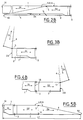
- the handling arm 4 and the support frame 2 constitute a complementary arrow 2-4, in two parts articulated around the pivot axis 5 contained substantially in the upper face S 2/4 of said complementary arrow in its deployment configuration (Figure 2B).
- This position of the pivot axis 5 makes it possible to pivot upwards (FIG. 3B) of the handling arm 4 relative to the support frame 2, from the configuration of FIG. 2B.
- the main boom 1 is substantially horizontal.
- the pivot axis 3 is vertical, while the pivot axis 5 is horizontal, transverse with respect to the main general direction D1 parallel to which extends the main boom 1.
- the handling arm 4 is oriented upwards, its free end 4A being placed in front of the pivot axis 5 so that the center of gravity G of the assembly of the support frame 2 and of the complementary arrow 4 is placed on a vertical V close to the pivot axis 3.
- the complementary general direction D4 of the manipulation arm 4 is parallel to the main direction D1, the manipulation arm 4 being oriented towards the rear. 1A of the main boom 1.
- the complementary boom constituted by the assembly of the support frame 2 and of the handling arm 4 is placed along the main boom 1, in configuration out of service, the length of the assembly being limited to the length L1 of the main boom 1.
- the general direction D2 of the support frame is parallel to the main direction D1.
- the support frame 2 has pivoted by approximately 180 ° around the vertical pivot axis 3 and its general direction is again parallel to that D1 of the main boom 1 and substantially merged with it, the support frame 2 being placed in the extension of the main boom 1, in front of the front end 1B of this main boom.
- FIGS. 5A, 5B the directions D1, D2, D4 are horizontal and parallel.
- the handling arm 4 has been replaced in the extension of the support frame 2, after pivoting around the horizontal axis 5.
- the deployment configuration of the complementary boom (2-4) is again obtained.
- the total length LT of the equipment is equal to the sum of the lengths of the main boom 1 and of the complementary boom constituted by the support frame 2 and the manipulation arm 4. This is the service configuration of the complementary arrow (2-4).
- the vertical V on which the center of gravity G is disposed has moved over a circle C of radius R centered on the axis of pivoting 3.
- the radius R is small, less than 1 m, whereas previously, when the handling arm 4 had to be moved while remaining horizontal, the radius R could in some arrows, exceed 10 m.
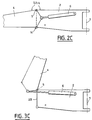
- FIGS. 2C and 3C show the complementary arrow, seen from the side, in the configurations of FIGS. 2B and 3B, respectively, as well as the jack 6 for controlling the pivoting around the axis 5.
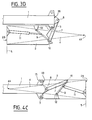
- Figures 3D and 4C show the complementary arrow, seen from above, in the configurations of Figures 3A and 4A, respectively, as well as the device for controlling the pivoting of the support frame 2 around the vertical pivot axis 3.
- the end 2B of the support frame 2, near which the pivot axis 5 of the handling arm 4 is disposed on said support frame, is located behind the front face 1B of the main boom 1 in the configuration of Figure 3D, and in front of this front face 1B in the configuration of Figure 4C.
- the spindle 13 is arranged parallel to the pivot axis 3 of the support frame 2 with respect to the main boom 1 and is constituted by two half-shafts 15 integral with the pistons 16 of two opposite jacks and capable of entering the eyes 17 formed at the front end 1B of the main boom 1 and 18 formed in the support frame 2.
- the jacks have a common chamber 19, which is connected to a conduit 20 and which, when supplied with pressurized fluid, causes the output of the half-shafts 15 and their introduction into the eyes 17 and 18, when these are opposite one another (FIGS. 4A, 4C).
- Each actuator also has a chamber 21, opposite the chamber 19, the two chambers 21 being connected by a conduit 22, itself connected to a conduit 23.
- the spindle 14 is arranged parallel to the pivot axis 5 of the handling arm 4 relative to the support frame 2 and is constituted by two half-shafts 24 integral with the pistons 25 of two opposite jacks and capable of entering the eyes 26 formed at the end 2B of the support frame and 27 formed in the manipulation arm 4.
- the jacks have a common chamber 28, which is connected to a conduit 29 and which, when supplied with pressurized fluid, causes the output of the half-shafts 24 and their introduction into the eyes 26 and 27, when these are opposite one another (FIGS. 5B, 2B).
- Each actuator also has a chamber 30, opposite the chamber 28, the two chambers 30 being connected by a conduit 31, itself connected to a conduit 32.
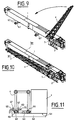
- FIGS. 9 to 11 has a constitution identical to the handling arrow of FIG. 1, to which a supplement has been added.
- This variant therefore comprises a main boom 1, telescopic, a complementary boom 2-4, itself comprising the support frame 2 pivotally mounted on the main boom 1 around the pivot axis 3, and, a handling arm 4 pivotally mounted on the support frame 2 around the pivot axis 5, all this having the characteristics already defined with reference to the preceding figures 1 to 8.
- two supports 62 of the manipulation arm 4 extend laterally on one side of the main boom 1, having their upper faces 63 located substantially in the extension of the face 64 of the main boom 1, which constitutes the lower face. of said main boom when the latter is substantially horizontal.
- the manipulation arm 4 can be supported by these supports 62, their width being sufficient to receive said handling arm.
- the upper face 63 of each support 62 is delimited by two oblique edges 66 for holding the handling arm 4 in position for wedging on the supports 62.
- each support is shaped into two plates 67 between which an upright 68 which comprises the manipulation arm 4 is capable of being disposed, each plate 67 comprising an eye 69 for receiving a removable rod 70 preventing the amount of upright 68 from leaving the two plates 67 between which it is capable of being received.
- the handling jibs described above each have a main telescopic jib 1 associated with a complementary jib 2-4 and constitute the handling equipment for mobile cranes. If the particular structure solves well the problems of size and weight of a mobile crane equipped with a telescopic main boom, it must however be observed that such a structure can be adopted in the production of fixed cranes and that the boom main may be other than telescopic: the structural advantages are effectively appreciable and sought after whatever the type of crane and / or main boom on which the complementary boom 2-4 is mounted.
- the originality of the invention lies in obtaining an R2 / R4 ratio of less than about 0.20 between the dimensions, measured in a horizontal plane (plane of FIGS. 2A; 3A), of the complementary jib 2-4 between its folding configuration (R2, FIG. 3A) and its deployment configuration (R4, FIG. 2A), the maximum overall dimensions being able to not exceed that of the crane itself.
Landscapes
- Engineering & Computer Science (AREA)
- Mechanical Engineering (AREA)
- Jib Cranes (AREA)
- Forklifts And Lifting Vehicles (AREA)
Applications Claiming Priority (2)
| Application Number | Priority Date | Filing Date | Title |
|---|---|---|---|
| FR9005575 | 1990-05-03 | ||
| FR9005575A FR2661665B1 (fr) | 1990-05-03 | 1990-05-03 | Fleche de manutention comprenant une fleche principale et une fleche complementaire. |
Publications (1)
| Publication Number | Publication Date |
|---|---|
| EP0467722A1 true EP0467722A1 (de) | 1992-01-22 |
Family
ID=9396287
Family Applications (1)
| Application Number | Title | Priority Date | Filing Date |
|---|---|---|---|
| EP91401083A Withdrawn EP0467722A1 (de) | 1990-05-03 | 1991-04-24 | Haupt- und Zusatzausleger umfassender Kranausleger |
Country Status (4)
| Country | Link |
|---|---|
| US (1) | US5140929A (de) |
| EP (1) | EP0467722A1 (de) |
| JP (1) | JP2837555B2 (de) |
| FR (1) | FR2661665B1 (de) |
Cited By (2)
| Publication number | Priority date | Publication date | Assignee | Title |
|---|---|---|---|---|
| EP0747315A4 (de) * | 1994-02-25 | 1997-06-04 | Komatsu Mfg Co Ltd | Verfahren und vorrichtung zum automatischen strecken und zusammenlegen des beweglichen auslegers eines teleskopkrans |
| EP0768274A4 (de) * | 1994-06-28 | 1997-06-04 | Komatsu Mfg Co Ltd | Verfahren und vorrichtung zum ausschieben und unterbringen eines auslegers |
Families Citing this family (13)
| Publication number | Priority date | Publication date | Assignee | Title |
|---|---|---|---|---|
| JP3258472B2 (ja) * | 1993-11-08 | 2002-02-18 | 株式会社小松製作所 | 水平ブームの張り出し、格納装置 |
| JP2000191282A (ja) * | 1998-12-28 | 2000-07-11 | Tadano Ltd | 補助ジブ付き移動式クレ―ン装置 |
| US6702132B1 (en) * | 1999-03-19 | 2004-03-09 | Link-Belt Construction Equipment Company, L.P., Lllp | Crane self-assembly system |
| JP4540788B2 (ja) * | 2000-02-14 | 2010-09-08 | 株式会社タダノ | 移動式クレーンのジブ格納装置 |
| CN1767998A (zh) * | 2003-04-02 | 2006-05-03 | 德雷克斯-德马格股份有限公司 | 桁架吊臂起重机的两件式主吊臂及其架设方法 |
| USD612565S1 (en) * | 2009-06-10 | 2010-03-23 | North Star Falcon Industries, LLC | I-beam mast |
| USD680705S1 (en) * | 2010-07-29 | 2013-04-23 | Roar Engås | Crane constructure |
| US8739988B2 (en) * | 2010-09-20 | 2014-06-03 | Manitowoc Crane Companies, Llc | Pinned connection system for crane column segments |
| US20140131300A1 (en) * | 2012-11-09 | 2014-05-15 | Gru Comedil S.R.L. | Jib for a crane |
| JP6531448B2 (ja) * | 2015-03-20 | 2019-06-19 | 株式会社タダノ | ジブ連結構造 |
| FR3046149B1 (fr) * | 2015-12-23 | 2017-12-29 | Manitowoc Crane Group France | Grue a tour a depliage et repliage automatiques et comprenant un mat et une fleche decalee par rapport au mat |
| CN108313895A (zh) * | 2018-03-29 | 2018-07-24 | 徐工集团工程机械股份有限公司 | 一种加强型组合式臂架 |
| USD1019048S1 (en) * | 2021-07-01 | 2024-03-19 | Liebherr-Werk Biberach Gmbh | Crane |
Citations (9)
| Publication number | Priority date | Publication date | Assignee | Title |
|---|---|---|---|---|
| US3360142A (en) * | 1965-08-23 | 1967-12-26 | Detroit Edison Co | Utility boom gin |
| FR2218275A1 (de) * | 1973-02-16 | 1974-09-13 | Harnischfeger Corp | |
| US4053058A (en) * | 1976-05-27 | 1977-10-11 | Fmc Corporation | Suspended extensible boom |
| FR2370677A1 (fr) * | 1976-11-15 | 1978-06-09 | Warner Swasey Co | Procede et appareil pour prolonger la fleche d'une grue |
| EP0084981A2 (de) * | 1982-01-26 | 1983-08-03 | Kabushiki Kaisha Kobe Seiko Sho | Verfahren zum Ein-und Ausklappen eines Spitzenauslegers eines beweglichen Kranes und Kran dafür |
| WO1983003816A1 (en) * | 1982-04-23 | 1983-11-10 | Kidde, Inc. | Multiple offset boom extension |
| EP0095390A1 (de) * | 1982-05-26 | 1983-11-30 | Kidde, Inc. | Sicherheitsbefestigung für seitlich verstaubare Auslegerverlängerungen oder Spitzenausleger |
| US4431109A (en) * | 1981-02-25 | 1984-02-14 | Fmc Corporation | Boom extension stowage system |
| EP0254510A1 (de) * | 1986-07-21 | 1988-01-27 | Tadano Ltd. | Auslegerverlängerung für einen Hauptausleger |
Family Cites Families (3)
| Publication number | Priority date | Publication date | Assignee | Title |
|---|---|---|---|---|
| GB1179394A (en) * | 1966-03-17 | 1970-01-28 | Winget Ltd | Mobile Load Lifting Apparatus |
| US4491229A (en) * | 1981-02-25 | 1985-01-01 | Fmc Corporation | Boom extension stowage system |
| US4621742A (en) * | 1985-01-25 | 1986-11-11 | Harnischfeger Corporation | Boom extension storage means and mechanisms |
-
1990
- 1990-05-03 FR FR9005575A patent/FR2661665B1/fr not_active Expired - Lifetime
-
1991
- 1991-04-23 US US07/690,093 patent/US5140929A/en not_active Expired - Lifetime
- 1991-04-24 EP EP91401083A patent/EP0467722A1/de not_active Withdrawn
- 1991-04-26 JP JP3097633A patent/JP2837555B2/ja not_active Expired - Lifetime
Patent Citations (9)
| Publication number | Priority date | Publication date | Assignee | Title |
|---|---|---|---|---|
| US3360142A (en) * | 1965-08-23 | 1967-12-26 | Detroit Edison Co | Utility boom gin |
| FR2218275A1 (de) * | 1973-02-16 | 1974-09-13 | Harnischfeger Corp | |
| US4053058A (en) * | 1976-05-27 | 1977-10-11 | Fmc Corporation | Suspended extensible boom |
| FR2370677A1 (fr) * | 1976-11-15 | 1978-06-09 | Warner Swasey Co | Procede et appareil pour prolonger la fleche d'une grue |
| US4431109A (en) * | 1981-02-25 | 1984-02-14 | Fmc Corporation | Boom extension stowage system |
| EP0084981A2 (de) * | 1982-01-26 | 1983-08-03 | Kabushiki Kaisha Kobe Seiko Sho | Verfahren zum Ein-und Ausklappen eines Spitzenauslegers eines beweglichen Kranes und Kran dafür |
| WO1983003816A1 (en) * | 1982-04-23 | 1983-11-10 | Kidde, Inc. | Multiple offset boom extension |
| EP0095390A1 (de) * | 1982-05-26 | 1983-11-30 | Kidde, Inc. | Sicherheitsbefestigung für seitlich verstaubare Auslegerverlängerungen oder Spitzenausleger |
| EP0254510A1 (de) * | 1986-07-21 | 1988-01-27 | Tadano Ltd. | Auslegerverlängerung für einen Hauptausleger |
Cited By (2)
| Publication number | Priority date | Publication date | Assignee | Title |
|---|---|---|---|---|
| EP0747315A4 (de) * | 1994-02-25 | 1997-06-04 | Komatsu Mfg Co Ltd | Verfahren und vorrichtung zum automatischen strecken und zusammenlegen des beweglichen auslegers eines teleskopkrans |
| EP0768274A4 (de) * | 1994-06-28 | 1997-06-04 | Komatsu Mfg Co Ltd | Verfahren und vorrichtung zum ausschieben und unterbringen eines auslegers |
Also Published As
| Publication number | Publication date |
|---|---|
| JPH0867492A (ja) | 1996-03-12 |
| FR2661665B1 (fr) | 1992-09-04 |
| US5140929A (en) | 1992-08-25 |
| FR2661665A1 (fr) | 1991-11-08 |
| JP2837555B2 (ja) | 1998-12-16 |
Similar Documents
| Publication | Publication Date | Title |
|---|---|---|
| CA2433290C (fr) | Bicyclette pliable | |
| EP0733584B1 (de) | Automatische Aufrichtvorrichtung für einen Kran mit zusammenklappbarem Ausleger | |
| EP3184481B1 (de) | Turmkran mit automatischer ein- und ausklappfunktion, der einen mast und einen zum mast versetzten ausleger umfasst | |
| FR2661665A1 (fr) | Fleche de manutention comprenant une fleche principale et une fleche complementaire. | |
| FR2682097A1 (fr) | Fleche a repliage automatise pour grue. | |
| FR2605619A1 (fr) | Engin repliable pour la manutention et le levage des charges | |
| EP1301431A1 (de) | Kran mit aus gliedern bestehendem kranarm | |
| EP0536061B1 (de) | Automatisch zusammenklappbarer Turmkran | |
| FR2550176A1 (fr) | Grue a fleche depliable en plusieurs elements articules | |
| EP0100926B1 (de) | Fahrzeug zur Handhabung von Materialien mit orientierbarem Ausleger und eingebautem Stabilisiergestell | |
| FR2765564A1 (fr) | Mature pliable en trois elements avec dispositif de pliage/depliage pour grue a tour | |
| EP1103512B1 (de) | Verstellbarer Kranausleger mit selbsttätiger Gewichtsausgleichsvorrichtung | |
| EP0870726B1 (de) | Selbstaufrichtender Kran mit seitlich zusammenklappbarem Ausleger in der Transportstellung | |
| EP4157188A1 (de) | Abnehmbares elektronisches antriebssystem für ein rollendes objekt mit automatischer richtungsblockierung | |
| EP0733583B1 (de) | Selbstaufstellender Kran mit seitlich klappbarem Ausleger | |
| EP2959759A1 (de) | Landwirtschaftliche maschine, die mit einer zentriervorrichtung ausgestattet ist | |
| EP1352870B1 (de) | Vorrichtung zum Anheben und Aufklappen von dem Mast und zum Anheben von dem Ausleger eines Kranes | |
| FR2645520A1 (fr) | Structure de levage telescopique pour un engin tel qu'une chargeuse | |
| FR2466427A1 (fr) | Grue, notamment grue de grandes dimensions | |
| EP0256304B1 (de) | Maschine für Erdarbeiten | |
| FR2673926A1 (fr) | Plate-forme elevatrice a ciseaux. | |
| FR2530116A1 (fr) | Surelevateur de balles de paille ou de foin | |
| FR2718769A1 (fr) | Ensemble compact de deux bras articulés, dont l'extrémité libre est équipée d'un porte équipement, destiné à des véhicules de manutention, et terrassement. | |
| FR2673422A1 (fr) | Dispositif de manutention d'un outil, adaptable sur un chargeur agricole. | |
| FR2579861A1 (en) | Elevator for bales of straw or hay |
Legal Events
| Date | Code | Title | Description |
|---|---|---|---|
| PUAI | Public reference made under article 153(3) epc to a published international application that has entered the european phase |
Free format text: ORIGINAL CODE: 0009012 |
|
| 17P | Request for examination filed |
Effective date: 19911109 |
|
| AK | Designated contracting states |
Kind code of ref document: A1 Designated state(s): DE ES FR GB IT |
|
| 17Q | First examination report despatched |
Effective date: 19930824 |
|
| STAA | Information on the status of an ep patent application or granted ep patent |
Free format text: STATUS: THE APPLICATION IS DEEMED TO BE WITHDRAWN |
|
| 18D | Application deemed to be withdrawn |
Effective date: 19940104 |