EP0467728B1 - Beschlag für einen Fensterflügel eines Kippfensters mit verbesserter Schliessung - Google Patents
Beschlag für einen Fensterflügel eines Kippfensters mit verbesserter Schliessung Download PDFInfo
- Publication number
- EP0467728B1 EP0467728B1 EP91401666A EP91401666A EP0467728B1 EP 0467728 B1 EP0467728 B1 EP 0467728B1 EP 91401666 A EP91401666 A EP 91401666A EP 91401666 A EP91401666 A EP 91401666A EP 0467728 B1 EP0467728 B1 EP 0467728B1
- Authority
- EP
- European Patent Office
- Prior art keywords
- fixed
- cam
- fitting device
- sash
- closure
- Prior art date
- Legal status (The legal status is an assumption and is not a legal conclusion. Google has not performed a legal analysis and makes no representation as to the accuracy of the status listed.)
- Expired - Lifetime
Links
- 230000000295 complement effect Effects 0.000 claims description 4
- 230000001154 acute effect Effects 0.000 claims description 3
- 230000000712 assembly Effects 0.000 claims 1
- 238000000429 assembly Methods 0.000 claims 1
- 241000920340 Pion Species 0.000 description 2
- 240000008042 Zea mays Species 0.000 description 1
- 230000000694 effects Effects 0.000 description 1
- 230000002349 favourable effect Effects 0.000 description 1
- 238000005096 rolling process Methods 0.000 description 1
Images


Classifications
-
- E—FIXED CONSTRUCTIONS
- E05—LOCKS; KEYS; WINDOW OR DOOR FITTINGS; SAFES
- E05D—HINGES OR SUSPENSION DEVICES FOR DOORS, WINDOWS OR WINGS
- E05D15/00—Suspension arrangements for wings
- E05D15/40—Suspension arrangements for wings supported on arms movable in vertical planes
- E05D15/44—Suspension arrangements for wings supported on arms movable in vertical planes with pivoted arms and vertically-sliding guides
-
- E—FIXED CONSTRUCTIONS
- E05—LOCKS; KEYS; WINDOW OR DOOR FITTINGS; SAFES
- E05Y—INDEXING SCHEME ASSOCIATED WITH SUBCLASSES E05D AND E05F, RELATING TO CONSTRUCTION ELEMENTS, ELECTRIC CONTROL, POWER SUPPLY, POWER SIGNAL OR TRANSMISSION, USER INTERFACES, MOUNTING OR COUPLING, DETAILS, ACCESSORIES, AUXILIARY OPERATIONS NOT OTHERWISE PROVIDED FOR, APPLICATION THEREOF
- E05Y2900/00—Application of doors, windows, wings or fittings thereof
- E05Y2900/10—Application of doors, windows, wings or fittings thereof for buildings or parts thereof
- E05Y2900/13—Type of wing
- E05Y2900/148—Windows
Definitions
- the present invention relates to window frames opening to the Italian and in particular the closing member of the hardware-support device of these frames.
- Windows with an Italian-style opening sash as described for example in document GB-A-2 225 378 and corresponding to the preamble of the first claim, in their most common form, have fitting devices made up of lateral compasses mounted on the window frame and secured to the sash.
- each guide slide is completed by a cap-shaped stop member having an obtuse angle whose point is directed upwards and whose surfaces are symmetrical with respect to one another. vertical median plane of the frame.
- This stopper cap receives in wedging, when the chassis is closed, the upper end of the compass bar which carries the chassis, this end having a nose of a shape complementary to that of said cap.
- Said stop members and upper end in the form of an associated nose of the compass have conventionally a symmetry with respect to a vertical median plane of the frame, which makes it possible to open the window frame either in one direction or the other of the closed position.
- Said nose-shaped end instead of correctly returning inside the cap, abuts on the outer surface of the cap, which consequently prevents the closure of the window and exposes you to the risk of damaging the components.
- the invention aims to remedy this drawback, in particular in the case of heavy or large windows.
- the shoeing device is in fact characterized in that it comprises, on each of its lateral shoeing elements supporting the chassis or compass, in addition to the conventional stop member in the form of a cap at the top of the slide. , a cam profile member positioned on the slide line and under said stop member, said cam profile member cooperating with a projecting element in the form of a fixed peg or rolling roller fixed on the connecting rod articulated to the slide of slide and to the support bar of the chassis, said projecting element and member with cam profile being positioned adequately with respect to each other to allow during the closing operation of the chassis the guidance in internal return when each of the lateral fittings is closed, prior to that of said complementary end nose in its stopper cap, so that the latter cannot escape from the latter r during the closing movement of the chassis.
- said end nose is replaced by a roller, possibly a pin fixed to the upper end of the compass chassis support bar, the cap corresponding stop unchanged.
- said cam profile member will be shaped so that the pin on the rod or connecting rod acts only in a limited closing stroke of the fitting element, for example in a closing angle of the frame included between 15 and 4 ° and advantageously between 5 and 10 °, the closing guidance then being taken up in continuity by the upper end of the compass guided by its stopper cap.
- the profile of said member is also in the form of a cap with an upward point and an essentially acute angle, its useful opposite faces being straight, flared or rounded slightly outward at the lower level so as to guarantee the catching of the pin of the connecting rod at closing.
- Said cam profile member is also shaped symmetrically with respect to the median vertical plane of the frame so as to allow the opening (or closing of the frame) either on one side or the other of the frame.
- said stopper cap and member with a cam profile form part of a single piece mounted integral with the associated slide.
- This same piece and the associated slide can be adjusted in height relative to a fixed point of the amount of the frame, for example by a push device fixed to the lower end of the slide, integral with the frame by said fixed point and capable of pushing said lower end of the slide, the slide and part assembly being fixed later after adjustment.
- the invention also relates to a window frame equipped with a fitting device as mentioned above.
- the fitting device according to the invention consists of two fitting elements of the compass type 1, mounted laterally on the window frame.
- the chassis is carried by the support bar 3 of each compass.
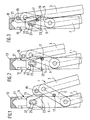
- only the upper part of a frame fitting element has been shown in different positions. We therefore see only the upper part of the frame support bar 3 with the connecting rod 5 articulated to the slide (not shown), only the upper part of the strut 7 of the compass and that the upper part of the slide 9 fixed to one of the uprights of the window frame and in which the slide moves.
- an insert 11 comprising at the upper level a stop member 13 of the upper end of the fitting element and below a member with a cam profile 15 intended to internally guide a pin 17 fixed on the connecting rod.
- the upper stop member 13 is conventional and its internal useful part 21 has the shape of an obtuse angle cap, the point of which faces upwards. The latter receives the upper end of the fitting element, namely an upper roller 19 fixed internally (FIG. 7) to the upper end of the support bar 3 of the chassis.
- the lower cam profile member receives by its internal surface said pin 17 fixed internally projecting on the connecting rod and substantially halfway along the latter. This cam profile also has a cap shape (internal surface).
- said stopper cap and cam profile have symmetry with respect to a vertical median plane of the frame or of the slide.
- said insert 11 with its stopper cap 13 and its cam profile member 15 is crimped in solidarity with the slide, the assembly being able to be positioned in an adjustable manner in height on the frame by simply tightening screws on oblong openings 25 associated so as to complete the closing of the compass and therefore of the chassis.
- This height-adjustable positioning on the amount of the frame is effected by a pusher device 26, mounted at the lower end of the slide, secured to the frame at a fixed point 28, the movement being obtained by the actuation of a screw 30 pushing that same slide.
- FIG. 1 corresponding to an angle of the chassis of 15 ° from the vertical and where the elements are well released from the part 11, the latter is gradually pushed upwards so as to evolve towards the fully closed position (at 0 ° from vertical).
- a first position for catching the pin 17 is thus obtained at an angle of approximately 10 ° from the chassis (FIG. 2) where the pin, through play and wear in the long run, is likely to come into contact with the one of the lower rounded portions 23 of the profile, to the left or to the right depending on the direction of opening of the chassis relative to the frame. Then we move to a period when the pin comes into contact with the straight part more inside the profile.
- FIG. 3 shows the case of the chassis at 7 °, substantially halfway through the pin, the upper roller 19 of the support bar is not yet caught by the upper stopper cap.
- the opening of the frame is naturally operated in reverse to what was previously mentioned for the closing, the latter being able to take place on one side or the other of the frame.
- the invention is not limited to the example described but embraces numerous variant embodiments.
- the example a part with stop member and cam profile symmetrical with respect to the median vertical plane of the frame.
- This symmetry is not compulsory and the conformations of said stop member and cam profile for the rod pin can be equally asymmetrical, which allows a greater closing stroke of the compass and therefore better closing.
- the upper roller, as well as the pin will be offset respectively with respect to the axis of the support bar and the median plane of the rod. with therefore the possibility of having elements of larger diameter and therefore favorable for better guidance.
Landscapes
- Engineering & Computer Science (AREA)
- Mechanical Engineering (AREA)
- Window Of Vehicle (AREA)
- Coating Apparatus (AREA)
- Closing And Opening Devices For Wings, And Checks For Wings (AREA)
- Wing Frames And Configurations (AREA)
- Pivots And Pivotal Connections (AREA)
- Hinges (AREA)
Claims (10)
- Beschlagsvorrichtung für Rahmen für Klappfenster, welche aus seitlichen Scherenelementen (1) besteht, die auf der Fensterzarge angebracht und mittels einer Stützstange fest mit dem Flügel verbunden sind, wobei zwei auf den vertikalen Streben der Zarge ausgebildete Schienen (9) eingreifen, in welchen jeweils ein Schieber gleitet, mit dem die oberen Scherenanlenkelmente verbunden sind, wobei die Schienen (9) einen kappenförmigen Feststeller (13 ) aufweisen, welcher das in Form eines komplementären Zapfens ausgebildete Ende des Scherenelements unter Verkeilung in der Schließstellung aufnimmt, nämlich das Ende der Stützstange (3) des Rahmens, welches am Schieber der Schiene mittels eines Verbindungs schwingarms (5) angelenkt ist, dadurch gekennzeichnet, daß sie auf jedem ihrer seitlichen Stützbeschlagselemente zur Abstützung des Rahmens bzw. der Schere (1) neben dem herkömmlichen oberen kappenförmigen Feststeller (13) oben auf der Schiene ein nockenförmigen Element (15) aufweist, das auf der Linie der Schiene und unter dem Feststeller (13) angeordnet ist, wobei das nockenförmigen Element (15) mit einem Vorsprungsteil in Form eines feststehenden Zapfens (17) oder einer Laufrolle zusammenwirkt, das auf dem am Schieber der Schiene und auf der Stützstange (3) des Rahmens angelenkten Verbindungsschwingarm (5) befestig ist, und wobei das Vorsprungteil (17) und das nockenförmige Element (15) entsprechend zueinander positioniert sind, so daß während des Schließens des Rahmens die Führung unter Rückstellung nach innen beim Schließen jedes seitlichen Beschlagselements möglich ist, und zwar vor der Rückstellung des komplemantären Zapfens am Ende in die entsprechende Feststellkappe (13), so daß dieser nicht bei der Schließbewegung des Rahmens an letzterer ausweichen kann.
- Beschlagsvorrichtung nach Anspruch 1, dadurch gekennzeichnet, daß der Vorsprung am Ende als Rolle (19) bzw. als Zapfen ausgebildet ist, die bzw. Der am oberen Ende der Stützstange (3) des Scherenrahmens befestig ist.
- Beschlagsvorrichtung nach Anspruch 1 oder 2, dadurch gekennzeichnet, daß das nockenförmige Element (15) so ausgebildet ist, daß der Zapfen (17) auf dem Verbindungsschwingarm (5) nur über einen begrenzten Schließhub des Beschlagselements wirksam ist, beispielweise innerhalb eines Rahmenschließwinkels zwischen 15 und 4° wobei die Führung beim Schließen anschließend übergangslos vom oberen Ende (19) der von der zugehörigen Feststellkappe geführten Schere (1) übernommen wird.
- Beschlagsvorrichtung nach Anspruch 3, dadurch gekennzeichnet, daß der Zapfen (17) über einen Scließhub des Rahmens zwischen 10 und 5° wirksam ist.
- Beschlagsvorrichtung nach einem der vorhergehenden Ansprüche, dadurch gekennzeichnet, daß das nockenförmige Element (15) symmetrisch zur vertikalen Mittelebene der Zarge so ausgebildet ist, daß das Öffnen bzw. Schließen des Rahmens gleichermaßen zur einen oder anderen Seite der Zarge möglich ist.
- Beschlagsvorrichtung nach einem der vorhergehenden Ansprüche, dadurch gekennzeichnet, daß das elementes (15) ein inneres Nockenprofil in Form einer Kappe mit nach oben weisender Spitze (27) und im wesentlichen spitzem Winkel aufweist, wobei deren gegenüberliegenden Wirkflächen gerade, aufgeweitet oder auf der unteren Höhe leicht nach außen so abgerundet ist, daß ein Einfangen des Zapfens (17) des Verbindungsschwingarms beim Schließen gewährleistet ist.
- Beschlagsvorrichtung nach einem der vorhergehenden Ansprüche, dadurch gekennzeichnet, daß die feststellkappe (13) und das nockenförmige Element (15) Bestandteil ein und desselben oberhalb jeder Gleitschiene (9) befestigten Teils (11) sind.
- Beschlagsvorrichtung nach Anspruch 7,dadurch gekennzeichnet, daß das Teil (11) fest an der Schiene (9) befestigt, beispielsweise am oberen Ende der Schiene angefalzt ist, wobei das wobei die gesamte Anordnung aus dem Teil (11) und der Schiene (9) über eine Schiebervorrichtung (26) mit Schraube (30) höhenverstellbar ist, welche am unteren Ende der Schiene fest mit der Zarge über einen festen Punkt (28) verbunden positioniert ist und das untere Ende der Schiene durch Betätigung der Schraube drücken kann, und wobei die gesamte Anordnung nach nach Einstellung auf der Zarge fixiert wird.
- Beschlagsvorrichtung nach Anspruch 1, dadurch gekennzeichnet, daß der Feststeller (13) und das Nockenprofil (15) gegenüber der Vertikaler Mittelebene der Zarge asymmetrisch sind.
- Fensterrahmen für Klappfenster, dadurch gekennzeichnet, daß er eine Beschlagsvorrichtung mit seitlicher Schere (1) aufweist, wir er in einem der vorhergehenden Ansprüche umrissen ist.
Applications Claiming Priority (2)
| Application Number | Priority Date | Filing Date | Title |
|---|---|---|---|
| FR9009323A FR2664934B1 (fr) | 1990-07-20 | 1990-07-20 | Dispositif de ferrage pour chassis de fenetre ouvrant a l'italienne a fermeture perfectionnee. |
| FR9009323 | 1990-07-20 |
Publications (2)
| Publication Number | Publication Date |
|---|---|
| EP0467728A1 EP0467728A1 (de) | 1992-01-22 |
| EP0467728B1 true EP0467728B1 (de) | 1993-02-24 |
Family
ID=9398954
Family Applications (1)
| Application Number | Title | Priority Date | Filing Date |
|---|---|---|---|
| EP91401666A Expired - Lifetime EP0467728B1 (de) | 1990-07-20 | 1991-06-20 | Beschlag für einen Fensterflügel eines Kippfensters mit verbesserter Schliessung |
Country Status (6)
| Country | Link |
|---|---|
| EP (1) | EP0467728B1 (de) |
| AT (1) | ATE86003T1 (de) |
| DE (1) | DE69100036T2 (de) |
| DK (1) | DK0467728T3 (de) |
| ES (1) | ES2040144T3 (de) |
| FR (1) | FR2664934B1 (de) |
Families Citing this family (9)
| Publication number | Priority date | Publication date | Assignee | Title |
|---|---|---|---|---|
| FR2690196B1 (fr) * | 1992-04-17 | 1996-01-19 | Bezault Sa | Dispositif de ferrage pour chassis de fenetre ouvrant a l'italienne a fermeture perfectionnee. |
| FR2690198A1 (fr) * | 1992-04-21 | 1993-10-22 | Bezault Sa | Dispositif de ferrage pour châssis de fenêtre ouvrant à l'italienne à fermeture perfectionnée. |
| FR2690197B1 (fr) * | 1992-04-21 | 1996-01-19 | Bezault Sa | Dispositif de ferrage pour chassis de fenetre ouvrant a l'italienne a fermeture perfectionnee. |
| FR2694041A1 (fr) * | 1992-07-23 | 1994-01-28 | Belaz Andre | Compas pour ouvrant projetant articulé. |
| FR2697048B1 (fr) * | 1992-10-19 | 1994-12-09 | Ferco Int Usine Ferrures | Compas-charnière pour fenêtre à l'italienne. |
| GB2313402A (en) * | 1996-04-19 | 1997-11-26 | Dgs Hardware Ltd | Apparatus for locating a support track of a stay |
| WO1998018299A2 (en) * | 1996-10-22 | 1998-04-30 | Securistyle Limited | Hinges and parts thereof |
| GB2322161B (en) * | 1997-02-18 | 2000-10-25 | Securistyle Ltd | Locating block |
| US5898977A (en) * | 1997-09-25 | 1999-05-04 | Advantage Manufacturing Corp., Inc. | Non-handed in-line window supporting bracket |
Family Cites Families (3)
| Publication number | Priority date | Publication date | Assignee | Title |
|---|---|---|---|---|
| FR2554860B1 (fr) * | 1983-11-10 | 1988-04-29 | Bezault Sa | Dispositif perfectionne de ferrage pour chassis ouvrant a l'italienne |
| US5081741A (en) * | 1988-10-11 | 1992-01-21 | Ferco International Usine De Ferrures De Batiment | Hinge fittings for pivoting and tiltable doors, windows or the like, situated in rabbets of the opening frame and the fixed frame |
| GB2225378B (en) * | 1988-10-18 | 1992-05-20 | Walfab Limited | Improvements in hinges |
-
1990
- 1990-07-20 FR FR9009323A patent/FR2664934B1/fr not_active Expired - Lifetime
-
1991
- 1991-06-20 DE DE9191401666T patent/DE69100036T2/de not_active Expired - Fee Related
- 1991-06-20 DK DK91401666.2T patent/DK0467728T3/da active
- 1991-06-20 EP EP91401666A patent/EP0467728B1/de not_active Expired - Lifetime
- 1991-06-20 AT AT91401666T patent/ATE86003T1/de not_active IP Right Cessation
- 1991-06-20 ES ES199191401666T patent/ES2040144T3/es not_active Expired - Lifetime
Also Published As
| Publication number | Publication date |
|---|---|
| EP0467728A1 (de) | 1992-01-22 |
| ES2040144T3 (es) | 1993-10-01 |
| DE69100036T2 (de) | 1993-07-15 |
| DE69100036D1 (de) | 1993-04-01 |
| FR2664934B1 (fr) | 1992-11-20 |
| ATE86003T1 (de) | 1993-03-15 |
| DK0467728T3 (da) | 1993-04-05 |
| FR2664934A1 (fr) | 1992-01-24 |
Similar Documents
| Publication | Publication Date | Title |
|---|---|---|
| BE1004838A3 (fr) | Dispositif d'actionnement de fenetre et structure a charniere. | |
| FR2573364A1 (fr) | Toit coulissant, notamment pour vehicule | |
| EP1227948B1 (de) | Tankverschlussdeckel für kraftfahrzeug | |
| EP0467728A1 (de) | Beschlag für einen Fensterflügel eines Kippfensters mit verbesserter Schliessung | |
| FR2712337A1 (fr) | Dispositif de verrouillage à au moins un point de condamnation. | |
| FR2722527A1 (fr) | Dispositif de verrouillage pour chassis a frappe | |
| FR2738867A1 (fr) | Porte battante a articulation integree | |
| FR2514398A1 (fr) | Dispositif pour l'actionnement d'un entrebailleur pour les vantaux de fenetres, portes, etc. | |
| EP0012677B1 (de) | Gefälle regulierende, einstellbare Türangel | |
| FR2703720A1 (fr) | Dispositif de verrouillage automatique d'une porte, en particulier d'une porte basculante. | |
| FR2519060A1 (fr) | Dispositif de verrouillage pour portail | |
| FR2520038A1 (fr) | Dispositif entrebailleur pour battant de porte ou de fenetre | |
| EP0377545B1 (de) | Schiebeflügel | |
| FR2551410A1 (fr) | Wagon de marchandises couvert a parois laterales constituees chacune d'au moins deux elements de paroi mobiles | |
| FR3068062A1 (fr) | Dispositif de blocage | |
| EP0924377B1 (de) | Scharnierbeschlag für Tür, Fenster oder dgl | |
| FR2509778A1 (fr) | Fenetre a vantail tournant et basculant | |
| FR2656372A1 (fr) | Mecanisme de verrouillage d'un store mecanique. | |
| EP0928871B1 (de) | Verbesserung der gelenkigen Verbindung eines Flügels an einem Rahmen | |
| FR2690197A1 (fr) | Dispositif de ferrage pour châssis de fenêtre ouvrant à l'Italienne à fermeture perfectionnée. | |
| FR2667565A1 (fr) | Pedalier a manivelles de longueur fixe ou variable pour cycles. | |
| FR2690196A1 (fr) | Dispositif de ferrage pour châssis de fenêtre ouvrant à l'italienne à fermeture perfectionnée. | |
| FR2697865A1 (fr) | Compas-charnière pour fenêtre à l'italienne. | |
| FR2739652A1 (fr) | Perfectionnement pour porte coulissante | |
| FR2518627A1 (fr) | Dispositif de surete contre les fausses manoeuvres |
Legal Events
| Date | Code | Title | Description |
|---|---|---|---|
| PUAI | Public reference made under article 153(3) epc to a published international application that has entered the european phase |
Free format text: ORIGINAL CODE: 0009012 |
|
| AK | Designated contracting states |
Kind code of ref document: A1 Designated state(s): AT BE CH DE DK ES GB IT LI NL SE |
|
| 17P | Request for examination filed |
Effective date: 19920217 |
|
| 17Q | First examination report despatched |
Effective date: 19920630 |
|
| GRAA | (expected) grant |
Free format text: ORIGINAL CODE: 0009210 |
|
| ITF | It: translation for a ep patent filed | ||
| AK | Designated contracting states |
Kind code of ref document: B1 Designated state(s): AT BE CH DE DK ES GB IT LI NL SE |
|
| REF | Corresponds to: |
Ref document number: 86003 Country of ref document: AT Date of ref document: 19930315 Kind code of ref document: T |
|
| REF | Corresponds to: |
Ref document number: 69100036 Country of ref document: DE Date of ref document: 19930401 |
|
| REG | Reference to a national code |
Ref country code: DK Ref legal event code: T3 |
|
| GBT | Gb: translation of ep patent filed (gb section 77(6)(a)/1977) |
Effective date: 19930305 |
|
| REG | Reference to a national code |
Ref country code: ES Ref legal event code: FG2A Ref document number: 2040144 Country of ref document: ES Kind code of ref document: T3 |
|
| PLBE | No opposition filed within time limit |
Free format text: ORIGINAL CODE: 0009261 |
|
| STAA | Information on the status of an ep patent application or granted ep patent |
Free format text: STATUS: NO OPPOSITION FILED WITHIN TIME LIMIT |
|
| 26N | No opposition filed | ||
| EAL | Se: european patent in force in sweden |
Ref document number: 91401666.2 |
|
| EUG | Se: european patent has lapsed | ||
| REG | Reference to a national code |
Ref country code: GB Ref legal event code: IF02 |
|
| PGFP | Annual fee paid to national office [announced via postgrant information from national office to epo] |
Ref country code: SE Payment date: 20060614 Year of fee payment: 16 Ref country code: NL Payment date: 20060614 Year of fee payment: 16 |
|
| PGFP | Annual fee paid to national office [announced via postgrant information from national office to epo] |
Ref country code: GB Payment date: 20060615 Year of fee payment: 16 Ref country code: CH Payment date: 20060615 Year of fee payment: 16 Ref country code: DK Payment date: 20060615 Year of fee payment: 16 |
|
| PGFP | Annual fee paid to national office [announced via postgrant information from national office to epo] |
Ref country code: AT Payment date: 20060616 Year of fee payment: 16 Ref country code: DE Payment date: 20060616 Year of fee payment: 16 |
|
| PGFP | Annual fee paid to national office [announced via postgrant information from national office to epo] |
Ref country code: ES Payment date: 20060629 Year of fee payment: 16 |
|
| PGFP | Annual fee paid to national office [announced via postgrant information from national office to epo] |
Ref country code: IT Payment date: 20060630 Year of fee payment: 16 |
|
| PGFP | Annual fee paid to national office [announced via postgrant information from national office to epo] |
Ref country code: BE Payment date: 20060712 Year of fee payment: 16 |
|
| BERE | Be: lapsed |
Owner name: *BEZAULT Effective date: 20070630 |
|
| REG | Reference to a national code |
Ref country code: CH Ref legal event code: PL |
|
| REG | Reference to a national code |
Ref country code: DK Ref legal event code: EBP |
|
| EUG | Se: european patent has lapsed | ||
| GBPC | Gb: european patent ceased through non-payment of renewal fee |
Effective date: 20070620 |
|
| PG25 | Lapsed in a contracting state [announced via postgrant information from national office to epo] |
Ref country code: AT Free format text: LAPSE BECAUSE OF NON-PAYMENT OF DUE FEES Effective date: 20070620 |
|
| NLV4 | Nl: lapsed or anulled due to non-payment of the annual fee |
Effective date: 20080101 |
|
| PG25 | Lapsed in a contracting state [announced via postgrant information from national office to epo] |
Ref country code: BE Free format text: LAPSE BECAUSE OF NON-PAYMENT OF DUE FEES Effective date: 20070630 |
|
| PG25 | Lapsed in a contracting state [announced via postgrant information from national office to epo] |
Ref country code: DE Free format text: LAPSE BECAUSE OF NON-PAYMENT OF DUE FEES Effective date: 20080101 Ref country code: NL Free format text: LAPSE BECAUSE OF NON-PAYMENT OF DUE FEES Effective date: 20080101 Ref country code: CH Free format text: LAPSE BECAUSE OF NON-PAYMENT OF DUE FEES Effective date: 20070630 Ref country code: LI Free format text: LAPSE BECAUSE OF NON-PAYMENT OF DUE FEES Effective date: 20070630 |
|
| PG25 | Lapsed in a contracting state [announced via postgrant information from national office to epo] |
Ref country code: GB Free format text: LAPSE BECAUSE OF NON-PAYMENT OF DUE FEES Effective date: 20070620 |
|
| PG25 | Lapsed in a contracting state [announced via postgrant information from national office to epo] |
Ref country code: SE Free format text: LAPSE BECAUSE OF NON-PAYMENT OF DUE FEES Effective date: 20070621 |
|
| PG25 | Lapsed in a contracting state [announced via postgrant information from national office to epo] |
Ref country code: DK Free format text: LAPSE BECAUSE OF NON-PAYMENT OF DUE FEES Effective date: 20070702 |
|
| REG | Reference to a national code |
Ref country code: ES Ref legal event code: FD2A Effective date: 20070621 |
|
| PG25 | Lapsed in a contracting state [announced via postgrant information from national office to epo] |
Ref country code: ES Free format text: LAPSE BECAUSE OF NON-PAYMENT OF DUE FEES Effective date: 20070621 |
|
| PG25 | Lapsed in a contracting state [announced via postgrant information from national office to epo] |
Ref country code: IT Free format text: LAPSE BECAUSE OF NON-PAYMENT OF DUE FEES Effective date: 20070620 |