EP0467879A2 - Transmission pour tracteur avec dispositif de changement de vitesse - Google Patents
Transmission pour tracteur avec dispositif de changement de vitesse Download PDFInfo
- Publication number
- EP0467879A2 EP0467879A2 EP91890154A EP91890154A EP0467879A2 EP 0467879 A2 EP0467879 A2 EP 0467879A2 EP 91890154 A EP91890154 A EP 91890154A EP 91890154 A EP91890154 A EP 91890154A EP 0467879 A2 EP0467879 A2 EP 0467879A2
- Authority
- EP
- European Patent Office
- Prior art keywords
- shift
- shaft
- transmission
- pivot axis
- coupling rod
- Prior art date
- Legal status (The legal status is an assumption and is not a legal conclusion. Google has not performed a legal analysis and makes no representation as to the accuracy of the status listed.)
- Granted
Links
Images
Classifications
-
- F—MECHANICAL ENGINEERING; LIGHTING; HEATING; WEAPONS; BLASTING
- F16—ENGINEERING ELEMENTS AND UNITS; GENERAL MEASURES FOR PRODUCING AND MAINTAINING EFFECTIVE FUNCTIONING OF MACHINES OR INSTALLATIONS; THERMAL INSULATION IN GENERAL
- F16H—GEARING
- F16H59/00—Control inputs to control units of change-speed- or reversing-gearings for conveying rotary motion
- F16H59/02—Selector apparatus
- F16H59/04—Ratio selector apparatus
- F16H59/042—Ratio selector apparatus comprising a final actuating mechanism
-
- B—PERFORMING OPERATIONS; TRANSPORTING
- B60—VEHICLES IN GENERAL
- B60K—ARRANGEMENT OR MOUNTING OF PROPULSION UNITS OR OF TRANSMISSIONS IN VEHICLES; ARRANGEMENT OR MOUNTING OF PLURAL DIVERSE PRIME-MOVERS IN VEHICLES; AUXILIARY DRIVES FOR VEHICLES; INSTRUMENTATION OR DASHBOARDS FOR VEHICLES; ARRANGEMENTS IN CONNECTION WITH COOLING, AIR INTAKE, GAS EXHAUST OR FUEL SUPPLY OF PROPULSION UNITS IN VEHICLES
- B60K20/00—Arrangement or mounting of change-speed gearing control devices in vehicles
- B60K20/02—Arrangement or mounting of change-speed gearing control devices in vehicles of initiating means
- B60K20/04—Arrangement or mounting of change-speed gearing control devices in vehicles of initiating means floor mounted
Definitions
- the invention relates to a transmission for a tractor with a gear shifting device, which consists of a rotatable and displaceable shift shaft protruding laterally from the transmission, and a shift lever arranged outside the transmission.
- gearshift devices are called side shifts and are used in tractors to avoid the uncomfortable arrangement of the shift lever between the driver's knees.
- the shift lever is usually located on the right side of the driver.
- gearshift shaft has been connected by a mechanism to a gearshift lever attached to the cabin floor.
- a mechanism can be seen, for example, in DE-OS 21 28 172.
- a crank arm is formed at the outer end of the shift shaft, into which the lowermost end of the shift lever, which is mounted somewhat above in a shift ball attached to the cabin floor, engages.
- either the lower end of the shift lever must be connected to the crank arm of the shift shaft via a sliding joint, or, if the sliding joint between the crank and shift lever is to be avoided, the shift lever itself in the shift ball must be movable up and down in its longitudinal direction .
- the shift lever is connected to the shift shaft by means of a shift joint which has a single pivot axis lying essentially in the longitudinal direction of the transmission, and to the transmission housing or a part fastened to it by means of a coupling rod and ball joints.
- the gearshift lever Due to the gearshift joint with only one swivel axis in the longitudinal direction of the gearbox, the gearshift lever is connected directly and practically without friction with respect to the rotational movement of the gearshift shaft (which leads to the gears being engaged). Since neither a ball joint, nor a sliding joint, nor an anti-rotation device is required, the switching movement is smooth and precise.
- the gearshift lever is connected directly to the gearbox via the gearshift shaft and forms a ready-to-install unit with a minimum of components. Relative movements between gearbox and cabin do not affect the gearshift at all.
- the coupling rod is arranged approximately horizontally under the selector shaft and connected to the lower end of the selector lever.
- the shift lever acts as a one-armed lever when selecting the shift gate, which results in a long lever arm for a certain length of the entire shift lever.
- the gear lever acts as a crank, and the coupling rod is slightly deflected.
- the path of the shift knob at the upper end of the shift lever only deviates slightly from the straight line, although the coupling rod is only short when the ball joint, which forms the pivot point on the housing, is located under the selector shaft. Finally, the coupling rod is arranged well protected next to the gear.
- the ball joint which forms the articulation point of the coupling rod on the transmission housing, can lie outside the plane spanned by the selector shaft and shift lever, as seen in the direction of travel, behind or in front of it.
- the path of the shift knob runs forward-in or forward-outward during the engagement movement, which is more ergonomically advantageous, and the coupling rod can be made longer, as a result of which the path of the shift cannon is even less of the straight line deviates.
- the gearshift joint consists of a fork-shaped body with eyes fixedly connected to the gearshift shaft, in which the pivot axis of the gearshift lever is mounted, so that the pivot axis and its mounting can be dimensioned such that even high torques when a gear is engaged a synchronized transmission sometimes occur, can be entered largely without play in the shift shaft.
- the pivot axis is mounted in the eyes by means of bearings made of torsionally soft, hollow cylindrical rubber parts, the rubber bearing comprising an inner metal sleeve and an outer metal sleeve, and the inner sleeve being firmly connected to the pivot axis and the outer sleeve being firmly connected to the eye .
- pivot axis consists of a transverse threaded pipe piece which is firmly connected to the shift lever and has screws arranged on both sides, which non-positively connect the inner sleeves of the rubber bearings to the threaded pipe piece.
- the lateral deflection of the Sohwenkachse in the rubber bearing can be limited by stop rings attached in the interior of the eyes. A hard shift feeling is achieved, but the shift lever is still vibration-insulated when it is unloaded or only slightly loaded.
- the rubber bearings are pretensioned in the circumferential direction, by means of which the shift lever always returns to a preferred shift gate in the idle position, and the tension spring usually provided for this purpose, often even outside of the gear housing, can be dispensed with.
- the invention naturally also deals with a tractor transmission consisting of a manual transmission and a group transmission with several circuits according to the invention.
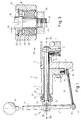
- the transmission with the switching device according to the invention is only partially shown in FIGS. 1 and 2. It consists of a gearbox housing 1 with gearbox cover 2, in which the various shafts (not shown) with gearwheels and shift fork 11 are located in the longitudinal direction 35 of the gearbox. In this respect, it is a completely conventional transmission as used in tractors. In the interior of the transmission housing there are furthermore shift rods 9 arranged parallel to the transmission shafts with drivers 8, in which a shift finger 7 engages. In order to enable the lateral arrangement of the shift lever, a shift shaft 6 is arranged transversely to the direction of the shift rods 9, on which the shift finger or several shift fingers 7 are fixed.
- the selector shaft is rotatably and displaceably mounted in a guide tube 5, which is part of a shift bracket 3 screwed to the transmission housing 1 by means of a base plate 4 and screws 14. It can also be stored in the other side wall of the drive, not shown.
- the switching device consists of the switching shaft 6, a switching joint 10, a switching lever 11 and a coupling rod 13.
- the switching shaft 6 is mounted in the guide tube 5 and is sealed by a sealing ring 22 and a scraper ring 21 and protrudes therefrom.
- the selector shaft 6 there is the selector joint 10, the fork-shaped body 23 of which is firmly connected to the outer end of the selector shaft, for example by welding, and forms a cup-shaped deflector 24 which engages over a collar 20 of the guide tube 5.
- eyes 25 are formed, in which the pivot axis 36 is mounted in a manner to be described.
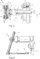
- the pivot axis 36 as can be seen in FIG.
- the shift lever 11 consists of a threaded tube piece 26, which is penetrated by the shift lever 11 and is firmly connected to it, for example by welding, and rubber bearings 28 are fastened to its two end faces by means of screws 27.
- the shift lever 11 is pivotable about this pivot axis 36. It continues beyond this pivot axis 36 in the lower part 12, at the end of which there is a ball head 17 which is articulated to an articulated head 15 of the coupling rod 13.
- the other joint head 16 of the coupling rod 13 engages over a ball head 18, which is fastened to the base plate 4 of the switching console 3, but could also be fastened to the gear housing 1 itself.
- the shift lever is thus guided precisely and largely without friction on the transmission itself.
- the coupling rod 13 is approximately parallel to the selector shaft 6 and selector shaft 6, the shift lever 11 and the coupling rod 13 lie approximately in a vertical plane.
- the shift knob 37 moves transversely to the direction of travel, i.e. in the direction of displacement of the shift shaft 6, the shift lever 11, 12 acts as a one-armed lever, the lower joint head 15 of which is supported via the coupling rod 13 on the shift console 3 and thus on the housing 1, and the the pivot axis 36 of the shift joint 10 moves the shift shaft 6, whereby the shift finger 7 at the other end of the shift shaft 6 engages in one or the other driver 8 ', whereby the shift gate is selected.
- the shift lever 11 acts on the shift shaft 6 like a crank via the pivot axis 36.
- the ball head 17 at the lower end of the shift lever 12 is laterally deflected thereby, whereby the shift lever is also pivoted slightly to the side in the transverse direction.
- this deviation is generally not noticed by the driver.
- the rubber bearing consists of a hollow cylindrical rubber body 28 which is curved inwards at the front edges and which is delimited by an inner sleeve 29 and an outer sleeve 30.
- the inner sleeve 29 is clamped by the head 38 of the screw 27 against the threaded tube piece 26.
- the outer sleeve 30 is pressed into the eye 25.
- both sleeves 29, 30 of the rubber bearing 28 are also connected in a rotationally fixed manner to the pivot axis 36 or the eye 25, so that during the pivoting movement of the shift lever 11 in the transverse direction, the change in angle between the shift lever 11 and the shift shaft 6 and the consequent rotation of the two sleeves 29, 30 against each other is received by the rubber body 28.
- the rubber bearing described is a customary, large-volume and therefore inexpensive machine element with high wear resistance.
- a stop ring 31 is arranged in the eye 25 which, after overcoming a play 39 on the head 38 of the screw 27 is applied and thus limits the movement. To secure this stop ring 31 is still axially fixed with a spring ring 32.
- the procedure is as follows: the rubber bearing 28 is pressed into the eye 25 with its outer ring 30 and, if necessary, the rings 31, 32 are mounted in both eyes. Then the Gexin pipe piece 26, which is already firmly connected to the shift lever, is inserted between the inner sleeves 29 and the two screws 27 are inserted from the outside. Then the two rod ends 15, 16 of the coupling rod 13 are clipped onto the ball heads 17, 18 and finally the screws 27 are tightened.
- the shift lever is now installed. If the rubber bearing 28 is to be installed with pretension, the assembly process according to FIG. 4 proceeds as follows: The shift lever 11 is clamped in the position 11 'shown there, i.e. before the joint head 15 is placed on the ball head 18, by means of the screws 27 and only then - and this creates the preload - is the joint head 16 pulled to the right (arrow 40) and clipped onto the ball head 18.
- the coupling rod 13 can also be arranged above the selector shaft 6 and connected to a ball head 18 attached to the housing 1 or housing cover 2 above the selector shaft, as a result of which the selector lever 11 acts as a one-armed lever in both directions of movement.
- This can be advantageous, for example, when the length of the shift rods changes, for example when changing the shift pattern in an existing transmission.
- the kinematic conditions can be adapted to various constructional and ergonomic requirements by suitable selection of the dimensions, angles and shapes of the parts of the kinematic chain 6, 11, 12, 13, 1.
- the shift lever 11 can have any shape, that is to say it can also be strongly curved.
- the shift shaft 6 does not necessarily have to be arranged horizontally.
- a transmission with a plurality of shift levers with a switching device according to the invention is also within the scope of the invention.
Landscapes
- Engineering & Computer Science (AREA)
- General Engineering & Computer Science (AREA)
- Mechanical Engineering (AREA)
- Gear-Shifting Mechanisms (AREA)
- Arrangement Or Mounting Of Control Devices For Change-Speed Gearing (AREA)
- Structure Of Transmissions (AREA)
Applications Claiming Priority (2)
| Application Number | Priority Date | Filing Date | Title |
|---|---|---|---|
| DE4023189 | 1990-07-20 | ||
| DE4023189A DE4023189A1 (de) | 1990-07-20 | 1990-07-20 | Getriebe fuer zugmaschinen mit gangschaltvorrichtung |
Publications (3)
| Publication Number | Publication Date |
|---|---|
| EP0467879A2 true EP0467879A2 (fr) | 1992-01-22 |
| EP0467879A3 EP0467879A3 (en) | 1992-04-15 |
| EP0467879B1 EP0467879B1 (fr) | 1995-05-17 |
Family
ID=6410734
Family Applications (1)
| Application Number | Title | Priority Date | Filing Date |
|---|---|---|---|
| EP91890154A Expired - Lifetime EP0467879B1 (fr) | 1990-07-20 | 1991-07-17 | Transmission pour tracteur avec dispositif de changement de vitesse |
Country Status (3)
| Country | Link |
|---|---|
| EP (1) | EP0467879B1 (fr) |
| AT (1) | ATE122763T1 (fr) |
| DE (2) | DE4023189A1 (fr) |
Families Citing this family (1)
| Publication number | Priority date | Publication date | Assignee | Title |
|---|---|---|---|---|
| KR20180053074A (ko) * | 2016-11-11 | 2018-05-21 | 엘에스엠트론 주식회사 | 차량용 변속 레버 기구 |
Family Cites Families (7)
| Publication number | Priority date | Publication date | Assignee | Title |
|---|---|---|---|---|
| DE1991350U (de) * | 1968-08-08 | Gebr Eicher Traktoren- und Landmaschinen-Werke, 8011 Forstern | Seitlich vom Fahrersitz angeordnete Schaltvorrichtung fur Zugmaschmengetriebe, insbesondere fur Schleppergetriebe | |
| DE1038416B (de) * | 1956-06-28 | 1958-09-04 | Lemfoerder Metallwaren G M B H | Federbuchse, insbesondere zum Lagern des Federbolzens bei Federaufhaengungen von Kraftfahrzeugen |
| FR1238820A (fr) * | 1959-07-07 | 1960-08-19 | Renault | Dispositif de commande à liaison souple pour boîte de vitesses |
| SE348148B (fr) * | 1970-11-23 | 1972-08-28 | Saab Scania Ab | |
| DE2128172B2 (de) * | 1971-06-07 | 1976-06-10 | Schaltvorrichtung fuer ein aus einem hauptgetriebe, einem gruppengetriebe und einem wendegetriebe bestehendes zahnradwechselgetriebe von ackerschleppern o.dgl. | |
| FR2217943A5 (fr) * | 1973-02-08 | 1974-09-06 | Peugeot & Renault | |
| US4305308A (en) * | 1979-12-20 | 1981-12-15 | Allis-Chalmers Corporation | Side mounted transmission shifting mechanism |
-
1990
- 1990-07-20 DE DE4023189A patent/DE4023189A1/de active Granted
-
1991
- 1991-07-17 DE DE59105496T patent/DE59105496D1/de not_active Expired - Fee Related
- 1991-07-17 AT AT91890154T patent/ATE122763T1/de not_active IP Right Cessation
- 1991-07-17 EP EP91890154A patent/EP0467879B1/fr not_active Expired - Lifetime
Also Published As
| Publication number | Publication date |
|---|---|
| EP0467879A3 (en) | 1992-04-15 |
| DE59105496D1 (de) | 1995-06-22 |
| DE4023189A1 (de) | 1992-01-23 |
| EP0467879B1 (fr) | 1995-05-17 |
| ATE122763T1 (de) | 1995-06-15 |
| DE4023189C2 (fr) | 1992-07-09 |
Similar Documents
| Publication | Publication Date | Title |
|---|---|---|
| DE2658274B2 (de) | Lagerung für einen Handschalthebel für Wechselgetriebe von Fahrzeugen | |
| DE19625854A1 (de) | Steuereinrichtung zur Betätigung des Getriebes von Motorfahrzeugen | |
| DE68908925T2 (de) | Fernbetätigungseinrichtung. | |
| DE2400184C3 (de) | Knüppelschaltvorrichtung für ein Fahrzeug-Stufenwechselgetriebe | |
| DE69302533T2 (de) | Mechanische Hilfseinrichtung zum Erleichtern des Gangschaltens | |
| EP0825367B1 (fr) | Dispositif d'actionnement pour transmission véhiculaire | |
| DE1575564C3 (de) | Halterung für einen Steuerhebel einer Getriebe-Schalteinrichtung | |
| DE102005001818B4 (de) | Schaltvorrichtung für ein Automatikgetriebe eines Kraftfahrzeuges | |
| DE2550484A1 (de) | Betaetigungsvorrichtung fuer mechanische getriebe zum antrieb von maschinen, fahrzeugen o.dgl. | |
| EP0936384A1 (fr) | Dispositif d'actionnement d'une boíte de vitesses de véhicule | |
| DE1480678B2 (de) | Fernschalteinrichtung fuer wechselgetriebe von kraftfahrzeugen | |
| EP0467879B1 (fr) | Transmission pour tracteur avec dispositif de changement de vitesse | |
| EP2757289B1 (fr) | Agencement de levier de commutation pour l'actionnement manuel d'une boîte de vitesses | |
| DE102016122344A1 (de) | Betätigungseinrichtung für ein elektromechanisches oder hydromechanisches Kraftfahrzeuggetriebe insbesondere eines landwirtschaftlichen Nutzfahrzeugs | |
| DE69113601T2 (de) | Schaltvorrichtung für ein handgeschaltetes getriebe. | |
| DE2316235C3 (de) | Schaltvorrichtung für das Wechselgetriebe eines mit einem kippbaren Fahrerhaus versehenen Kraftfahrzeugs | |
| DE4407540B4 (de) | Steuereinrichtung für ein Getriebe | |
| DE3002968C2 (de) | Betätigungsvorrichtung für Geschwindigkeitswechselgetriebe von Kraftfahrzeugen | |
| DE2641694C3 (de) | Handschaltungsmechanismus für Kraftfahrzeuggetriebe | |
| DE3925448C2 (de) | Schaltvorrichtung fuer kraftfahrzeug-wechselgetriebe | |
| EP0441248A1 (fr) | Dispositif de commande de boîte de vitesse d'un véhicule | |
| EP0803664B1 (fr) | Dispositif de commande de vitesse manuelle pour commander une boíte de vitesses à plusieurs rapports | |
| DE102024117590B3 (de) | Bedienvorrichtung eines Kraftfahrzeugs und Kraftfahrzeug | |
| EP0775854A2 (fr) | Tringlerie de commande de boîte de vitesses, avec barre de torsion | |
| EP0163950B1 (fr) | Commande à distance de boîte de vitesses pour véhicules utilitaires |
Legal Events
| Date | Code | Title | Description |
|---|---|---|---|
| PUAI | Public reference made under article 153(3) epc to a published international application that has entered the european phase |
Free format text: ORIGINAL CODE: 0009012 |
|
| AK | Designated contracting states |
Kind code of ref document: A2 Designated state(s): AT DE ES FR GB IT NL SE |
|
| PUAL | Search report despatched |
Free format text: ORIGINAL CODE: 0009013 |
|
| AK | Designated contracting states |
Kind code of ref document: A3 Designated state(s): AT DE ES FR GB IT NL SE |
|
| 17P | Request for examination filed |
Effective date: 19920924 |
|
| 17Q | First examination report despatched |
Effective date: 19940415 |
|
| RBV | Designated contracting states (corrected) |
Designated state(s): AT DE FR GB IT |
|
| ITF | It: translation for a ep patent filed | ||
| GRAA | (expected) grant |
Free format text: ORIGINAL CODE: 0009210 |
|
| AK | Designated contracting states |
Kind code of ref document: B1 Designated state(s): AT DE FR GB IT |
|
| REF | Corresponds to: |
Ref document number: 122763 Country of ref document: AT Date of ref document: 19950615 Kind code of ref document: T |
|
| REF | Corresponds to: |
Ref document number: 59105496 Country of ref document: DE Date of ref document: 19950622 |
|
| GBT | Gb: translation of ep patent filed (gb section 77(6)(a)/1977) |
Effective date: 19950605 |
|
| ET | Fr: translation filed | ||
| PLBE | No opposition filed within time limit |
Free format text: ORIGINAL CODE: 0009261 |
|
| STAA | Information on the status of an ep patent application or granted ep patent |
Free format text: STATUS: NO OPPOSITION FILED WITHIN TIME LIMIT |
|
| 26N | No opposition filed | ||
| REG | Reference to a national code |
Ref country code: GB Ref legal event code: 732E |
|
| PGFP | Annual fee paid to national office [announced via postgrant information from national office to epo] |
Ref country code: GB Payment date: 20010627 Year of fee payment: 11 |
|
| PGFP | Annual fee paid to national office [announced via postgrant information from national office to epo] |
Ref country code: FR Payment date: 20010719 Year of fee payment: 11 |
|
| PGFP | Annual fee paid to national office [announced via postgrant information from national office to epo] |
Ref country code: AT Payment date: 20010720 Year of fee payment: 11 |
|
| REG | Reference to a national code |
Ref country code: FR Ref legal event code: TP |
|
| REG | Reference to a national code |
Ref country code: GB Ref legal event code: IF02 |
|
| PG25 | Lapsed in a contracting state [announced via postgrant information from national office to epo] |
Ref country code: GB Free format text: LAPSE BECAUSE OF NON-PAYMENT OF DUE FEES Effective date: 20020717 Ref country code: AT Free format text: LAPSE BECAUSE OF NON-PAYMENT OF DUE FEES Effective date: 20020717 |
|
| GBPC | Gb: european patent ceased through non-payment of renewal fee |
Effective date: 20020717 |
|
| PG25 | Lapsed in a contracting state [announced via postgrant information from national office to epo] |
Ref country code: FR Free format text: LAPSE BECAUSE OF NON-PAYMENT OF DUE FEES Effective date: 20030331 |
|
| REG | Reference to a national code |
Ref country code: FR Ref legal event code: ST |
|
| PGFP | Annual fee paid to national office [announced via postgrant information from national office to epo] |
Ref country code: DE Payment date: 20030804 Year of fee payment: 13 |
|
| PG25 | Lapsed in a contracting state [announced via postgrant information from national office to epo] |
Ref country code: DE Free format text: LAPSE BECAUSE OF NON-PAYMENT OF DUE FEES Effective date: 20050201 |
|
| PG25 | Lapsed in a contracting state [announced via postgrant information from national office to epo] |
Ref country code: IT Free format text: LAPSE BECAUSE OF NON-PAYMENT OF DUE FEES;WARNING: LAPSES OF ITALIAN PATENTS WITH EFFECTIVE DATE BEFORE 2007 MAY HAVE OCCURRED AT ANY TIME BEFORE 2007. THE CORRECT EFFECTIVE DATE MAY BE DIFFERENT FROM THE ONE RECORDED. Effective date: 20050717 |