EP0468072A1 - Aide à l'audition comportant un amplificateur de sortie avec circuit limiteur - Google Patents
Aide à l'audition comportant un amplificateur de sortie avec circuit limiteur Download PDFInfo
- Publication number
- EP0468072A1 EP0468072A1 EP90114273A EP90114273A EP0468072A1 EP 0468072 A1 EP0468072 A1 EP 0468072A1 EP 90114273 A EP90114273 A EP 90114273A EP 90114273 A EP90114273 A EP 90114273A EP 0468072 A1 EP0468072 A1 EP 0468072A1
- Authority
- EP
- European Patent Office
- Prior art keywords
- hearing aid
- circuit according
- limiting device
- semiconductor
- aid circuit
- Prior art date
- Legal status (The legal status is an assumption and is not a legal conclusion. Google has not performed a legal analysis and makes no representation as to the accuracy of the status listed.)
- Granted
Links
Images


Classifications
-
- H—ELECTRICITY
- H04—ELECTRIC COMMUNICATION TECHNIQUE
- H04R—LOUDSPEAKERS, MICROPHONES, GRAMOPHONE PICK-UPS OR LIKE ACOUSTIC ELECTROMECHANICAL TRANSDUCERS; ELECTRIC HEARING AIDS; PUBLIC ADDRESS SYSTEMS
- H04R25/00—Electric hearing aids
- H04R25/50—Customised settings for obtaining desired overall acoustical characteristics
- H04R25/502—Customised settings for obtaining desired overall acoustical characteristics using analog signal processing
-
- H—ELECTRICITY
- H03—ELECTRONIC CIRCUITRY
- H03G—CONTROL OF AMPLIFICATION
- H03G11/00—Limiting amplitude; Limiting rate of change of amplitude
Definitions
- the invention relates to a hearing aid circuit with an output stage which can be connected via a receiver and a battery to form a circuit which has an adjustable limiting device for limiting the maximum acoustic output level of the receiver.
- the actuator acts as an adjustable two-pole resistor in the power circuit between the battery and the handset.
- Programmable electronic actuator resistors are also known.
- the actuator is regularly formed with unipolar transistors (FET).
- FET unipolar transistors
- the electronic actuator cannot be set to a resistance value of or almost zero ohms. Consequently, a voltage drop would occur on the programmable electronic actuator when used as a PC actuator even if the limitation was ineffective (corresponds to the least resistance of the actuator).
- the current requirement of the output stage is greatest in this setting and, on the other hand, the operating voltage on hearing aid circuits for hearing aids, in particular on the head, is usually only about 1.3 V, the voltage drop, which increases linearly with increasing current, would significantly reduce the maximum achievable acoustic output level of the listener.
- the actuator In hearing aid circuits with a mechanical actuator (potentiometer) as a limiting device, the actuator must be arranged on an outer wall of the hearing aid because of the necessary operability. As a result, relatively long connecting lines are regularly necessary. When the actuator is in the zero-ohm position, the maximum current of the output stage flows through these lines. As a result, an electromagnetic field is generated, which can lead to undesired coupling with a telephone coil present in the hearing aid, which is intended to respond to the electromagnetic fields of a telephone.
- the object of the invention is to avoid the disadvantages described and to provide an electronically acting limiting device for a hearing aid circuit of the type mentioned, in which the reduction in the maximum achievable acoustic output level of the listener remains small when the limitation is ineffective.
- the first controllable semiconductor is not only operated as a switch, but as a current-carrying variable resistor when the limiting device is set effectively.
- the electronic limiting device can essentially be formed from only one semiconductor which, depending on the setting of the limiting effect (degree of limitation), either acts as a switch or as a variable resistor in the circuit of the output stage.
- the first controllable semiconductor has a control connection, which is connected to an adjustable component, e.g. a programmable electronic resistor. This gives the advantage of e.g. electronic setting of the electronic limiting device which can be carried out by remote control.
- the first controllable semiconductor which can be operated as a switch according to the invention can be arranged in the circuit as a switch bridging the adjustable electronic limiting circuit. Also by means of a parallel connection formed in this way, for example to a programmable electronic resistor, the advantages according to the invention of the semiconductor operated as a switch can be combined with those of an electronically programmable resistor with only extremely low component expenditure be kidney, especially if the limiting device is at least partially formed as part of an integrated circuit.
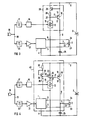
- Figures 1 to 5 show hearing aid circuits according to the invention as block diagrams with advantageous variants and designs of adjustable electronic limiting devices.
- the hearing aid circuit according to FIG. 1 comprises an output stage 1, which is connected via a receiver 2 to a battery 3 to form a circuit.
- the circuit is closed via lines 4 to 9 and transistor 10.
- the transistor 10 is a first controllable semiconductor - that is to say a controllable (adjustable) electronic component - and is used in this hearing aid circuit as an adjustable and electronic limiting device.
- the effect of the limiting device becomes ineffective, i.e. there is no limitation if the transistor 10 is operated as a current-carrying switch in the circuit.
- This can e.g. by a control connection 11 (basic connection) with an adjustable component, e.g.
- an actuator 12 (potentiometer or the like), which in turn is connected to a pole of the battery - in this exemplary embodiment to the negative pole.
- the resistance value of the actuator 12 is reduced at least to such an extent that a current is supplied to the transistor 10 via the control connection 11, which causes the transistor 10 to become conductive by overdriving. If there is sufficient overdrive, the transistor 10 is operated as a switch. The transistor 10 is thus conductive via its connections 13 and 14 (collector-emitter path).
- the transistor 10 After leaving its overdrive range, the transistor 10 is operated as a variable electronic resistor. Appropriate settings on the actuator 12 achieve different degrees of limitation of the electronic limiting device formed from the transistor 10.
- the transistor 10 can thus be placed as an adjustable and electronic limiting device in the immediate vicinity of the components of the circuit, as a result of which long lines which produce disruptive electrical fields are avoided.
- the maximum possible acoustic output level of the receiver 2 is practically no longer reduced by the simultaneously possible and inventive operating mode of the transistor 10 as a switch.
- the transistor 10 has a high current gain.
- the maximum current flow through the actuator 12 can remain particularly low.
- the actuator 12 can therefore be placed on an outer wall of a hearing aid even when using long lines.
- the actuator 12 can have a relatively high resistance value even if the limitation is ineffective.
- a programmable electronic actuator 15 can be used without any problems.
- the actuator 15 can e.g. can be programmed via a remote control receiving part 16, which receives remote control signals, e.g. pulse duration modulated ultrasound signals, via a high-pass filter 17 and a microphone 18 for evaluation and processing.
- the microphone 18 can simultaneously record voice signals and ambient noise, which are fed via a signal branch 19 to a low-pass filter 20 and a downstream amplifier 21, which is connected to the output stage 1, e.g. is connected via a volume control, not shown.
- the output stage 1 is designed as a push-pull output stage and the receiver 2 as a push-pull receiver.
- This push-pull receiver has a center connection 22 and two connections 23 and 24 connected to the push-pull output stage 1 via lines 5 and 6.
- the transistor 10 (first controllable semiconductor of the limiting device) is connected to the first connection 14 (emitter connection) via line 9 with the positive pole the battery 3 and with the second connection 13 (collector connection) via lines 7 and 8 to the center connection 22 of the push-pull receiver 2.
- a capacitor 25, which is connected to the center connection 22 of the receiver 2 and the negative pole of the battery 3, is used to suppress unwanted vibrations.
- the hearing aid circuit shown in FIG. 2 differs from the hearing aid circuit in accordance with FIG. 1 by a first resistor 26.
- This first resistor 26 is connected to the adjustable component, e.g. the programmable electronic actuator 15, connected to a first voltage divider, which is arranged between the two poles of the battery 3 for dividing the battery voltage.
- This first voltage divider has a voltage tap 27 which is connected to the control terminal 11 (base terminal) of the first controllable semiconductor (transistor 10).
- the resistance setting range is often restricted to higher resistance values.
- the setting range of the actuators 12 or 15 can be adapted to the transistor 10 provided as an adjustable and electronic limiting device.
- the first resistor in the first voltage divider is formed from a series circuit which includes resistor 28 with a fixed resistance and one second semiconductor, a transistor 29, which has a voltage-dependent, non-linear resistance value.
- the transistor 29 is a bipolar transistor connected as a diode and complementary to the first controllable semiconductor, the transistor 10, doped as an NPN type.
- the first voltage divider is formed from the actuator 12 or from the programmable electronic actuator 15 and a second controllable semiconductor having at least three connections, the transistor 30.
- the transistor 30 is a bipolar transistor and doped as a PNP type. Its collector-emitter path is connected in parallel with the base-emitter path of the transistor 10 via the two connections 31 and 32 corresponding to the first resistor 26 in FIG.
- the transistor 30 has a control connection 33 (base connection) which is connected to a voltage tap 34 with a second voltage divider.
- the second voltage divider is formed from a series connection of two resistors 35 and 36 with a fixed resistance and from a third semiconductor, a transistor 37.
- the transistor 37 has a voltage-dependent, non-linear resistance value, is connected as a diode, is designed as a bipolar transistor, is doped as an NPN type and is therefore doped complementarily to the first controllable semiconductor 10 and the second controllable semiconductor 30 in FIG. 4.
- the hearing device circuit arrangement according to FIG. 4 allows both earphones with low-impedance as well as with high-impedance impedance to be adapted to an adjustable electronic limiting circuit. If a programmable electronic actuator is selected as the actuator, with which only a certain number of resistance values can be programmed, as is typical in the type of construction, such an electronic actuator can also be adapted to the electronic limiting device and to the respective receiver impedance using the hearing device circuit shown in FIG. 4 .
- the hearing aid circuit has an adjustable electronic limiting device in which the first controllable semiconductor, the transistor 10, is arranged in the circuit as a switch bridging the adjustable limiting circuit.
- the adjustable limiting circuit comprises, as a programmable electronic resistor, the actuator 15, which can be programmed via a remote control, e.g. is set out in the description of Figure 1.
- the remote control receiving part 16 additionally switches via a line 38 and via the control connection 11 the transistor 10 for setting an ineffective limitation in the conductive region (switch operation), as a result of which the current in the circuit of the output stage 1 no longer flows via the electronic actuator 15.
- the transistor 10 is blocked (blocking mode), which is indicated by a corresponding switching signal, e.g. De-energization on line 38, from which remote control receiving part 16 is effected.
- the electronic limiting device can be designed entirely or partially as part of an integrated circuit, as symbolically indicated by a dashed boundary line 39 in FIG. 5 and in FIGS. 1 to 3.
- the limiting device can also be designed, in whole or in part, together with the output stage 1 as a common integrated circuit, as has been symbolically represented by a dashed boundary line 40 in FIG. 4.
- the electronic limiting device e.g. shown in Figure 1 can also be controlled (set) via a current or voltage source, e.g. can be programmable via remote control.
- a current or voltage source e.g. can be programmable via remote control.
- the adjustable component which is connected to the control connection 11 of the transistor 10, is designed as a current or voltage source.
- IC integrated circuit
- the electronic limiting device can be arranged elsewhere in the circuit of the output stage 1 of the hearing device circuit according to the invention. So it is e.g. possible to arrange an electronic limiting device in each line 5 and 6 according to FIG. 1.
- At least one semiconductor of the electronic limiting device can also be designed as a unipolar transistor - field effect transistor.
Landscapes
- Health & Medical Sciences (AREA)
- General Health & Medical Sciences (AREA)
- Neurosurgery (AREA)
- Otolaryngology (AREA)
- Physics & Mathematics (AREA)
- Engineering & Computer Science (AREA)
- Acoustics & Sound (AREA)
- Signal Processing (AREA)
- Amplifiers (AREA)
- Control Of Amplification And Gain Control (AREA)
- Tone Control, Compression And Expansion, Limiting Amplitude (AREA)
Priority Applications (4)
| Application Number | Priority Date | Filing Date | Title |
|---|---|---|---|
| EP90114273A EP0468072B1 (fr) | 1990-07-25 | 1990-07-25 | Aide à l'audition comportant un amplificateur de sortie avec circuit limiteur |
| DE59008542T DE59008542D1 (de) | 1990-07-25 | 1990-07-25 | Hörgeräteschaltung mit einer Endstufe mit einer Begrenzungseinrichtung. |
| AT90114273T ATE118928T1 (de) | 1990-07-25 | 1990-07-25 | Hörgeräteschaltung mit einer endstufe mit einer begrenzungseinrichtung. |
| US07/729,569 US5189704A (en) | 1990-07-25 | 1991-07-15 | Hearing aid circuit having an output stage with a limiting means |
Applications Claiming Priority (1)
| Application Number | Priority Date | Filing Date | Title |
|---|---|---|---|
| EP90114273A EP0468072B1 (fr) | 1990-07-25 | 1990-07-25 | Aide à l'audition comportant un amplificateur de sortie avec circuit limiteur |
Publications (2)
| Publication Number | Publication Date |
|---|---|
| EP0468072A1 true EP0468072A1 (fr) | 1992-01-29 |
| EP0468072B1 EP0468072B1 (fr) | 1995-02-22 |
Family
ID=8204258
Family Applications (1)
| Application Number | Title | Priority Date | Filing Date |
|---|---|---|---|
| EP90114273A Expired - Lifetime EP0468072B1 (fr) | 1990-07-25 | 1990-07-25 | Aide à l'audition comportant un amplificateur de sortie avec circuit limiteur |
Country Status (4)
| Country | Link |
|---|---|
| US (1) | US5189704A (fr) |
| EP (1) | EP0468072B1 (fr) |
| AT (1) | ATE118928T1 (fr) |
| DE (1) | DE59008542D1 (fr) |
Families Citing this family (24)
| Publication number | Priority date | Publication date | Assignee | Title |
|---|---|---|---|---|
| US8085959B2 (en) * | 1994-07-08 | 2011-12-27 | Brigham Young University | Hearing compensation system incorporating signal processing techniques |
| US5500902A (en) * | 1994-07-08 | 1996-03-19 | Stockham, Jr.; Thomas G. | Hearing aid device incorporating signal processing techniques |
| JP3727431B2 (ja) * | 1995-12-08 | 2005-12-14 | シャープ株式会社 | 送話器、それを用いた電話機 |
| US6760457B1 (en) | 2000-09-11 | 2004-07-06 | Micro Ear Technology, Inc. | Automatic telephone switch for hearing aid |
| US7248713B2 (en) * | 2000-09-11 | 2007-07-24 | Micro Bar Technology, Inc. | Integrated automatic telephone switch |
| US6934400B1 (en) * | 2000-11-03 | 2005-08-23 | Phonak Ag | Method for controlling the dynamic range of a hearing aid, and method to manufacture different hearing aids, and a hearing aid |
| EP1251714B2 (fr) * | 2001-04-12 | 2015-06-03 | Sound Design Technologies Ltd. | Système digital de prothèse auditive |
| US6633202B2 (en) | 2001-04-12 | 2003-10-14 | Gennum Corporation | Precision low jitter oscillator circuit |
| CA2382358C (fr) | 2001-04-18 | 2007-01-09 | Gennum Corporation | Detecteur numerique quasi quadratique |
| DK1251715T4 (da) * | 2001-04-18 | 2011-01-10 | Sound Design Technologies Ltd | Flerkanalshøreapparat med kommunikation mellem kanalerne |
| US20020191800A1 (en) * | 2001-04-19 | 2002-12-19 | Armstrong Stephen W. | In-situ transducer modeling in a digital hearing instrument |
| US7113589B2 (en) * | 2001-08-15 | 2006-09-26 | Gennum Corporation | Low-power reconfigurable hearing instrument |
| US7447325B2 (en) * | 2002-09-12 | 2008-11-04 | Micro Ear Technology, Inc. | System and method for selectively coupling hearing aids to electromagnetic signals |
| US7369671B2 (en) * | 2002-09-16 | 2008-05-06 | Starkey, Laboratories, Inc. | Switching structures for hearing aid |
| US8284970B2 (en) * | 2002-09-16 | 2012-10-09 | Starkey Laboratories Inc. | Switching structures for hearing aid |
| US8357103B2 (en) * | 2003-10-14 | 2013-01-22 | Suros Surgical Systems, Inc. | Vacuum assisted biopsy needle set |
| US20050281421A1 (en) * | 2004-06-22 | 2005-12-22 | Armstrong Stephen W | First person acoustic environment system and method |
| US8160261B2 (en) * | 2005-01-18 | 2012-04-17 | Sensaphonics, Inc. | Audio monitoring system |
| DK176789B1 (da) * | 2005-03-23 | 2009-08-31 | Gn Resound As | Et höreapparat med en strömbegrænser |
| US9774961B2 (en) | 2005-06-05 | 2017-09-26 | Starkey Laboratories, Inc. | Hearing assistance device ear-to-ear communication using an intermediate device |
| US8041066B2 (en) | 2007-01-03 | 2011-10-18 | Starkey Laboratories, Inc. | Wireless system for hearing communication devices providing wireless stereo reception modes |
| US8208642B2 (en) | 2006-07-10 | 2012-06-26 | Starkey Laboratories, Inc. | Method and apparatus for a binaural hearing assistance system using monaural audio signals |
| US9420385B2 (en) | 2009-12-21 | 2016-08-16 | Starkey Laboratories, Inc. | Low power intermittent messaging for hearing assistance devices |
| US10003379B2 (en) | 2014-05-06 | 2018-06-19 | Starkey Laboratories, Inc. | Wireless communication with probing bandwidth |
Citations (4)
| Publication number | Priority date | Publication date | Assignee | Title |
|---|---|---|---|---|
| FR2527925A1 (fr) * | 1982-06-07 | 1983-12-09 | Utzmann Rene | Prothese auditive a signal de sortie controle |
| GB2166015A (en) * | 1984-10-05 | 1986-04-23 | Ross Marks Limited | Overload preventing circuit for headphones |
| EP0237203A2 (fr) * | 1986-03-12 | 1987-09-16 | Beltone Electronics Corporation | Circuit pour prothèse auditive |
| WO1989008353A1 (fr) * | 1988-02-23 | 1989-09-08 | Resound Corporation | Systeme ameliore de compression programmable a bandes multiples |
Family Cites Families (6)
| Publication number | Priority date | Publication date | Assignee | Title |
|---|---|---|---|---|
| US3867576A (en) * | 1973-12-14 | 1975-02-18 | Northern Electric Co | Telephone transmitter circuit |
| DE2658301C2 (de) * | 1976-12-22 | 1978-12-07 | Siemens Ag, 1000 Berlin Und 8000 Muenchen | Hörgerät |
| ATE14361T1 (de) * | 1981-10-20 | 1985-08-15 | Craigwell Ind Ltd | Hoerhilfegeraete. |
| US4543453A (en) * | 1983-03-30 | 1985-09-24 | Beltone Electronics Corporation | Electronic hearing aid control circuit |
| JPS6196807A (ja) * | 1984-10-17 | 1986-05-15 | Rohm Co Ltd | 自動レベル制御増幅回路 |
| US5025214A (en) * | 1990-06-25 | 1991-06-18 | The Warner & Swasey Company | Circuit and process for converting a half bridge transducer output signal to an LVDT transducer output signal |
-
1990
- 1990-07-25 AT AT90114273T patent/ATE118928T1/de not_active IP Right Cessation
- 1990-07-25 EP EP90114273A patent/EP0468072B1/fr not_active Expired - Lifetime
- 1990-07-25 DE DE59008542T patent/DE59008542D1/de not_active Expired - Fee Related
-
1991
- 1991-07-15 US US07/729,569 patent/US5189704A/en not_active Expired - Fee Related
Patent Citations (4)
| Publication number | Priority date | Publication date | Assignee | Title |
|---|---|---|---|---|
| FR2527925A1 (fr) * | 1982-06-07 | 1983-12-09 | Utzmann Rene | Prothese auditive a signal de sortie controle |
| GB2166015A (en) * | 1984-10-05 | 1986-04-23 | Ross Marks Limited | Overload preventing circuit for headphones |
| EP0237203A2 (fr) * | 1986-03-12 | 1987-09-16 | Beltone Electronics Corporation | Circuit pour prothèse auditive |
| WO1989008353A1 (fr) * | 1988-02-23 | 1989-09-08 | Resound Corporation | Systeme ameliore de compression programmable a bandes multiples |
Also Published As
| Publication number | Publication date |
|---|---|
| DE59008542D1 (de) | 1995-03-30 |
| ATE118928T1 (de) | 1995-03-15 |
| US5189704A (en) | 1993-02-23 |
| EP0468072B1 (fr) | 1995-02-22 |
Similar Documents
| Publication | Publication Date | Title |
|---|---|---|
| EP0468072B1 (fr) | Aide à l'audition comportant un amplificateur de sortie avec circuit limiteur | |
| DE3435728C2 (de) | Transistorisierte Verstärker- und Mischer-Eingangsstufe | |
| DE2824468C2 (de) | Telefonverstärkerschaltung | |
| DE3204217A1 (de) | Schaltung zur elektronischen verstaerkungsstellung | |
| DE2718491C2 (de) | Schaltungsanordnung zur Verstärkung der Signale eines elektromagnetischen Wandlers und zur Vorspannungserzeugung für den Wandler | |
| DE2213484C3 (de) | Hochfrequenter Breitbandverstärker | |
| DE3854006T2 (de) | Generator von periodischen Signalen, insbesondere für Schaltnetzteile. | |
| DE2707870C2 (de) | Schaltungsanordnung zur Verstärkungssteuerung | |
| EP0307641A1 (fr) | Circuit pour supprimer des signaux parasites | |
| DE3036417A1 (de) | Eingangsschaltung fuer hoerapparateverstaerker | |
| EP0446195B1 (fr) | Circuit monocanal pour aide auditive | |
| DE2424335A1 (de) | Leitungsanpassungsschaltung fuer einen mit einem tongenerator ausgeruesteten tondrucktastenwahlfernsprecher | |
| DE2755827A1 (de) | Schaltungsanordnung mit einem durch eine steuergleichspannung veraenderbaren frequenzgang | |
| DE69108424T2 (de) | Spannungsgesteuerter Widerstand. | |
| DE3854047T2 (de) | Asymetrischer verstärker mit zwei eingängen. | |
| CH622389A5 (fr) | ||
| DE2657589C2 (de) | Dämpfungsfreier elektronischer Schalter | |
| DE2711520C3 (de) | Belastungsschaltung für eine Signalquelle | |
| DE1274754B (de) | Elektrisches Filter | |
| DE2658278C3 (de) | Pufferverstärker für elektrische Signale | |
| DE19637292B4 (de) | Verstärkerschaltung, insbesondere zur Verstärkung von Audiosignalen und Audioverstärker | |
| DE1200881C2 (de) | Regelbarer gleichstromgekoppelter Verstaerker | |
| DE3852310T2 (de) | Ausgangsverstärker. | |
| DE3513197A1 (de) | Aktive tonblende fuer hoergeraete | |
| DE2637500C2 (de) | Leistungsverstärker zur Verstärkung elektrischer Spannungen |
Legal Events
| Date | Code | Title | Description |
|---|---|---|---|
| PUAI | Public reference made under article 153(3) epc to a published international application that has entered the european phase |
Free format text: ORIGINAL CODE: 0009012 |
|
| 17P | Request for examination filed |
Effective date: 19901205 |
|
| AK | Designated contracting states |
Kind code of ref document: A1 Designated state(s): AT CH DE DK FR GB IT LI NL |
|
| RBV | Designated contracting states (corrected) |
Designated state(s): AT CH DE DK FR GB LI |
|
| RAP1 | Party data changed (applicant data changed or rights of an application transferred) |
Owner name: SIEMENS AUDIOLOGISCHE TECHNIK GMBH |
|
| 17Q | First examination report despatched |
Effective date: 19940725 |
|
| GRAA | (expected) grant |
Free format text: ORIGINAL CODE: 0009210 |
|
| AK | Designated contracting states |
Kind code of ref document: B1 Designated state(s): AT CH DE DK FR GB LI |
|
| PG25 | Lapsed in a contracting state [announced via postgrant information from national office to epo] |
Ref country code: GB Effective date: 19950222 Ref country code: FR Effective date: 19950222 Ref country code: DK Effective date: 19950222 |
|
| REF | Corresponds to: |
Ref document number: 118928 Country of ref document: AT Date of ref document: 19950315 Kind code of ref document: T |
|
| REF | Corresponds to: |
Ref document number: 59008542 Country of ref document: DE Date of ref document: 19950330 |
|
| EN | Fr: translation not filed | ||
| PG25 | Lapsed in a contracting state [announced via postgrant information from national office to epo] |
Ref country code: AT Effective date: 19950725 |
|
| PG25 | Lapsed in a contracting state [announced via postgrant information from national office to epo] |
Ref country code: LI Effective date: 19950731 Ref country code: CH Effective date: 19950731 |
|
| GBV | Gb: ep patent (uk) treated as always having been void in accordance with gb section 77(7)/1977 [no translation filed] |
Effective date: 19950222 |
|
| PLBE | No opposition filed within time limit |
Free format text: ORIGINAL CODE: 0009261 |
|
| STAA | Information on the status of an ep patent application or granted ep patent |
Free format text: STATUS: NO OPPOSITION FILED WITHIN TIME LIMIT |
|
| 26N | No opposition filed | ||
| REG | Reference to a national code |
Ref country code: CH Ref legal event code: PL |
|
| PG25 | Lapsed in a contracting state [announced via postgrant information from national office to epo] |
Ref country code: DE Effective date: 19960402 |