EP0468096B1 - Gehäuse für ein elektrisches Bauelement, insbesondere ein Relais - Google Patents
Gehäuse für ein elektrisches Bauelement, insbesondere ein Relais Download PDFInfo
- Publication number
- EP0468096B1 EP0468096B1 EP90124633A EP90124633A EP0468096B1 EP 0468096 B1 EP0468096 B1 EP 0468096B1 EP 90124633 A EP90124633 A EP 90124633A EP 90124633 A EP90124633 A EP 90124633A EP 0468096 B1 EP0468096 B1 EP 0468096B1
- Authority
- EP
- European Patent Office
- Prior art keywords
- distribution
- channel
- channels
- edge
- housing
- Prior art date
- Legal status (The legal status is an assumption and is not a legal conclusion. Google has not performed a legal analysis and makes no representation as to the accuracy of the status listed.)
- Expired - Lifetime
Links
- 238000007789 sealing Methods 0.000 claims abstract description 17
- 238000005266 casting Methods 0.000 claims description 6
- 230000007423 decrease Effects 0.000 claims description 3
- 244000182067 Fraxinus ornus Species 0.000 claims 1
- 230000000694 effects Effects 0.000 abstract description 3
- 150000001875 compounds Chemical class 0.000 description 13
- 238000004382 potting Methods 0.000 description 7
- 230000002349 favourable effect Effects 0.000 description 2
- 230000035515 penetration Effects 0.000 description 1
- 230000002093 peripheral effect Effects 0.000 description 1
- 239000011347 resin Substances 0.000 description 1
- 229920005989 resin Polymers 0.000 description 1
- 238000005476 soldering Methods 0.000 description 1
- 238000009423 ventilation Methods 0.000 description 1
- 238000005406 washing Methods 0.000 description 1
Images

Classifications
-
- H—ELECTRICITY
- H01—ELECTRIC ELEMENTS
- H01H—ELECTRIC SWITCHES; RELAYS; SELECTORS; EMERGENCY PROTECTIVE DEVICES
- H01H50/00—Details of electromagnetic relays
- H01H50/02—Bases; Casings; Covers
- H01H50/023—Details concerning sealing, e.g. sealing casing with resin
Definitions
- the invention relates to a housing for an electrical component, in particular a relay, with a housing wall which closes off a hollow interior and which has sealing points, such as openings and gaps in the region of connecting pins and / or on their edge, according to the preamble of patent claim; see DE-A 28 51 329.
- the object of the invention is to provide a housing of the type mentioned in the introduction, in which a particularly rapid and reliable distribution of a sealing compound from one or more filling points to the sealing points is ensured by an improved surface structure of the relevant housing wall.
- such a housing has the features according to patent claim 1 to achieve the stated object.
- elements of capillary systems which are known per se are combined by additionally forming a distribution rib in the distribution channels, which results in a system of double channels.
- a distribution rib in the distribution channels, which results in a system of double channels.
- the distribution channels open at approximately equal distances into a circumferential edge channel, the width of which is expediently less than the width of the distribution channels.
- the distribution ribs of the distribution channels extend into the edge channel up to its outer wall. This outer wall is usually formed by the edge of a housing cap which is placed on a base part or a base or the like and forms an edge gap to be sealed with the latter.
- special end channels can be provided which branch off from a distribution channel or from the edge channel. It is advantageous if the width of the capillary sections decreases from the respective filling container via the distribution channels to the edge channel or to the end channels.
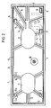
- the base body 1 shown in FIGS. 1 and 2 for a relay housing is largely flat and is provided on its upper side with projections 2 for fastening a relay system (not shown further).
- the base body 1 has approximately round openings 3 for wire-shaped coil connection pins and rectangular openings 4, 5 and 6 for differently designed contact connection elements. After inserting the aforementioned pins, not shown, into the openings 3 to 6 and after the relay has been fully assembled these openings 3 to 6 are sealed with potting compound.
- an edge gap 8 is to be sealed, which is formed all around between the base body 1 and a housing cap 7 from above, as shown in FIG.
- a ventilation hole 10 formed in a protruding pin 9 should only be sealed in a manner known per se after the casting compound has hardened.
- Distribution channels 13 branch off from these filling containers in the direction of the openings 3 or 4, 5 and 6 and the edge gaps 8.
- Each of these distribution channels 13 is divided in the middle in the longitudinal direction by a distribution rib 14 into two sub-channels 13a and 13b, a sharp inner edge being formed in each case between the channel bottom and the side walls of the distribution channels or the distribution ribs.
- the depth of the distribution channels corresponds approximately to the width of the sub-channels and, in an expedient embodiment, is approximately between 0.3 and 0.4 mm. Depending on the viscosity of the potting compound, other dimensions can also be favorable.
- a peripheral edge channel 15 is also formed, the width of which is smaller than that of the distribution channels, if possible also less than that of the sub-channels.
- a particularly favorable embodiment has an edge channel with a width between 0.2 and 0.3 mm.
- the distribution channels are arranged so that they open into the edge channel at approximately equal intervals.
- the distribution ribs are up to the opening 3 and from this further to the edge channel.
- the distribution ribs 14 still extend over the width of the respective edge channel 15 to the outside thereof and thus abut the housing cap 7. To this The potting compound is guided very well into the marginal gaps 8.
- small end channels 16, 17 and 18 with a particularly small width and thus particularly good capillary action are additionally provided, which branch off either from one of the distribution channels 13 or from the edge channel 8.
- the gradual reduction in the channel cross section with increasing distance from a filling container ensures that the potting compound is sucked out quickly and completely from the filling container 11 or 12 and transported to the most distant sealing points.
- FIG. 3 shows a somewhat modified embodiment of a housing element in the form of a base plate 21, which together with a cap (not shown) also forms a housing for a relay or a similar component.
- a central filling container 22 is formed, from which distribution channels 23 with distribution ribs 24 lead to the various housing openings 25 and 26 with a round or rectangular shape and to an edge channel 28.
- the distribution ribs 24 are each led into the openings 25 and 26 with vertical sections 27, the side walls 29 being designed to be somewhat beveled in this area. This results in a capillary action between the rib sections 27 and the respective breakthrough walls 29 up to the openings.
Landscapes
- Physics & Mathematics (AREA)
- Electromagnetism (AREA)
- Casings For Electric Apparatus (AREA)
- Packages (AREA)
- Switch Cases, Indication, And Locking (AREA)
- Mounting Components In General For Electric Apparatus (AREA)
- Connections Arranged To Contact A Plurality Of Conductors (AREA)
- Connection Or Junction Boxes (AREA)
Applications Claiming Priority (2)
| Application Number | Priority Date | Filing Date | Title |
|---|---|---|---|
| DE9011111U | 1990-07-27 | ||
| DE9011111U DE9011111U1 (de) | 1990-07-27 | 1990-07-27 | Gehäuse für ein elektrisches Bauelement, insbesondere ein Relais |
Publications (2)
| Publication Number | Publication Date |
|---|---|
| EP0468096A1 EP0468096A1 (de) | 1992-01-29 |
| EP0468096B1 true EP0468096B1 (de) | 1995-02-15 |
Family
ID=6855999
Family Applications (1)
| Application Number | Title | Priority Date | Filing Date |
|---|---|---|---|
| EP90124633A Expired - Lifetime EP0468096B1 (de) | 1990-07-27 | 1990-12-18 | Gehäuse für ein elektrisches Bauelement, insbesondere ein Relais |
Country Status (5)
| Country | Link |
|---|---|
| US (1) | US5194694A (pt) |
| EP (1) | EP0468096B1 (pt) |
| AT (1) | ATE118645T1 (pt) |
| DE (2) | DE9011111U1 (pt) |
| PT (2) | PT98443A (pt) |
Families Citing this family (9)
| Publication number | Priority date | Publication date | Assignee | Title |
|---|---|---|---|---|
| GB9118599D0 (en) * | 1991-08-30 | 1991-10-16 | Moulded Circuits Ltd | Manufacturing method for electrical circuit board |
| US5497136A (en) * | 1992-11-30 | 1996-03-05 | Dana Corporation | Locating ring for encapsulating a coil |
| GB2290170B (en) * | 1993-02-03 | 1996-08-14 | A Dec Inc | Control panel with sealed switch keypad |
| DE4337505C1 (de) * | 1993-11-03 | 1995-03-30 | Siemens Ag | Elektromechanisches Bauelement, insbesondere Relais, mit dichtem Gehäuse |
| US5462622A (en) * | 1994-06-09 | 1995-10-31 | Illinois Tool Works Inc. | Molding an electrical element within a premold element and an overmold element to provide a one-piece component |
| DE19531046A1 (de) * | 1995-08-23 | 1997-02-27 | Siemens Ag | Elektromagnetisches Relais und Verfahren zu dessen Herstellung |
| EP1720389B1 (en) * | 2005-04-25 | 2019-07-03 | Brother Kogyo Kabushiki Kaisha | Method for forming pattern and a wired board |
| DE102007025338B4 (de) * | 2007-05-31 | 2015-02-05 | Tyco Electronics Amp Gmbh | Verfahren zum Abdichten eines Gehäuses und elektrische Komponente |
| JP7122674B2 (ja) * | 2018-09-27 | 2022-08-22 | パナソニックIpマネジメント株式会社 | 電気機器及び電磁継電器 |
Family Cites Families (5)
| Publication number | Priority date | Publication date | Assignee | Title |
|---|---|---|---|---|
| CH625381A5 (pt) * | 1977-12-02 | 1981-09-15 | Standard Telephon & Radio Ag | |
| DE7821508U1 (de) * | 1978-07-18 | 1978-10-26 | Siemens Ag, 1000 Berlin Und 8000 Muenchen | Elektromechanisches Bauelement, insbesondere Relais |
| DE3026371C2 (de) * | 1980-07-11 | 1990-07-12 | Siemens AG, 1000 Berlin und 8000 München | Gehäuse für ein elektrisches Bauelement und Verfahren zu dessen Abdichtung |
| US4810831A (en) * | 1986-09-30 | 1989-03-07 | Siemens-Albis Aktiengesellschaft | Housing for an electrical component, and method for sealing same |
| DE3706100A1 (de) * | 1987-02-25 | 1988-09-08 | Siemens Ag | Elektromechanisches bauelement, insbesondere elektromagnetisches relais |
-
1990
- 1990-07-27 DE DE9011111U patent/DE9011111U1/de not_active Expired - Lifetime
- 1990-12-18 DE DE59008487T patent/DE59008487D1/de not_active Expired - Lifetime
- 1990-12-18 AT AT90124633T patent/ATE118645T1/de not_active IP Right Cessation
- 1990-12-18 EP EP90124633A patent/EP0468096B1/de not_active Expired - Lifetime
-
1991
- 1991-06-10 US US07/712,467 patent/US5194694A/en not_active Expired - Lifetime
- 1991-07-25 PT PT98443A patent/PT98443A/pt active IP Right Grant
-
1993
- 1993-06-25 PT PT8823U patent/PT8823U/pt not_active IP Right Cessation
Also Published As
| Publication number | Publication date |
|---|---|
| EP0468096A1 (de) | 1992-01-29 |
| PT98443A (pt) | 1993-09-30 |
| ATE118645T1 (de) | 1995-03-15 |
| DE9011111U1 (de) | 1991-11-21 |
| PT8823T (pt) | 1993-12-31 |
| PT8823U (pt) | 1997-09-30 |
| US5194694A (en) | 1993-03-16 |
| DE59008487D1 (de) | 1995-03-23 |
Similar Documents
| Publication | Publication Date | Title |
|---|---|---|
| DE3831573C2 (pt) | ||
| DE19838008B4 (de) | Elektrische Anschlußklemme, insbesondere für den Einsatz auf Leiterplatten | |
| EP0113809A2 (de) | Elektrischer Steckverbinder mit einer Verriegelungseinrichtung für ein in einer Gehäusekammer steckendes, elektrisches Kontaktelement | |
| DE3435822C2 (de) | Klinkensteckbuchse mit eingebetteten Kontaktelementen | |
| DE3590369C2 (pt) | ||
| DE3026371C2 (de) | Gehäuse für ein elektrisches Bauelement und Verfahren zu dessen Abdichtung | |
| EP3490075A1 (de) | Set aus steckverbinder und halteelement sowie steckverbinder und halteelement hierzu | |
| DE20319849U1 (de) | Steckverbindervorrichtung für mehradrige Flachbandkabel | |
| EP0982978B1 (de) | Gehäuse, insbesondere Schlossgehäuse mit elektrischen Anschlusseinrichtungen | |
| EP0468096A1 (de) | Gehäuse für ein elektrisches Bauelement, insbesondere ein Relais | |
| DE10349487A1 (de) | Wasserdichter Abdeckaufbau für eine elektrische Verteilerdose | |
| DE2213146B2 (de) | Relais | |
| DE8530054U1 (de) | Elektrischer Stecker | |
| DE19505123B4 (de) | Gehäuse zur Aufnahme zumindest einer elektrischen Schaltungsplatte eines elektrischen Schalt- oder Steuergeräts | |
| EP0138068A2 (de) | Gehäuse für ein elektromechanisches Bauelement, insbesondere Relais | |
| DE4338562C2 (de) | Elektrisches Verbinderbauteil mit gesicherter Abdichtung | |
| EP0262622B1 (de) | Gehäuse für ein elektrisches Bauelement, insbesondere ein Relais, und Verfahren zur Abdichtung eines solchen | |
| EP0703641A2 (de) | Elektrisches Steckverbindungsteil | |
| DE2448349C2 (de) | Verbinderanordnung mit einem mit einer gedruckten Schaltungsplatte verbundenen Verbinder | |
| DE69903231T2 (de) | Kontaktteil für Verbindungsbuchse und Verbinder mit einem solchen Kontaktteil | |
| WO2020126881A1 (de) | Halterahmen für enen steckverbinder | |
| DE2148895A1 (de) | Kontaktstreifen und Giessform zur Montage von Halbleiterbauelementen | |
| DE4102349C2 (de) | Kontrollgerät zur Stromkreisüberwachung | |
| DE8420661U1 (de) | Elektrischer Hilfsanschluss | |
| EP0454669B1 (de) | Gehaüse für ein elektromechanisches bauelement, insbesondere für ein relais |
Legal Events
| Date | Code | Title | Description |
|---|---|---|---|
| PUAI | Public reference made under article 153(3) epc to a published international application that has entered the european phase |
Free format text: ORIGINAL CODE: 0009012 |
|
| 17P | Request for examination filed |
Effective date: 19901218 |
|
| AK | Designated contracting states |
Kind code of ref document: A1 Designated state(s): AT CH DE FR GB IT LI |
|
| 17Q | First examination report despatched |
Effective date: 19940124 |
|
| GRAA | (expected) grant |
Free format text: ORIGINAL CODE: 0009210 |
|
| AK | Designated contracting states |
Kind code of ref document: B1 Designated state(s): AT CH DE FR GB IT LI |
|
| REF | Corresponds to: |
Ref document number: 118645 Country of ref document: AT Date of ref document: 19950315 Kind code of ref document: T |
|
| REF | Corresponds to: |
Ref document number: 59008487 Country of ref document: DE Date of ref document: 19950323 |
|
| ITF | It: translation for a ep patent filed | ||
| GBT | Gb: translation of ep patent filed (gb section 77(6)(a)/1977) |
Effective date: 19950427 |
|
| ET | Fr: translation filed | ||
| PLBE | No opposition filed within time limit |
Free format text: ORIGINAL CODE: 0009261 |
|
| STAA | Information on the status of an ep patent application or granted ep patent |
Free format text: STATUS: NO OPPOSITION FILED WITHIN TIME LIMIT |
|
| 26N | No opposition filed | ||
| PGFP | Annual fee paid to national office [announced via postgrant information from national office to epo] |
Ref country code: CH Payment date: 19960320 Year of fee payment: 6 |
|
| PGFP | Annual fee paid to national office [announced via postgrant information from national office to epo] |
Ref country code: GB Payment date: 19961118 Year of fee payment: 7 |
|
| PGFP | Annual fee paid to national office [announced via postgrant information from national office to epo] |
Ref country code: AT Payment date: 19961127 Year of fee payment: 7 |
|
| PGFP | Annual fee paid to national office [announced via postgrant information from national office to epo] |
Ref country code: FR Payment date: 19961223 Year of fee payment: 7 |
|
| PG25 | Lapsed in a contracting state [announced via postgrant information from national office to epo] |
Ref country code: LI Effective date: 19961231 Ref country code: CH Effective date: 19961231 |
|
| REG | Reference to a national code |
Ref country code: CH Ref legal event code: PL |
|
| PG25 | Lapsed in a contracting state [announced via postgrant information from national office to epo] |
Ref country code: GB Free format text: LAPSE BECAUSE OF NON-PAYMENT OF DUE FEES Effective date: 19971218 Ref country code: AT Free format text: LAPSE BECAUSE OF NON-PAYMENT OF DUE FEES Effective date: 19971218 |
|
| PG25 | Lapsed in a contracting state [announced via postgrant information from national office to epo] |
Ref country code: FR Free format text: THE PATENT HAS BEEN ANNULLED BY A DECISION OF A NATIONAL AUTHORITY Effective date: 19971231 |
|
| GBPC | Gb: european patent ceased through non-payment of renewal fee |
Effective date: 19971218 |
|
| REG | Reference to a national code |
Ref country code: FR Ref legal event code: ST |
|
| PG25 | Lapsed in a contracting state [announced via postgrant information from national office to epo] |
Ref country code: IT Free format text: LAPSE BECAUSE OF NON-PAYMENT OF DUE FEES;WARNING: LAPSES OF ITALIAN PATENTS WITH EFFECTIVE DATE BEFORE 2007 MAY HAVE OCCURRED AT ANY TIME BEFORE 2007. THE CORRECT EFFECTIVE DATE MAY BE DIFFERENT FROM THE ONE RECORDED. Effective date: 20051218 |
|
| PGFP | Annual fee paid to national office [announced via postgrant information from national office to epo] |
Ref country code: DE Payment date: 20091230 Year of fee payment: 20 |
|
| PG25 | Lapsed in a contracting state [announced via postgrant information from national office to epo] |
Ref country code: DE Free format text: LAPSE BECAUSE OF EXPIRATION OF PROTECTION Effective date: 20101218 |