EP0468108A1 - Träger aus Stahl für Betonschalungen - Google Patents
Träger aus Stahl für Betonschalungen Download PDFInfo
- Publication number
- EP0468108A1 EP0468108A1 EP90308048A EP90308048A EP0468108A1 EP 0468108 A1 EP0468108 A1 EP 0468108A1 EP 90308048 A EP90308048 A EP 90308048A EP 90308048 A EP90308048 A EP 90308048A EP 0468108 A1 EP0468108 A1 EP 0468108A1
- Authority
- EP
- European Patent Office
- Prior art keywords
- soldier
- flange
- openings
- beams
- opening
- Prior art date
- Legal status (The legal status is an assumption and is not a legal conclusion. Google has not performed a legal analysis and makes no representation as to the accuracy of the status listed.)
- Withdrawn
Links
- 229910000831 Steel Inorganic materials 0.000 title claims abstract description 18
- 239000010959 steel Substances 0.000 title claims abstract description 18
- 238000009415 formwork Methods 0.000 title claims abstract description 7
- 125000006850 spacer group Chemical group 0.000 claims description 15
- 230000000712 assembly Effects 0.000 abstract description 5
- 238000000429 assembly Methods 0.000 abstract description 5
- 238000005452 bending Methods 0.000 abstract description 3
- 230000000694 effects Effects 0.000 description 5
- 238000006243 chemical reaction Methods 0.000 description 2
- 238000005058 metal casting Methods 0.000 description 2
- 230000002093 peripheral effect Effects 0.000 description 2
- 230000006835 compression Effects 0.000 description 1
- 238000007906 compression Methods 0.000 description 1
- 239000000835 fiber Substances 0.000 description 1
- 230000004048 modification Effects 0.000 description 1
- 238000012986 modification Methods 0.000 description 1
- 230000003019 stabilising effect Effects 0.000 description 1
Images


Classifications
-
- E—FIXED CONSTRUCTIONS
- E04—BUILDING
- E04G—SCAFFOLDING; FORMS; SHUTTERING; BUILDING IMPLEMENTS OR AIDS, OR THEIR USE; HANDLING BUILDING MATERIALS ON THE SITE; REPAIRING, BREAKING-UP OR OTHER WORK ON EXISTING BUILDINGS
- E04G25/00—Shores or struts; Chocks
- E04G25/02—Shores or struts; Chocks non-telescopic
-
- E—FIXED CONSTRUCTIONS
- E04—BUILDING
- E04G—SCAFFOLDING; FORMS; SHUTTERING; BUILDING IMPLEMENTS OR AIDS, OR THEIR USE; HANDLING BUILDING MATERIALS ON THE SITE; REPAIRING, BREAKING-UP OR OTHER WORK ON EXISTING BUILDINGS
- E04G17/00—Connecting or other auxiliary members for forms, falsework structures, or shutterings
- E04G17/14—Bracing or strutting arrangements for formwalls; Devices for aligning forms
Definitions
- This invention relates to structural members, particularly steel structural members known as “soldiers” and used for supporting concrete formwork.
- British patent specifications nos. 1 551 154 and 2 145 145 disclose structural members called soldiers for concrete formwork. These disclosed soldiers are of a kind which comprise a pair of elongate steel beams, which may be of channel section, connected back to back and parallel with one another. Each beam has a web which, in order to minimise weight, has openings spaced at regular intervals along its length. To increase the stability of these webs the openings have peripheral lips otherwise known, and hereinafter referred to, as flanges. Further, the flanges of the respective webs may be flared as appropriate in mutually opposite directions.
- the present invention has for one object the provision of a structural member which is a modification of the soldier described and illustrated in British patent specification no. 2 145 145, enabling use of a connector assembly which, in combination with the structural member, provides excellent mechanical properties.
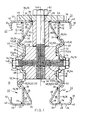
- the steel soldier 10 comprises two mutually spaced apart and mutually parallel beams 12, 12 which are symmetrically disposed relative to first and second mutually perpendicular planes of symmetry 14A, 14B. These planes of symmetry 14A, 14B both extend along the length of the structural member 10, which is symmetrical about both planes 14A, 14B.
- the two beams 12, 12 are of the same length and are co-extensive, being connected to each other at their ends by two rectangular rigid tie plates 13, 13 (see Fig. 8) and, intermediate their ends, by one or more rigid diaphragms 15, welded to the two beams 12, 12.
- Two beams 12, 12 have two respective webs 16, 16 in respective planes parallel to the first plane of symmetry 14A, which is disposed equidistantly between the two webs 16, 16.
- Each beam 12 also has a respective top and bottom chord portions 22, 22.
- Each chord 22 is formed respectively by inner and outer flange portions 24, 26, an oblique portion 28 and an edge-reinforcing portion 30.
- the inner and outer flange elements 24, 26 are perpendicular to the web 16 and extend from the outer edge 32 of web 16 respectively towards and away from the first plane of symmetry 14A.
- the oblique element 28 adjoins the web 16 at 31 and the inner flange portion 24 at 36 to form a closed hollow section 38, which extends continuously along the steel soldier 10 for providing torsional stability.
- the edge-reinforcing portion 30 is connected to an edge 40, remote from web 16, of the outer flange element 26 for stabilising the outer flange portion 26.
- Each beam 12 is made from three pieces of steel 42, 44, 45, welded together.
- Piece 42 forms the web 16, and piece 44 and 45 form the top and bottom chord portions, respectively.
- Piece 42 is welded to piece 44 at 31 and 32, and welded to piece 45 at 33 and 34.
- Pieces 44 and 45 are curved at 36 (where the oblique portion 28 adjoins the inner flange portion 24) and at edge 40 (where the edge-reinforcing portion 30 is connected to the outer flange portion 26).
- top and bottom chords portions 22, 22 are spaced apart by, and connected to, the web 16.
- each beam have a series of mutually opposite openings 46 along their lengths (see Fig. 8), the openings 46 each being elliptical (possibly circular, considered as a special form of elliptical).
- the web 16 Around a portion of each opening 46, the web 16 has a flange 48 (not shown in Fig. 14).
- Each flange 48 must cover enough of the periphery of corresponding opening 46 so as to be capable of supporting clamping disc 52.
- flange 48 has a U-shaped profile in cross-section, wherein the open end of the flanges 48 of the respective webs 16 may face each other or opposite directions.
- the minor axis or alternatively the major axis of the ellipse should be central of the web 16, extending in the longitudinal direction of the beam 12.
- the dimensions of the openings are chosen empirically, according to the required strength and lightness of the steel soldier 10 and the function required of the steel soldier 10 in use.
- the openings 46 might not even be truly elliptical, depending on other requirements.
- One or more connector assemblies 51 may be connected to the steel soldier 10 at a respective pair of the mutually opposite openings 46.
- Each connector assembly 51 comprises a pair of clamping discs 52, 52 (Figs. 2-4), a spacer unit 54 (Figs. 5-7) and two bolts 56, 56 (Fig. 1).
- Each clamping disc 52 (Figs. 1-4) is a metal casting and comprises a spigot 58 which fits within the respective hole 46 and a dished contour flange 60 which embraces the flange 48 as shown in Fig. 1, engaging both the radially inner flange portion 53 and the radially outer flange portion 50.
- the spigot 58 and contour flange 60 in combination engage the whole of the radially inner flange portion 53 (Fig. 1) and a substantial part of the radially outer flange portion 50.
- the spacer unit 54 (Figs. 5-7) is a metal casting which fits between the two clamping disc 52, 52.
- the spacer unit 54 is formed with two projections 62, 62 which engage in correspondingly shaped recesses 55 in the clamping discs 52, 52. Whilst faces 64, 64, of the projections 62, 62 are spaced apart from corresponding faces of the clamping disc recesses 55, the sides 66, 66 of projections 62, 62 are in close contact with the corresponding surfaces of the clamping disc recesses 55. Faces 68, 68 of the spacer unit 54, around the projections 62, 62 are in close contact with corresponding faces 57, 57 of the clamping discs 52, 52 around the recesses 55.
- the bolts 56, 56 extend through the clamping discs 52, 52 and part way into the spacer unit 54. More particularly, heads 70,70 of the bolts 56, 56 engage the outsides (remote from the first plane of symmetry 14A) of central bosses 63, 63 of the clamping discs 52, 52, whilst screw-threaded shanks 74, 74 of bolts 56, 56 are threaded into a threaded through-hole 76 in spacer unit 54. The bolts 56, 56 are tightened so that the clamping discs 52, 52 are clamped tightly against the spacer unit 54 (via faces 68, 68) and against the flanges 48, 48 of the webs 16, 16.
- the spacer unit 54 has a further threaded through-hole 78 (see Figs. 5-7), the axis of which is perpendicular to the longitudinal direction of the soldier 10 and lies in the first plane of symmetry 14A.
- the through-hole 78 is threadedly engaged by a bolt 80 which extends into it .
- a head 82 on one end of the bolt 80 abuts a flange 84 of a fixed end unit 86.
- the fixed end unit 86 also comprises a sleeve 87, to which the flange 84 is welded at 85, the bolt 80 extending through both the flange 84 and the sleeve 87.
- the flange 84 abuts the two adjacent top chord portions 22, 22 of soldier 10.
- contour flanges 60 of clamping discs 52 bear on radially outer flange portions 50 at 96, sharing load distribution with the clamping disc spigots 58.
- Figs 8 and 9 on the one hand and Figs 10 and 11 on the other hand show the effect on the steel soldier 10 of a load respectively without, and with, the connector assembly 51.
- a rod 80A is loaded in the direction of arrow 88 and reaction is applied laterally to steel soldier 10 along its length.
- the opening 46A deforms as shown in Fig. 8, with excessive stress in regions 108 of web 16, between opening 46A and adjacent openings 46.
- Figs. 8 to 11 show a different fixed end unit 110 on rod 80 from fixed end unit 86 of Fig. 1.
- Figs. 12 and 13 illustrate the different effects of an applied load on the flange around the opening in the web of a soldier of the present invention (Fig. 12), on the one hand, and British patent specification no. 2 145 145 (Fig. 13), on the other hand ("UKPS 2 145 145").
- the openings OP in the web portions have been formed at their peripheries with lips of flanges FL which have a simple arcuate profile, whereas in accordance with the invention (Fig. 12) the peripheral portions of the openings 46 are formed with flanges 48 (as described above) which may be conveniently described as of U-shaped profile.
- e 1 represents the lateral distance between the planes of the points of application of the load P 2 whilst in Fig. 13, e 2 represents the equivalent distance for the previously used arcuate flange configuration.
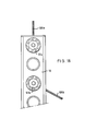
- Figs. 14 and 15 are partly diagrammatic, showing steel soldier 10, a double connector assemblies 51, 51 and a bracket 112 which replaces the fixed end unit 86.
- the bracket 112 is secured to the double connectors 51, 51 by two screw-threaded bolts 114, 114, each replacing the corresponding rod 80.
- a sloping structural member 116, to serve as a strut, is pivoted at 118 on the bracket 112.
- a tie rod 120 passes through connector assembly 51, but has a small diameter so that it does not screw-threadedly engage the connector assembly 51.
- a wing nut 122 on the rod 120 engages the soldier 10 via an end unit 124 as shown, load on the rod 120 in the direction of arrow 126 putting the rod 120 always in tension.
- a pair of soldiers 10, 10 are clamped together by a tie rod 120' which, like the rod 120 of Fig. 16, passes through the upper one of two connector assemblies 51 in the right-hand soldier, but does not screw-threadly engage the connector assembly 51, the rod 120' being of too small a diameter.
- Member 116 may be in either tension or compression, so that the vertical and horizontal load components at pivot 118 may each be respectively down and to the right, or up and to the left.
- tie rods 120a and 120b are respectively screwed into two respective connector assemblies 51 a and 51 b.
- Tie rod 120a extends in line with the soldier 10, whilst tie rod 120b extends laterally obliquely.
Landscapes
- Engineering & Computer Science (AREA)
- Architecture (AREA)
- Mechanical Engineering (AREA)
- Civil Engineering (AREA)
- Structural Engineering (AREA)
- Forms Removed On Construction Sites Or Auxiliary Members Thereof (AREA)
Priority Applications (1)
| Application Number | Priority Date | Filing Date | Title |
|---|---|---|---|
| EP90308048A EP0468108A1 (de) | 1990-07-23 | 1990-07-23 | Träger aus Stahl für Betonschalungen |
Applications Claiming Priority (1)
| Application Number | Priority Date | Filing Date | Title |
|---|---|---|---|
| EP90308048A EP0468108A1 (de) | 1990-07-23 | 1990-07-23 | Träger aus Stahl für Betonschalungen |
Publications (1)
| Publication Number | Publication Date |
|---|---|
| EP0468108A1 true EP0468108A1 (de) | 1992-01-29 |
Family
ID=8205497
Family Applications (1)
| Application Number | Title | Priority Date | Filing Date |
|---|---|---|---|
| EP90308048A Withdrawn EP0468108A1 (de) | 1990-07-23 | 1990-07-23 | Träger aus Stahl für Betonschalungen |
Country Status (1)
| Country | Link |
|---|---|
| EP (1) | EP0468108A1 (de) |
Cited By (1)
| Publication number | Priority date | Publication date | Assignee | Title |
|---|---|---|---|---|
| CN101892740A (zh) * | 2010-06-25 | 2010-11-24 | 珠海市瑞铭建筑装饰工程有限公司 | 薄壁c型钢连接结构 |
Citations (4)
| Publication number | Priority date | Publication date | Assignee | Title |
|---|---|---|---|---|
| GB1551154A (en) * | 1976-11-12 | 1979-08-22 | Beachley Machinery | Soldiers for concrete formwork |
| GB2145145A (en) * | 1983-08-19 | 1985-03-20 | Mabey Hire Co | Steel formwork soldier |
| DE3524346A1 (de) * | 1985-07-08 | 1987-01-08 | Fielitz Eberhard E Dipl Volksw | Leichtbauprofil |
| EP0227314A2 (de) * | 1985-12-24 | 1987-07-01 | Mabey Hire Company Limited | Stahlstutz |
-
1990
- 1990-07-23 EP EP90308048A patent/EP0468108A1/de not_active Withdrawn
Patent Citations (4)
| Publication number | Priority date | Publication date | Assignee | Title |
|---|---|---|---|---|
| GB1551154A (en) * | 1976-11-12 | 1979-08-22 | Beachley Machinery | Soldiers for concrete formwork |
| GB2145145A (en) * | 1983-08-19 | 1985-03-20 | Mabey Hire Co | Steel formwork soldier |
| DE3524346A1 (de) * | 1985-07-08 | 1987-01-08 | Fielitz Eberhard E Dipl Volksw | Leichtbauprofil |
| EP0227314A2 (de) * | 1985-12-24 | 1987-07-01 | Mabey Hire Company Limited | Stahlstutz |
Cited By (2)
| Publication number | Priority date | Publication date | Assignee | Title |
|---|---|---|---|---|
| CN101892740A (zh) * | 2010-06-25 | 2010-11-24 | 珠海市瑞铭建筑装饰工程有限公司 | 薄壁c型钢连接结构 |
| CN101892740B (zh) * | 2010-06-25 | 2012-02-01 | 珠海市瑞铭建筑装饰工程有限公司 | 薄壁c型钢连接结构 |
Similar Documents
| Publication | Publication Date | Title |
|---|---|---|
| US4449843A (en) | Octa hub | |
| US7631384B2 (en) | Device for damping vibrations of a guy-cable array for an engineering construction and corresponding damping method | |
| US4912794A (en) | Bridge having chords connected to each other by means of pleated steel sheets | |
| EP3356614B1 (de) | Faserverstärkte polymerstrukturen | |
| US4085556A (en) | Device for anchoring fixing means in a concrete element | |
| EP0468108A1 (de) | Träger aus Stahl für Betonschalungen | |
| CN111576240A (zh) | 一种装配式盖梁施工安全防护一体化平台 | |
| US4615063A (en) | Box girder and suspension assembly | |
| EP3019675B1 (de) | Tragwerk | |
| GB2148100A (en) | Stayed framework arrangement, for example for a shelf system | |
| US9657477B2 (en) | Structural support beam | |
| US3340664A (en) | Concrete structure with butt spliced compression and tension reinforcement | |
| KR101858534B1 (ko) | 철판 스트립 아치 교량 | |
| CN108442521B (zh) | 插板式工字钢可调长度连接节点及其施工方法 | |
| CN210737389U (zh) | 一种具有预拉应力的导梁装置及导梁组件 | |
| CA1290955C (en) | Steel soldier | |
| KR102533067B1 (ko) | 캔틸레버 길이 조정 보도교 | |
| US20060263170A1 (en) | Safety line anchor | |
| EP0188563A1 (de) | Träger | |
| KR102670849B1 (ko) | 모멘트 보강용 이중 합성 거더 | |
| EP0693600A1 (de) | Schwingungsarmer Verbundträger | |
| CN113944867A (zh) | 一种便于调节安装角度的槽钢组件 | |
| CN220598718U (zh) | 一种钢构件固定结构 | |
| RU232237U1 (ru) | Фланцевое соединение с зажимами для соединения модульных секционных многофункциональных опор освещения | |
| SU1094928A1 (ru) | Стыковое соединение подвесных устройств с колонной |
Legal Events
| Date | Code | Title | Description |
|---|---|---|---|
| PUAI | Public reference made under article 153(3) epc to a published international application that has entered the european phase |
Free format text: ORIGINAL CODE: 0009012 |
|
| AK | Designated contracting states |
Kind code of ref document: A1 Designated state(s): BE DE FR GB IT LU NL |
|
| RAP1 | Party data changed (applicant data changed or rights of an application transferred) |
Owner name: MABEY HIRE LIMITED |
|
| 17P | Request for examination filed |
Effective date: 19920703 |
|
| STAA | Information on the status of an ep patent application or granted ep patent |
Free format text: STATUS: THE APPLICATION HAS BEEN WITHDRAWN |
|
| 17Q | First examination report despatched |
Effective date: 19930628 |
|
| 18W | Application withdrawn |
Withdrawal date: 19930802 |