EP0468149B1 - Plotter - Google Patents
Plotter Download PDFInfo
- Publication number
- EP0468149B1 EP0468149B1 EP91107291A EP91107291A EP0468149B1 EP 0468149 B1 EP0468149 B1 EP 0468149B1 EP 91107291 A EP91107291 A EP 91107291A EP 91107291 A EP91107291 A EP 91107291A EP 0468149 B1 EP0468149 B1 EP 0468149B1
- Authority
- EP
- European Patent Office
- Prior art keywords
- sheet
- recording surface
- plotter
- pressure regulation
- rollers
- Prior art date
- Legal status (The legal status is an assumption and is not a legal conclusion. Google has not performed a legal analysis and makes no representation as to the accuracy of the status listed.)
- Expired - Lifetime
Links
- 230000002093 peripheral effect Effects 0.000 claims description 29
- 230000033228 biological regulation Effects 0.000 claims description 23
- 238000003801 milling Methods 0.000 claims description 14
- 230000001276 controlling effect Effects 0.000 claims description 5
- 230000001105 regulatory effect Effects 0.000 claims description 5
- 230000006835 compression Effects 0.000 claims description 4
- 238000007906 compression Methods 0.000 claims description 4
- 230000007423 decrease Effects 0.000 claims description 4
- 239000013013 elastic material Substances 0.000 claims description 3
- 230000000717 retained effect Effects 0.000 claims 1
- 238000010276 construction Methods 0.000 description 4
- 230000005540 biological transmission Effects 0.000 description 2
- 230000004048 modification Effects 0.000 description 2
- 238000012986 modification Methods 0.000 description 2
- 238000003491 array Methods 0.000 description 1
- 230000000994 depressogenic effect Effects 0.000 description 1
- 230000000694 effects Effects 0.000 description 1
- -1 for example Substances 0.000 description 1
- 239000011295 pitch Substances 0.000 description 1
Images


Classifications
-
- G—PHYSICS
- G01—MEASURING; TESTING
- G01D—MEASURING NOT SPECIALLY ADAPTED FOR A SPECIFIC VARIABLE; ARRANGEMENTS FOR MEASURING TWO OR MORE VARIABLES NOT COVERED IN A SINGLE OTHER SUBCLASS; TARIFF METERING APPARATUS; MEASURING OR TESTING NOT OTHERWISE PROVIDED FOR
- G01D15/00—Component parts of recorders for measuring arrangements not specially adapted for a specific variable
- G01D15/24—Drives for recording elements and surfaces not covered by G01D5/00
-
- B—PERFORMING OPERATIONS; TRANSPORTING
- B41—PRINTING; LINING MACHINES; TYPEWRITERS; STAMPS
- B41J—TYPEWRITERS; SELECTIVE PRINTING MECHANISMS, i.e. MECHANISMS PRINTING OTHERWISE THAN FROM A FORME; CORRECTION OF TYPOGRAPHICAL ERRORS
- B41J13/00—Devices or arrangements of selective printing mechanisms, e.g. ink-jet printers or thermal printers, specially adapted for supporting or handling copy material in short lengths, e.g. sheets
- B41J13/02—Rollers
- B41J13/076—Construction of rollers; Bearings therefor
Definitions
- the present invention relates to a plotter which automatically depicts figures, characters etc. on the surface of a sheet or automatically cuts the contours of figures, characters etc. in the surface of a sheet while moving the sheet on a recording surface. More particularly, it relates to improvements in a sheet feed mechanism which moves the sheet, such as a roll of paper, on the recording surface.
- the sheet in the case where the sheet is moved in the Y direction on the recording surface in the above way, it wobbles or meanders rightwards and leftwards on the recording surface. Then, the figure, the character or the like depicted on the sheet surface or the contours of the figure, the character or the like cut in the sheet surface become(s) distorted.
- the appearance of the distortion is conspicuous espeically on the occasion that the sheet is a roll of elongated paper and that it is moved in the Y direction on the recording surface over a long distance.
- the plotter can use only the special sheet which is formed with the small holes in both the side edges thereof. Moreover, since the sheet requires a greater width and a stage of work for forming the feeding small holes in both the side edges thereof, it becomes costly to those extents.
- Document JP-A-61 217 457 discloses a paper feed system in a printer, in which wobbling is avoided by sensing the direction of wobbling and controlling the rotary speed of split right and left feed rollers accordingly.
- the present invention has been made in view of the problems of the prior art mentioned above.
- the present invention has for its object to provide a plotter in which a sheet can be moved in a Y direction, namely, in the rotating direction of a drive roller without wobbling rightwards or leftwards on a recording surface.
- a plotter in which both the side edges of a sheet are respectively held between drive rollers and corresponding pinch rollers mounted at both the sideward parts of a recording surface in opposition to each other, and the drive rollers at both the sideward parts of the recording surface are rotated synchronously to each other, whereby the sheet is moved in the rotating direction of the drive rollers on the recording surface.
- Each of the drive rollers is formed at its peripheral surface with milling or ruggedness for preventing the sheet from slipping.
- the plotter comprises pressure regulation means for regulating respective pressures acting to press the pinch rollers at both the sideward parts of the recording surface against the surface of the sheet, and sensing means for sensing the directions and degrees of the wobbles of the sheet moving in the rotating direction of the drive rollers on the recording surface. Also, it comprises control means for controlling the pressure regulation means in accordance with the direction and degree of the wobble of the sheet as sensed by the sensing means, thereby to regulate the respective pressures acting to press the pinch rollers at both the sideward parts of the recording surface against the sheet surface.
- the pressure regulation means includes a spring which urges the pinch roller against the sheet surface, and a piston-cylinder assembly which protracts or retracts the spring for adjusting the length thereof.
- the sensing means includes photosensors which are laterally arrayed on each side of the recording surface.
- control means decreases the pressure of the pressure regulation means lying on the side of the recording surface to which the sheet wobbles or/and increases the pressure of the pressure regulation means lying on the side which is opposite to the wobble of the sheet, thereby to correct the moving orbit of the sheet.
- the drive rollers at both the sideward parts of the recording surface are synchronously rotated to move the sheet in a Y direction, namely, the rotating direction of the drive rollers on the recording surface.
- the sensing means when the sheet has begun to wobble rightwards, the rightward wobble and wobbling degree of the sheet are sensed by the sensing means.
- the control means controls the pressure regulation means so as to weaken the pressure P1 for pressing the right pinch roller against the surface of the right side edge of the sheet, to intensify the pressure P2 for pressing the left pinch roller against the surface of the left side edge of the sheet, relative to the pressure P1, or to weaken the pressure P1 and simultaneously intensify the pressure P2.
- the leftward wobble and wobbling degree of the sheet are sensed by the sensing means.
- the control means controls the pressure regulation means so as to weaken the pressure P2 for pressing the left pinch roller against the surface of the left side edge of the sheet, to intensify the pressure P1 for pressing the right pinch roller against the surface of the right side edge of the sheet, relative to the pressure P2, or to weaken the pressure P2 and simultaneously intensify the pressure P1.
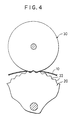
- Figs. 4 and 5 show views for elucidating the principles, and will now be referred to.
- a pinch roller 30 is intensely pressed against the surface of a sheet 10 by pressure regulation means (not shown).
- the sheet 10 held between the pinch roller 30 and a drive roller 20 the outer peripheral milling or ruggedness 22 of which is exaggeratedly illustrated, is depressed by the pinch roller 30 to fall into the state in which it bites into the tooth spaces or recesses of the peripheral milling 22 of the drive roller 20.
- the sheet 10 lying in contact with the peripheral surface of the drive roller 20 comes to have parts whose positions are lower than the tooth crests or summits of the peripheral milling 22 of the drive roller 20.
- the substantial outer diameter of the drive roller 20 decreases at the peripheral part thereof lying in contact with the sheet 10, in the amount of the depth in which the sheet 10 bites into the tooth spaces of the milling 22. Therefore, the feed speed of the sheet 10 based on a turning force transmitted from the drive roller 20 to this sheet 10, that is, the peripheral speed of the drive roller 20 at the peripheral part thereof lying in contact with the sheet 10 lowers in correspondence with the decremental diametral amount of the depth in which the sheet 10 bites into the tooth spaces of the milling 22.
- the pinch roller 30 is weakly pressed against the surface of the sheet 10 by the pressure regulation means.
- the sheet 10 held between the drive roller 20 and the pinch roller 30 falls into the state in which it overlies the tooth crests of the peripheral milling 22 of the drive roller 20.
- the position of the sheet 10 lying in contact with the peripheral surface of the drive roller 20 becomes the tooth crests of the peripheral milling 22 of the drive roller 20.
- the substantial outer diameter of the drive roller 20 increases at the peripheral part thereof lying in contact with the sheet 10, in the amount of the height of the teeth or tooth-like projections of the milling 22.
- the orbit of the sheet 10 is corrected leftwards.
- the sheet feed speed based on the turning force transmitted from the peripheral surface of the left drive roller 20 to the left side edge of the sheet 10 is made higher than the sheet feed speed based on the turning force transmitted from the peripheral surface of the right drive roller 20 to the right side edge of the sheet 10
- the orbit of the sheet 10 is corrected rightwards.
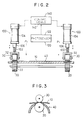
- numeral 40 designates the recording surface of the plotter called the "paper moving type", on which a sheet 10 is placed, which has a vertical section substantially in the shape of a circular arc and which is laterally long.
- a pen carriage 50 which grasps a writing utensil such as pen 60 or which grasps a cutter in a rotatable manner (in Fig. 1, the writing utensil 60 is grasped), is supported over the recording surface 40 through support means (not shown) so as to be movable in the lengthwise direction, namely, X direction of the recording surface 40.
- a driving motor, such as servomotor or stepping motor, 70 is coupled to the pen carriage 50 through transmission means (not shown) for transmitting the turning force of this motor.
- Drive rollers 20 are respectively mounted at both the sideward parts of the recording surface 40 so as to be rotatable in the Y direction of this recording surface, in the state in which the partial peripheral surfaces of the drive rollers 20 are exposed over the recording surface 40.
- a driving motor, such as servomotor or stepping motor, 80 for synchronously rotating the drive rollers 20 at both the sideward parts of the recording surface 40 in the widthwise direction, namely, Y direction of the recording surface 40 is coupled to these drive rollers 20 through transmission means (not shown) for transmitting the turning force of the motor 80.
- each of the drive rollers 20 is formed with milling or ruggedness 22 for preventing the slip of the sheet 10, for example, knurling in the shape of parallel teeth or twill teeth, or granular teeth (in the illustration, the milling in the shape of the parallel teeth is formed).
- Pinch rollers 30 are respectively mounted over and opposite the drive rollers 20 at both the sideward parts of the recording surface 40 so as to be rotatable in the Y direction of this recording surface, in the state in which the partial peripheral surfaces of the pinch rollers 30 are held in contact with those of the drive rollers 20 exposed over the recording surface 40.
- the pinch rollers 30 are formed of an elastic material, for example, rubber.
- the driving motor 80 is rotated to synchronously rotate the drive rollers 20 at both the sideward parts of the recording surface 40 and to move the sheet 10 in the Y direction on the recording surface 40.
- the driving motor 70 is rotated to move the pen carriage 50 in the X direction on the sheet 10.
- the plotter which is the preferred embodiment of the present invention comprises pressure regulation means 100 for regulating in, for example, three stages of intensities the pressure which acts to press the peripheral surface of the pinch roller 30 at the corresponding one of both the sideward parts of the recording surface 40 against the front surface of the sheet 10 sandwiched between this pinch roller 30 and the drive roller 20 associated therewith.
- a bearing 32 by which the corresponding pinch roller 30 is rotatably supported is fixed to a plotter casing (not shown) through a coiled compression spring 102 as well as an electrically-driven cylinder 104.
- the length of a piston rod 106 to project out of the electrically-driven cylinder 104 is adjusted.
- the coiled compression spring 102 fixed to the fore end of the piston rod 106 is protracted or retracted so as to adjust the length thereof in, for example, three stages of dimensions.
- the pressure, under which the peripheral surface of the pinch roller 30 rotatably supported by the fore end of the coiled compression spring 102 through the bearing 32 is pressed against the surface of the sheet 10, can be regulated in the three stages of intensities by way of example.
- the plotter comprises sensing means 120 for sensing the wobbling direction and wobbling degree of the sheet, such as a roll of paper, 10 moving in the Y direction on the recording surface 40.
- a sheet guide 42 is mounted on a part of the recording surface 40, and a plurality of (in the illustration, three) photosensors 122 are arrayed in the X direction on each side of the recording surface 40 in order to sense the wobbling direction and wobbling degree of the sheet 10 when this sheet has begun to wobble or meander either rightwards or leftwards.
- a plurality of photosensors 122 are arrayed in the X direction on each side of the recording surface 40 in order to sense the wobbling direction and wobbling degree of the sheet 10 when this sheet has begun to wobble or meander either rightwards or leftwards.
- whether or not any of the plurality of photosensors 122 disposed on each side of the recording surface 40 is covered with the sheet 10 moving on the recording surface 40 is sensed by these photosensors.
- the plotter comprises control means 140 for controlling the pressure regulation means 100 in accordance with the wobbling direction and wobbling degree of the sheet 10 sensed by the sensing means 120, thereby to regulate in, for example, the three stages of intensities the pressures which act to press the peripheral surfaces of the pinch rollers 30 at both the sideward parts of the recording surface 40 against the surface of the sheet 10 sandwiched between these pinch rollers 30 and the drive rollers 20 associated therewith.
- control means 140 includes electronic control means 142.
- the arrays of photosensors 122 disposed on the recording surface 40 sense the positions of the end edges of the sheet 10 moving on the recording surface 40. In this way, they sense the wobbling direction and wobbling degree of the sheet 10 in the case of the wobble.
- the electronic control means 142 actuates at least either of the electrically-driven cylinders 104 at both the sideward parts of the recording surface 40, whereby the projection length of at least either of the piston rods 106 to project out of the corresponding cylinder 104 is adjusted in three stages of dimensions by way of example.
- the plotter illustrated in Figs. 1 thru 3 is constructed as described above. According to this plotter, in the state in which both the side edges of the sheet 10 are respectively held between the drive rollers 20 and the corresponding pinch rollers 30 mounted at both the sideward parts of the recording surface 40 in opposition to each other, the drive rollers 20 at both the sideward parts of the recording surface 40 are synchronously rotated in the Y direction by rotating the driving motor 80, so as to move the sheet 10 in the Y direction on the recording surface 40.
- the photosensors 122 sense the wobbling direction and wobbling degree of the sheet 10.
- the control means 142 adjusts the projection lengths of the piston rods 106 projecting out of the electrically-driven cylinders 104 at both the sideward parts of the recording surface 40, in the three stages of dimensions by way of example.
- the pressure P1 or P2 pressing either of the pinch rollers 30 at both the sideward parts of the recording surface 40 against the surface of the sheet 10 is weakened, while the pressure P2 or P1 pressing the other pinch roller 30 against the surface of the sheet 10 is intensified, relative to the pressure P1 or P2.
- the moving orbit of the sheet 10 having begun to wobble either rightwards or leftwards is corrected in the Y direction.
- a sheet such as a roll of paper can be exactly moved in a sheet feed direction on a recording surface at all times without wobbling on the recording surface.
Landscapes
- Physics & Mathematics (AREA)
- General Physics & Mathematics (AREA)
Applications Claiming Priority (2)
| Application Number | Priority Date | Filing Date | Title |
|---|---|---|---|
| JP195657/90 | 1990-07-24 | ||
| JP2195657A JPH0480100A (ja) | 1990-07-24 | 1990-07-24 | プロッタ |
Publications (3)
| Publication Number | Publication Date |
|---|---|
| EP0468149A2 EP0468149A2 (en) | 1992-01-29 |
| EP0468149A3 EP0468149A3 (en) | 1992-08-19 |
| EP0468149B1 true EP0468149B1 (en) | 1995-01-18 |
Family
ID=16344824
Family Applications (1)
| Application Number | Title | Priority Date | Filing Date |
|---|---|---|---|
| EP91107291A Expired - Lifetime EP0468149B1 (en) | 1990-07-24 | 1991-05-06 | Plotter |
Country Status (4)
| Country | Link |
|---|---|
| US (1) | US5138341A (ja) |
| EP (1) | EP0468149B1 (ja) |
| JP (1) | JPH0480100A (ja) |
| DE (1) | DE69106803T2 (ja) |
Families Citing this family (42)
| Publication number | Priority date | Publication date | Assignee | Title |
|---|---|---|---|---|
| JP2946248B2 (ja) * | 1991-04-24 | 1999-09-06 | 武藤工業株式会社 | プロッタのロ−ル紙搬送装置及びロ−ル紙搬送経路調整方法 |
| US5209589A (en) * | 1991-10-25 | 1993-05-11 | Apple Computer, Inc. | Apparatus and method for minimizing printer scan error |
| WO1994002321A1 (en) * | 1992-07-24 | 1994-02-03 | Summagraphics Corporation | Sheet medium transport for printers |
| EP0622226B1 (en) * | 1993-04-30 | 1997-11-05 | Hewlett-Packard Company | Traction surface for print media feed of a heated printer |
| JP2802473B2 (ja) * | 1993-06-21 | 1998-09-24 | 麒麟麦酒 株式会社 | 包装材除去装置 |
| EP0640486B1 (en) * | 1993-08-31 | 1999-03-10 | Shinko Electric Co. Ltd. | Thermal-transfer-type color printer |
| DE4400389C1 (de) * | 1994-01-08 | 1995-05-11 | Erhardt & Leimer Gmbh | Verfahren und Vorrichtung zum Führen und Breithalten einer Warenbahn |
| JP3258203B2 (ja) * | 1994-07-26 | 2002-02-18 | 三菱電機株式会社 | シート搬送装置 |
| JP3522841B2 (ja) * | 1994-07-27 | 2004-04-26 | セントラル硝子株式会社 | 伸展加工した合成樹脂フイルムの搬送方法及びその装置 |
| US5979732A (en) * | 1994-11-04 | 1999-11-09 | Roll Systems, Inc. | Method and apparatus for pinless feeding of web to a utilization device |
| WO1996014261A1 (en) * | 1994-11-04 | 1996-05-17 | Roll Systems, Inc. | Method and apparatus for pinless feeding of web to a utilization device |
| US5967394A (en) | 1994-11-04 | 1999-10-19 | Roll Systems, Inc. | Method and apparatus for pinless feeding of web to a utilization device |
| JPH10129896A (ja) * | 1996-10-30 | 1998-05-19 | Nec Data Terminal Ltd | 連続用紙の斜行補正機構 |
| US5794829A (en) * | 1996-12-26 | 1998-08-18 | Perrault; Michael Roger | Device for lateral register adjustment of a web of material |
| DE69806983T2 (de) * | 1997-01-31 | 2002-12-12 | Alps Electric Co., Ltd. | Vorrichtung zum Zuführen von Blättern für Drucker |
| US6283655B1 (en) * | 1998-06-30 | 2001-09-04 | Gerber Scientific Products, Inc. | Friction-feed plotter with laterally-movable drive roller, and related method for plotting on sheets of different widths |
| US6170728B1 (en) * | 1999-03-22 | 2001-01-09 | Gerber Scientific Products, Inc. | Drive wheels for an apparatus performing a work operation on strip material |
| US6206263B1 (en) | 1999-05-13 | 2001-03-27 | Gerber Scientific Products, Inc. | Material advance tracking system |
| US20020053184A1 (en) * | 2000-11-03 | 2002-05-09 | Klockner Bartelt, Inc. | Automatic web height control in a packaging machine |
| US6788324B2 (en) * | 2002-02-06 | 2004-09-07 | Brady Worldwide, Inc. | Encoder-based control of printhead firing in a label printer |
| US6664995B2 (en) | 2002-02-06 | 2003-12-16 | Brady Worldwide, Inc. | Label media-specific plotter cutter depth control |
| US6616360B2 (en) | 2002-02-06 | 2003-09-09 | Brady Worldwide, Inc. | Label printer end and plotter cutting assembly |
| US6768502B2 (en) | 2002-02-06 | 2004-07-27 | Brady Worldwide, Inc. | Label printer dot line registration assembly |
| US6742858B2 (en) * | 2002-02-06 | 2004-06-01 | Brady Worldwide, Inc. | Label printer-cutter with mutually exclusive printing and cutting operations |
| US6860658B2 (en) | 2002-02-15 | 2005-03-01 | Brady Worldwide, Inc. | Ribbon wiper |
| US20070034061A1 (en) * | 2005-07-14 | 2007-02-15 | Robert Workman | Electronic paper cutting apparatus and method for cutting |
| US7845259B2 (en) | 2005-07-14 | 2010-12-07 | Provo Craft And Novelty, Inc. | Electronic paper cutting apparatus |
| US7930958B2 (en) | 2005-07-14 | 2011-04-26 | Provo Craft And Novelty, Inc. | Blade housing for electronic cutting apparatus |
| US20070012148A1 (en) * | 2005-07-14 | 2007-01-18 | Robert Workman | Electronic cutting apparatus and methods for cutting |
| JP2007084197A (ja) * | 2005-09-20 | 2007-04-05 | Fuji Xerox Co Ltd | ウェブ搬送機構、及び画像形成装置 |
| US20110280999A1 (en) | 2009-12-23 | 2011-11-17 | Provo Craft And Novelty, Inc. | Foodstuff Crafting Apparatus, Components, Assembly, and Method for Utilizing the Same |
| CN102616004B (zh) * | 2012-03-13 | 2014-10-08 | 新会江裕信息产业有限公司 | 一种搓纸轮机构 |
| CN102910477B (zh) * | 2012-11-14 | 2015-10-21 | 东莞市雅康精密机械有限公司 | 料带的展平机构 |
| CN102963748A (zh) * | 2012-12-06 | 2013-03-13 | 天津长飞鑫茂光缆有限公司 | 一种钢铝带输送装置 |
| CN103407821B (zh) * | 2013-08-21 | 2016-05-18 | 上海埃蒙特自动化系统有限公司 | 包装纸送纸机构 |
| CN104192389A (zh) * | 2014-09-04 | 2014-12-10 | 无锡市张泾宇钢机械厂 | 贴标机的推标装置 |
| CN104210719A (zh) * | 2014-09-04 | 2014-12-17 | 无锡市张泾宇钢机械厂 | 不干胶贴标机的标签分离装置 |
| CN105692300B (zh) * | 2016-04-06 | 2017-09-29 | 林彬 | 一种滚筒压紧式制鞋用皮革缠绕装置 |
| CN106938797A (zh) * | 2017-04-20 | 2017-07-11 | 合肥星源新能源材料有限公司 | 一种隔膜涂覆减小张力的装置 |
| CN108819502A (zh) * | 2018-06-01 | 2018-11-16 | 广州来丽智能科技有限公司 | 张力控制机构及具有其的数码喷印设备 |
| CN111891810A (zh) * | 2020-08-25 | 2020-11-06 | 合肥乐凯科技产业有限公司 | 一种薄膜涂布产品的膜边张力补偿装置 |
| CN118123908A (zh) * | 2024-03-07 | 2024-06-04 | 河南理工大学 | 一种利用超声波技术的裁纸装置 |
Family Cites Families (4)
| Publication number | Priority date | Publication date | Assignee | Title |
|---|---|---|---|---|
| US4029193A (en) * | 1975-03-31 | 1977-06-14 | Bunker Ramo Corporation | Printer having a platen with resilient segments |
| JPS59215880A (ja) * | 1983-05-25 | 1984-12-05 | Canon Inc | 記録装置 |
| JPH0611634B2 (ja) * | 1984-07-06 | 1994-02-16 | 日立電子株式会社 | 記録装置の紙送り機構 |
| JPS61175521A (ja) * | 1985-01-30 | 1986-08-07 | Graphtec Corp | ロ−ラ記録装置 |
-
1990
- 1990-07-24 JP JP2195657A patent/JPH0480100A/ja active Pending
-
1991
- 1991-05-03 US US07/695,604 patent/US5138341A/en not_active Expired - Fee Related
- 1991-05-06 DE DE69106803T patent/DE69106803T2/de not_active Expired - Fee Related
- 1991-05-06 EP EP91107291A patent/EP0468149B1/en not_active Expired - Lifetime
Non-Patent Citations (4)
| Title |
|---|
| PATENT ABSTRACTS OF JAPAN, Vol 10, No 388 (M-549)(2445); JP-A-61 178357 * |
| PATENT ABSTRACTS OF JAPAN, Vol 11, No 54 (M-563)(2501); JP-A-61 217457 * |
| PATENT ABSTRACTS OF JAPAN, Vol 8, No 227 (M-332)(1664); JP-A-59 108657 * |
| PATENT ABSTRACTS OF JAPAN, Vol 9, No 14 (M-352)(1737); JP-A-59 164170 * |
Also Published As
| Publication number | Publication date |
|---|---|
| DE69106803T2 (de) | 1995-05-18 |
| US5138341A (en) | 1992-08-11 |
| JPH0480100A (ja) | 1992-03-13 |
| EP0468149A3 (en) | 1992-08-19 |
| DE69106803D1 (de) | 1995-03-02 |
| EP0468149A2 (en) | 1992-01-29 |
Similar Documents
| Publication | Publication Date | Title |
|---|---|---|
| EP0468149A2 (en) | Plotter | |
| US6311539B1 (en) | Method for calibrating an edge detection system in a friction drive apparatus | |
| DE69902418T2 (de) | Reibungsantriebsgerät für Streifenmaterial | |
| DE69214223T2 (de) | Bogenzuführvorrichtung | |
| US7108257B2 (en) | Sheet-supply device | |
| CA1316756C (en) | Thermal head supporting means for a thermal printing system | |
| US4502804A (en) | Paper feeding and guiding system | |
| GB2125339A (en) | Paper feeding device for use with a printer | |
| US6098863A (en) | Web having alignment indicia and an associated web feeding and working apparatus | |
| US6170727B1 (en) | Web having alignment indicia and an associated web feeding and working apparatus | |
| EP0524535B1 (en) | Apparatus for changeably setting width of sheet guide path | |
| US20060260377A1 (en) | Automated bending machine | |
| EP0915050B1 (en) | A web having alignment indicia and an associated web feeding and working apparatus | |
| US4720714A (en) | Plotter comprising a rotatable platen displaced from a sheet feeder | |
| JP2905143B2 (ja) | シート状材料の送給及び位置決め機構を備えた印刷装置 | |
| JPH0535311U (ja) | 印字ヘツドギヤツプ自動調整装置 | |
| EP0056955B1 (en) | Paper feeding method in a printer | |
| EP1205416A2 (en) | A web having alignment indicia and an associated web feeding and working apparatus | |
| US5080514A (en) | Pin-feed apparatus for recording systems | |
| JP4067693B2 (ja) | 印字装置 | |
| JPS597031Y2 (ja) | カツタ−装置 | |
| JP2813043B2 (ja) | プリンタの印字ヘッドギャップ自動調整装置 | |
| JPH0229068Y2 (ja) | ||
| JPS6132776Y2 (ja) | ||
| JP3278029B2 (ja) | 印字装置 |
Legal Events
| Date | Code | Title | Description |
|---|---|---|---|
| PUAI | Public reference made under article 153(3) epc to a published international application that has entered the european phase |
Free format text: ORIGINAL CODE: 0009012 |
|
| AK | Designated contracting states |
Kind code of ref document: A2 Designated state(s): CH DE FR GB LI SE |
|
| PUAL | Search report despatched |
Free format text: ORIGINAL CODE: 0009013 |
|
| AK | Designated contracting states |
Kind code of ref document: A3 Designated state(s): CH DE FR GB LI SE |
|
| 17P | Request for examination filed |
Effective date: 19930204 |
|
| 17Q | First examination report despatched |
Effective date: 19940623 |
|
| GRAA | (expected) grant |
Free format text: ORIGINAL CODE: 0009210 |
|
| AK | Designated contracting states |
Kind code of ref document: B1 Designated state(s): CH DE FR GB LI SE |
|
| PG25 | Lapsed in a contracting state [announced via postgrant information from national office to epo] |
Ref country code: LI Effective date: 19950118 Ref country code: FR Effective date: 19950118 Ref country code: CH Effective date: 19950118 |
|
| REF | Corresponds to: |
Ref document number: 69106803 Country of ref document: DE Date of ref document: 19950302 |
|
| PG25 | Lapsed in a contracting state [announced via postgrant information from national office to epo] |
Ref country code: SE Effective date: 19950418 |
|
| REG | Reference to a national code |
Ref country code: CH Ref legal event code: PL |
|
| PG25 | Lapsed in a contracting state [announced via postgrant information from national office to epo] |
Ref country code: GB Effective date: 19950506 |
|
| EN | Fr: translation not filed | ||
| PLBE | No opposition filed within time limit |
Free format text: ORIGINAL CODE: 0009261 |
|
| STAA | Information on the status of an ep patent application or granted ep patent |
Free format text: STATUS: NO OPPOSITION FILED WITHIN TIME LIMIT |
|
| GBPC | Gb: european patent ceased through non-payment of renewal fee |
Effective date: 19950506 |
|
| 26N | No opposition filed | ||
| PGFP | Annual fee paid to national office [announced via postgrant information from national office to epo] |
Ref country code: DE Payment date: 19960528 Year of fee payment: 6 |
|
| PG25 | Lapsed in a contracting state [announced via postgrant information from national office to epo] |
Ref country code: DE Free format text: LAPSE BECAUSE OF NON-PAYMENT OF DUE FEES Effective date: 19980203 |