EP0468202B1 - Poussoir à galet avec compensateur de jeu hydraulique - Google Patents
Poussoir à galet avec compensateur de jeu hydraulique Download PDFInfo
- Publication number
- EP0468202B1 EP0468202B1 EP91110211A EP91110211A EP0468202B1 EP 0468202 B1 EP0468202 B1 EP 0468202B1 EP 91110211 A EP91110211 A EP 91110211A EP 91110211 A EP91110211 A EP 91110211A EP 0468202 B1 EP0468202 B1 EP 0468202B1
- Authority
- EP
- European Patent Office
- Prior art keywords
- roller
- tappet
- hydraulic
- roller tappet
- valves
- Prior art date
- Legal status (The legal status is an assumption and is not a legal conclusion. Google has not performed a legal analysis and makes no representation as to the accuracy of the status listed.)
- Expired - Lifetime
Links
- 238000002485 combustion reaction Methods 0.000 claims description 7
- 238000005096 rolling process Methods 0.000 claims description 3
- 238000010276 construction Methods 0.000 description 2
- XAGFODPZIPBFFR-UHFFFAOYSA-N aluminium Chemical compound [Al] XAGFODPZIPBFFR-UHFFFAOYSA-N 0.000 description 1
- 229910052782 aluminium Inorganic materials 0.000 description 1
- 239000011248 coating agent Substances 0.000 description 1
- 238000000576 coating method Methods 0.000 description 1
- 238000011161 development Methods 0.000 description 1
- 230000018109 developmental process Effects 0.000 description 1
- 238000007765 extrusion coating Methods 0.000 description 1
- 238000009434 installation Methods 0.000 description 1
Images


Classifications
-
- F—MECHANICAL ENGINEERING; LIGHTING; HEATING; WEAPONS; BLASTING
- F01—MACHINES OR ENGINES IN GENERAL; ENGINE PLANTS IN GENERAL; STEAM ENGINES
- F01L—CYCLICALLY OPERATING VALVES FOR MACHINES OR ENGINES
- F01L1/00—Valve-gear or valve arrangements, e.g. lift-valve gear
- F01L1/20—Adjusting or compensating clearance
- F01L1/22—Adjusting or compensating clearance automatically, e.g. mechanically
- F01L1/24—Adjusting or compensating clearance automatically, e.g. mechanically by fluid means, e.g. hydraulically
- F01L1/245—Hydraulic tappets
- F01L1/25—Hydraulic tappets between cam and valve stem
-
- F—MECHANICAL ENGINEERING; LIGHTING; HEATING; WEAPONS; BLASTING
- F01—MACHINES OR ENGINES IN GENERAL; ENGINE PLANTS IN GENERAL; STEAM ENGINES
- F01L—CYCLICALLY OPERATING VALVES FOR MACHINES OR ENGINES
- F01L1/00—Valve-gear or valve arrangements, e.g. lift-valve gear
- F01L1/12—Transmitting gear between valve drive and valve
- F01L1/14—Tappets; Push rods
- F01L1/143—Tappets; Push rods for use with overhead camshafts
-
- F—MECHANICAL ENGINEERING; LIGHTING; HEATING; WEAPONS; BLASTING
- F01—MACHINES OR ENGINES IN GENERAL; ENGINE PLANTS IN GENERAL; STEAM ENGINES
- F01L—CYCLICALLY OPERATING VALVES FOR MACHINES OR ENGINES
- F01L1/00—Valve-gear or valve arrangements, e.g. lift-valve gear
- F01L1/26—Valve-gear or valve arrangements, e.g. lift-valve gear characterised by the provision of two or more valves operated simultaneously by same transmitting-gear; peculiar to machines or engines with more than two lift-valves per cylinder
-
- F—MECHANICAL ENGINEERING; LIGHTING; HEATING; WEAPONS; BLASTING
- F01—MACHINES OR ENGINES IN GENERAL; ENGINE PLANTS IN GENERAL; STEAM ENGINES
- F01L—CYCLICALLY OPERATING VALVES FOR MACHINES OR ENGINES
- F01L2305/00—Valve arrangements comprising rollers
-
- F—MECHANICAL ENGINEERING; LIGHTING; HEATING; WEAPONS; BLASTING
- F01—MACHINES OR ENGINES IN GENERAL; ENGINE PLANTS IN GENERAL; STEAM ENGINES
- F01L—CYCLICALLY OPERATING VALVES FOR MACHINES OR ENGINES
- F01L2307/00—Preventing the rotation of tappets
-
- F—MECHANICAL ENGINEERING; LIGHTING; HEATING; WEAPONS; BLASTING
- F02—COMBUSTION ENGINES; HOT-GAS OR COMBUSTION-PRODUCT ENGINE PLANTS
- F02B—INTERNAL-COMBUSTION PISTON ENGINES; COMBUSTION ENGINES IN GENERAL
- F02B2275/00—Other engines, components or details, not provided for in other groups of this subclass
- F02B2275/18—DOHC [Double overhead camshaft]
-
- F—MECHANICAL ENGINEERING; LIGHTING; HEATING; WEAPONS; BLASTING
- F02—COMBUSTION ENGINES; HOT-GAS OR COMBUSTION-PRODUCT ENGINE PLANTS
- F02F—CYLINDERS, PISTONS OR CASINGS, FOR COMBUSTION ENGINES; ARRANGEMENTS OF SEALINGS IN COMBUSTION ENGINES
- F02F1/00—Cylinders; Cylinder heads
- F02F1/24—Cylinder heads
- F02F1/42—Shape or arrangement of intake or exhaust channels in cylinder heads
- F02F1/4214—Shape or arrangement of intake or exhaust channels in cylinder heads specially adapted for four or more valves per cylinder
-
- F—MECHANICAL ENGINEERING; LIGHTING; HEATING; WEAPONS; BLASTING
- F02—COMBUSTION ENGINES; HOT-GAS OR COMBUSTION-PRODUCT ENGINE PLANTS
- F02F—CYLINDERS, PISTONS OR CASINGS, FOR COMBUSTION ENGINES; ARRANGEMENTS OF SEALINGS IN COMBUSTION ENGINES
- F02F1/00—Cylinders; Cylinder heads
- F02F1/24—Cylinder heads
- F02F2001/244—Arrangement of valve stems in cylinder heads
- F02F2001/247—Arrangement of valve stems in cylinder heads the valve stems being orientated in parallel with the cylinder axis
Definitions
- the invention relates to a roller tappet with a hydraulic compensation element, in particular for actuating internal combustion engine gas exchange valves, a roller rolling on a cam, in particular a camshaft.
- Valve actuating tappets with hydraulic compensating elements are widely used in modern internal combustion engines.
- roller tappets with hydraulic valve lash compensation elements have also become known. Examples of this are shown in European patent application 318 151 or DE 38 14 700 A1. The roller provided on the tappet and cooperating with the cam reduces the friction work to be performed as part of the valve actuation.
- the known roller tappets with hydraulic compensating elements have a large volume and in particular have a relatively large overall height. Therefore, the invention has set itself the task of demonstrating measures by means of which the space, but especially the height of a Roller tappet can be reduced with a hydraulic compensating element.
- roller and the compensation element on the tappet are arranged essentially side by side.
- a standard hydraulic balancing element which is also installed in the known tappets, can advantageously be used here. This generally has two pistons which can be pushed into one another and which delimit a hydraulic high-pressure chamber, which can be filled from a hydraulic storage chamber via a check valve device.
- Such a or similarly designed compensating element can be guided in a roller tappet according to the invention in a known manner.
- the tappet carries the role that cooperates with the cam. This arrangement significantly reduces the height of the roller tappet.
- the ram is guided within a housing as usual by a correspondingly designed ram outer wall.
- two rollers can be provided for the moment of force-free introduction of force, which are diametrically opposite each other near the ram outer wall.
- Such an arrangement is particularly advantageous if a single tappet is provided for actuating two gas exchange valves located next to one another. Then it is advisable to assign a separate hydraulic compensation element to each valve.
- it is also possible to provide a tappet for actuating two valves with only a single, centrally arranged roller since even then an essentially tipping moment-free introduction of force is ensured, an extremely compact construction also continuing Order results.
- a plunger for actuating a plurality of gas exchange valves lying next to one another will not have a circular cylindrical shape, in this case there is advantageously no need for an anti-rotation device otherwise required for roller plungers.
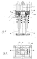
- a gas exchange valve 1 of an internal combustion engine is actuated as usual by a cam 2, which is machined out of a camshaft 3.
- a roller tappet designated in its entirety with 4 is provided for this purpose. This roller tappet is guided with its housing 5 in a guide bore 6 in the cylinder head 7, not shown, of an internal combustion engine so as to be longitudinally displaceable in the valve actuation direction.
- roller tappet 4 Essential elements of the roller tappet 4 are the rollers 9 mounted on the tappet housing 5 via rolling elements 8, as well as the hydraulic compensation element, which is also mounted in the tappet housing 5 and is designated in its entirety by 10.
- This hydraulic compensating element acts directly on the shaft of the gas exchange valve 1, while the roller 9 rolls on the cam 2.
- the hydraulic compensating element 10 is supplied with hydraulic medium via a supply bore 11 running in the housing 5 of the roller tappet 4, which is in turn connected to the oil circuit of the internal combustion engine - represented by oil channels 12 in the cylinder head 7.
- the roller tappet 4 has a centrally arranged compensating element 10 and two diametrically opposite rollers 9a, 9b arranged next to the compensating element 10. This arrangement enables an extremely compact design with a torque-free introduction of force by the cams 2 or the gas exchange valve 1, which only requires a small overall height.
- the roller tappet 4 actuates two gas exchange valves 1a, 1b.
- Each of these gas exchange valves is assigned a compensation element 10a, 10b mounted in the tappet housing.
- two rollers 9a, 9b are arranged diametrically opposite one another on the tappet outside. In the case of an internal combustion engine with several gas exchange valves connected in parallel, the construction effort can be reduced even further with this arrangement.
- the rollers can be supported by pins which are formed in one piece with the housing 5, and securing rings, plastic caps, spring elements or the like can be provided for axially securing the rollers.
- securing rings, plastic caps, spring elements or the like can be provided for axially securing the rollers.
- the plunger is guided via the sliding body-like housing 5, which can be connected to the hydraulic compensation element (s) 10, for example by plastic extrusion coating.
- the housing 5 can also be made of aluminum and can be provided with a coating at the sliding points.
- the tappet can be prevented from rotating by the geometric design of the sliding surfaces or, in the case of a cylindrical guide, by the bearing journals of the rollers or their securing elements.
- the channels 11 for supplying oil can be cast or machined into the housing 5.
- All of the exemplary embodiments are based on the same basic concept, according to which the required installation space is kept small and the resulting overall height is minimized if the hydraulic compensation element and the roller, viewed in the direction of the roller axis, are arranged essentially next to one another on a roller tappet with a hydraulic compensation element.
Landscapes
- Engineering & Computer Science (AREA)
- Mechanical Engineering (AREA)
- General Engineering & Computer Science (AREA)
- Valve-Gear Or Valve Arrangements (AREA)
Claims (5)
- Poussoir à galets avec un élément hydraulique compensateur de jeu (10, 10a, 10b) en particulier pour actionner des soupapes de passage des gaz de moteurs à combustion interne (1, 1a, 1b), dans lequel un galet (9, 9a, 9b) roule sur une came (2) en particulier une came d'un arbre à cames (3), poussoir à galet caractérisé en ce que les galets (9, 9a, 9b) et l'élément compensateur de jeu (10, 10a, 10b) sont disposés sur le poussoir (4) vu dans le sens axial du galet sensiblement côte à côte.
- Poussoir à galets selon la revendication 1, caractérisé en ce que l'on prévoit deux galets (9a, 9b) situés diamétralement l'un en face de l'autre.
- Poussoir à galets selon la revendication 1 ou 2, caractérisé en ce que l'on prévoit des éléments compensateurs de jeu (10a, 10b) séparés dans un carter commun de poussoir (5) pour les soupapes de passage des gaz (1a, 1b) situés côte à côte.
- Poussoir à galets selon la revendication 3, caractérisé en ce que le galet est disposé au milieu entre les éléments compensateurs de jeu de deux soupapes situées côte à côte.
- Poussoir à galets selon l'une des revendications 1 à 4, caractérisé en ce qu'un réservoir d'agent hydraulique (13) est disposé au centre entre les carters partiels (5a, 5b) de poussoir.
Applications Claiming Priority (2)
| Application Number | Priority Date | Filing Date | Title |
|---|---|---|---|
| DE4023886 | 1990-07-27 | ||
| DE4023886A DE4023886A1 (de) | 1990-07-27 | 1990-07-27 | Rollenstoessel mit einem hydraulischen ausgleichselement |
Publications (2)
| Publication Number | Publication Date |
|---|---|
| EP0468202A1 EP0468202A1 (fr) | 1992-01-29 |
| EP0468202B1 true EP0468202B1 (fr) | 1993-05-26 |
Family
ID=6411134
Family Applications (1)
| Application Number | Title | Priority Date | Filing Date |
|---|---|---|---|
| EP91110211A Expired - Lifetime EP0468202B1 (fr) | 1990-07-27 | 1991-06-21 | Poussoir à galet avec compensateur de jeu hydraulique |
Country Status (2)
| Country | Link |
|---|---|
| EP (1) | EP0468202B1 (fr) |
| DE (2) | DE4023886A1 (fr) |
Families Citing this family (10)
| Publication number | Priority date | Publication date | Assignee | Title |
|---|---|---|---|---|
| EP0503145B1 (fr) * | 1991-03-13 | 1994-08-24 | Bayerische Motoren Werke Aktiengesellschaft, Patentabteilung AJ-3 | Poussoir de commande d'au moins deux soupapes |
| DE4211632A1 (de) * | 1992-04-07 | 1993-10-14 | Bayerische Motoren Werke Ag | Ventilsteuerung für Gaswechselventile einer Brennkraftmaschine |
| US5361733A (en) * | 1993-01-28 | 1994-11-08 | General Motors Corporation | Compact valve lifters |
| DE4337330C2 (de) * | 1993-11-02 | 1996-03-21 | Iav Motor Gmbh | Rollenstößel mit zwei Rollen je Ventil für Ventiltriebe von Verbrennungsmotoren mit oben liegender Nockenwelle |
| DE4410123C2 (de) * | 1994-03-24 | 2003-02-20 | Ina Schaeffler Kg | Ölversorgung bei einer Ventilbetätigungseinrichtung |
| DE9406190U1 (de) * | 1994-04-14 | 1994-06-09 | INA Wälzlager Schaeffler KG, 91074 Herzogenaurach | Vorrichtung zur gleichzeitigen Betätigung von zumindest zwei Gaswechselventilen |
| DE4415270A1 (de) * | 1994-04-30 | 1995-11-02 | Opel Adam Ag | Einrichtung zur gleichzeitigen Betätigung zweier Gaswechselventile einer Brennkraftmaschine |
| DE19803246A1 (de) * | 1998-01-28 | 1999-08-05 | Meta Motoren Energietech | Vorrichtung zum Betätigen wenigstens eines Ladungswechselventils einer Brennkraftmaschine |
| DE102010027608A1 (de) | 2010-07-19 | 2012-01-19 | Schaeffler Technologies Gmbh & Co. Kg | Steuertrieb einer Brennkraftmaschine |
| WO2017028918A1 (fr) | 2015-08-19 | 2017-02-23 | Volvo Truck Corporation | Mécanisme d'actionnement de soupape variable, moteur à combustion interne et véhicule |
Family Cites Families (7)
| Publication number | Priority date | Publication date | Assignee | Title |
|---|---|---|---|---|
| US4231267A (en) * | 1978-11-01 | 1980-11-04 | General Motors Corporation | Roller hydraulic valve lifter |
| DE3622245A1 (de) * | 1986-07-02 | 1988-01-14 | Ford Werke Ag | Rollenstoesselanordnung mit verdrehsicherung, insbesondere fuer brennkraftmaschinen |
| DE3624108A1 (de) * | 1986-07-17 | 1988-01-28 | Opel Adam Ag | Ventiltrieb fuer zumindest zwei gleichzeitig zu betaetigende ventile |
| DE3638202A1 (de) * | 1986-11-08 | 1988-05-19 | Schaeffler Waelzlager Kg | Hydraulisches spielausgleichselement |
| US4807575A (en) * | 1987-11-23 | 1989-02-28 | General Motors Corporation | Hydraulic lash adjuster with multi-directional check valve |
| DE3743854A1 (de) * | 1987-12-23 | 1989-07-06 | Michael Stirm | Vierventilsteuerung mit oberen abstuetzelementen |
| DE3814700A1 (de) * | 1988-04-30 | 1989-11-09 | Schaeffler Waelzlager Kg | Hydraulisches spielausgleichselement |
-
1990
- 1990-07-27 DE DE4023886A patent/DE4023886A1/de not_active Withdrawn
-
1991
- 1991-06-21 EP EP91110211A patent/EP0468202B1/fr not_active Expired - Lifetime
- 1991-06-21 DE DE9191110211T patent/DE59100131D1/de not_active Expired - Fee Related
Also Published As
| Publication number | Publication date |
|---|---|
| DE4023886A1 (de) | 1992-01-30 |
| DE59100131D1 (de) | 1993-07-01 |
| EP0468202A1 (fr) | 1992-01-29 |
Similar Documents
| Publication | Publication Date | Title |
|---|---|---|
| DE69107687T2 (de) | Steuervorrichtung mit Nockenwelle und Kraftübertragungsmittel mit Rolle. | |
| DE4302877C2 (de) | Stößel | |
| DE19681400B4 (de) | Hydraulisches Abstützelement für eine Ventilsteuerung einer Brennkraftmaschine | |
| EP0468202B1 (fr) | Poussoir à galet avec compensateur de jeu hydraulique | |
| DE2814096A1 (de) | Mehrzylindrige brennkraftmaschine mit ventilabschaltung | |
| DE1016497B (de) | Vorrichtung zur Sicherung der Pumpenstoessel von Einspritzpumpen gegen Drehen | |
| DE2652154A1 (de) | Hydraulisches spielausgleichselement fuer verbrennungsmotoren | |
| DE3503312A1 (de) | Hydraulische spielnachstellung | |
| DE10146129A1 (de) | Schaltelement für einen Ventiltrieb einer Brennkraftmaschine | |
| DE102016114978A1 (de) | Pleuel für eine Brennkraftmaschine mit variabler Verdichtung | |
| EP0099873A2 (fr) | Soupape rotative cylindrique avec organe d'étanchéité pour des moteurs à pistons | |
| DE10146131A1 (de) | Schaltelement für einen Ventiltrieb einer Brennkraftmaschine | |
| DE69213219T4 (de) | Mehrzylindrische zweitakt brennkraftmaschine | |
| DE102015209336A1 (de) | Hydraulisches Ausgleichselement für den Ventiltrieb einer Brennkraftmaschine | |
| DE4334518A1 (de) | Hydraulische Ventilspielausgleichsvorrichtung für ein nockengesteuertes Hubventil | |
| EP0196418B1 (fr) | Poussoir hydraulique pour moteurs à combustion interne | |
| DE69306736T2 (de) | Direkt wirkender Stössel | |
| DE2649219A1 (de) | Hydraulische spielnachstelleinrichtung | |
| DE8717456U1 (de) | Rotationskolbenpumpe mit ungleichmäßiger Pumpleistung, insbesondere zur Ventilsteuerung von Verbrennungskraftmaschinen | |
| DE4117006C2 (fr) | ||
| WO1992014039A1 (fr) | Element hydraulique de compensation du jeu pour moteurs a combustion interne | |
| DE2517370A1 (de) | Hydraulische spielausgleichsvorrichtung | |
| DE102015221038A1 (de) | Abstützelement für einen Ventiltrieb einer Brennkraftmaschine | |
| DE4401011C2 (de) | Gebaute Nockenwelle | |
| DE102013209166A1 (de) | Zentralventil mit einem Steuerkolben zur Steuerung der Ölversorgung für einen Nockenwellenversteller |
Legal Events
| Date | Code | Title | Description |
|---|---|---|---|
| PUAI | Public reference made under article 153(3) epc to a published international application that has entered the european phase |
Free format text: ORIGINAL CODE: 0009012 |
|
| AK | Designated contracting states |
Kind code of ref document: A1 Designated state(s): DE FR GB IT |
|
| 17P | Request for examination filed |
Effective date: 19920207 |
|
| 17Q | First examination report despatched |
Effective date: 19920611 |
|
| GRAA | (expected) grant |
Free format text: ORIGINAL CODE: 0009210 |
|
| AK | Designated contracting states |
Kind code of ref document: B1 Designated state(s): DE FR GB IT |
|
| REF | Corresponds to: |
Ref document number: 59100131 Country of ref document: DE Date of ref document: 19930701 |
|
| GBT | Gb: translation of ep patent filed (gb section 77(6)(a)/1977) |
Effective date: 19930621 |
|
| ET | Fr: translation filed | ||
| ITF | It: translation for a ep patent filed | ||
| PLBE | No opposition filed within time limit |
Free format text: ORIGINAL CODE: 0009261 |
|
| STAA | Information on the status of an ep patent application or granted ep patent |
Free format text: STATUS: NO OPPOSITION FILED WITHIN TIME LIMIT |
|
| 26N | No opposition filed | ||
| PGFP | Annual fee paid to national office [announced via postgrant information from national office to epo] |
Ref country code: DE Payment date: 19970602 Year of fee payment: 7 |
|
| PGFP | Annual fee paid to national office [announced via postgrant information from national office to epo] |
Ref country code: GB Payment date: 19970619 Year of fee payment: 7 |
|
| PGFP | Annual fee paid to national office [announced via postgrant information from national office to epo] |
Ref country code: FR Payment date: 19970630 Year of fee payment: 7 |
|
| PG25 | Lapsed in a contracting state [announced via postgrant information from national office to epo] |
Ref country code: GB Free format text: LAPSE BECAUSE OF NON-PAYMENT OF DUE FEES Effective date: 19980621 |
|
| GBPC | Gb: european patent ceased through non-payment of renewal fee |
Effective date: 19980621 |
|
| PG25 | Lapsed in a contracting state [announced via postgrant information from national office to epo] |
Ref country code: FR Free format text: LAPSE BECAUSE OF NON-PAYMENT OF DUE FEES Effective date: 19990226 |
|
| PG25 | Lapsed in a contracting state [announced via postgrant information from national office to epo] |
Ref country code: DE Free format text: LAPSE BECAUSE OF NON-PAYMENT OF DUE FEES Effective date: 19990401 |
|
| REG | Reference to a national code |
Ref country code: FR Ref legal event code: ST |
|
| PG25 | Lapsed in a contracting state [announced via postgrant information from national office to epo] |
Ref country code: IT Free format text: LAPSE BECAUSE OF NON-PAYMENT OF DUE FEES;WARNING: LAPSES OF ITALIAN PATENTS WITH EFFECTIVE DATE BEFORE 2007 MAY HAVE OCCURRED AT ANY TIME BEFORE 2007. THE CORRECT EFFECTIVE DATE MAY BE DIFFERENT FROM THE ONE RECORDED. Effective date: 20050621 |