EP0468226A1 - Dispositif de désintégration pour un mélangeur ou similaire - Google Patents
Dispositif de désintégration pour un mélangeur ou similaire Download PDFInfo
- Publication number
- EP0468226A1 EP0468226A1 EP91110747A EP91110747A EP0468226A1 EP 0468226 A1 EP0468226 A1 EP 0468226A1 EP 91110747 A EP91110747 A EP 91110747A EP 91110747 A EP91110747 A EP 91110747A EP 0468226 A1 EP0468226 A1 EP 0468226A1
- Authority
- EP
- European Patent Office
- Prior art keywords
- stator
- rotor
- disks
- spacer
- shaft
- Prior art date
- Legal status (The legal status is an assumption and is not a legal conclusion. Google has not performed a legal analysis and makes no representation as to the accuracy of the status listed.)
- Granted
Links
Images
Classifications
-
- B—PERFORMING OPERATIONS; TRANSPORTING
- B01—PHYSICAL OR CHEMICAL PROCESSES OR APPARATUS IN GENERAL
- B01F—MIXING, e.g. DISSOLVING, EMULSIFYING OR DISPERSING
- B01F27/00—Mixers with rotary stirring devices in fixed receptacles; Kneaders
- B01F27/80—Mixers with rotary stirring devices in fixed receptacles; Kneaders with stirrers rotating about a substantially vertical axis
- B01F27/90—Mixers with rotary stirring devices in fixed receptacles; Kneaders with stirrers rotating about a substantially vertical axis with paddles or arms
- B01F27/902—Mixers with rotary stirring devices in fixed receptacles; Kneaders with stirrers rotating about a substantially vertical axis with paddles or arms cooperating with intermeshing elements fixed on the receptacle walls
Definitions
- the invention relates to a disintegrating device for mixers or comparable machines, which has a stator fastened in the container of the mixer and a rotor which can be moved relative to the stator, with a rotatably mounted shaft of the rotor which projects through the wall of the container and is connected or connectable to a drive Unlocking tools are provided which interact with other tools attached to the stator during operation.
- a previously known device of this type has a disk on the rotor, on which pins are provided which interact with parts of the stator surrounding the rotor when the disk rotates.
- the invention has for its object to provide an improved digester for use in mixers, which is simple and inexpensive to manufacture and is extremely effective in its operation, so that mixed goods of all types can be digested well and evenly within the shortest operating times.
- the unlocking device has both radially running - for example knife-shaped - tools on the stator as well as on the rotor, which work together like scissors but without contact, so that hard, fibrous and difficult to handle materials can be digested well and intensively. Even when processing short, fibrous mixes, the risk of nests forming is avoided.
- the interacting parts of the stator and of the rotor are simple and inexpensive to produce, since they are each preferably plate-shaped or disk-shaped and thus have no complicated shapes.
- the individual plates or disks of the device can be assembled one above the other without any problems, so that a multi-stage or multi-layer disintegration device can be manufactured with simple means and thus inexpensively according to the modular principle.
- the knife-like tools of the stator and rotor can, in particular if hard mixes are to be processed, be additionally armored without difficulty.
- the shear gaps between the tools of the rotor and stator can be adapted to the products to be unlocked in the unlocking device according to the invention, simply by inserting spacer elements or spacers of different thickness between the individual layers of the stator and rotor, which are located outside the areas of the interacting unlockers - or shaving tools.
- the knives or knife-shaped tools of the stator can also be designed with rounded edges and also as a tapered conical body. Conical knives or tools are particularly advantageous for breaking up fiber material, because such tools avoid nests or so-called rice grain formation.
- the digestion device according to the invention is, so to speak, a dispersant having shear segments.
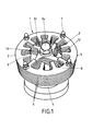
- the unlocking device 1 shown in the drawing has a stator 2 and a rotor 3 arranged therein and rotatable relative thereto.
- the stator 2 is arranged on a foot 4 which is to be fastened to the inside of the wall of a mixing container (not shown in more detail).
- the stator 2 consists of a number of plate-shaped disks 5 arranged one above the other, in the exemplary embodiment shown consisting of a total of four disks, between which spacer rings 6 are arranged in each case.
- This package of disks 5 and spacer rings 6 is held together by bolts inserted through them in the edge area, and head nuts 7 are screwed onto their outer ends.
- the bolts themselves cannot be seen in the drawing, since they are covered by the disks 5, the spacer rings 6 and the head nuts 7.
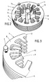
- the individual disks 5 have an outer annular body 8, from which radially inward a number of tongues 9, which are roughly rectangular in plan, extend to the center of the disks in question, but end at a distance from this center, so that in the middle Area of each disc 5 is a free space 10.
- a shaft 11 arranged coaxially to the stator, which forms part of the rotor 3 and passes through the wall of the mixing container (not shown).
- the shaft On the outside of the mixing container, the shaft is rotatably supported in a manner which is not shown here but is known per se and is connected to a drive which is also not shown.
- star-shaped - shredders 12 are arranged in a rotationally fixed manner, which project with radial arms 13 which are approximately tangential to the shaft between the tongues 9 of two disks 5 arranged directly one above the other, so that the shredders 12 at the height of the spacer rings 6 Stator are arranged. Since in the illustrated embodiment the stator 2 has four disks 5 and thus three spacer rings 6, three shredders 12 are also attached to the shaft 11 of the rotor 3. These shredders 12 are kept at the necessary axial distance from one another by means of spacers, not shown. A head nut 14 screwed onto the outer end of the shaft 11 holds the parts of the rotor 3 together. The number of disks 5 and shredder 12 is variable, however, because the unlocking device 1 can be assembled and removed on the modular principle.
- both the stator 2 and the rotor 3 are largely constructed from plate-shaped or flat parts which can be punched out of metal plates.
- the arms 13 of the star-shaped shredders 12 of the rotor 3 interact with the radially inwardly projecting tongues 9 of the disks 5 of the stator 2 when the rotor 3 is driven.
- the rotor 3 can be driven at high speed, the material or mixed material reaching the unlocking device 1 is thrown into the area of the tongues 9 and arms 13 interacting as unlocking tools and then quickly, intensively and uniformly unlocked by the tools of the unlocking device 1.
- the inwardly projecting tongues 9 of the disks 5 of the stator 2 arranged one above the other and the approximately radially outwardly extending arms 13 of the star-shaped shredder 12 of the rotor 3 are arranged vertically one above the other, the tongues 9 of the stator 2 and / or the arms 13 of the rotor 3 can also be arranged offset in relation to one another in the different planes of the unlocking device 1 if this should be advantageous for certain unlocking problems.
- the washers 5 of the stator 2 are cut or stamped out of sheet steel, so that the annular body 8 and the inwardly directed tongues 9 arranged thereon are formed in one piece and lie in one plane.
- the star-shaped shredders 12 of the rotor 3 are cut out or stamped out of sheet steel, so that their arms 13, which run radially or in this case approximately tangentially to the shaft 11, are arranged in one plane.
- Both the disks 5 and the star-shaped shredder 12 can be made of the same material, namely sheet steel, and can also have the same thickness.
- spacer rings 6 of the stator 2 and the spacers of the rotor 3, which are not recognizable in the drawing, can likewise be made of sheet steel, but also of other material.
- spacer rings and spacer disks of different thicknesses can be installed, but their thickness is in any case at least somewhat greater than the thickness of the disks 5 and the star-shaped shredder 12, so that the rotor 3 is set up in relation to the stator 2 can be that his arms 13 do not come into contact with the tongues 9 or touch the tongues during circulation.
- the tongues 9 and arms 13 forming the tools of the unlocking device 1 interact with one another like scissors, but the interaction is contactless, so that the rotary movements of the rotor 3, which is preferably driven at high speed, cannot be inhibited by contact with the stator 2. This ensures a uniform and, in the end, gentle disintegration of the mix or other materials.
- the tongues 9 and arms 13 serving as unlocking or shearing tools are sharp-edged or angular. But they can also taper in the direction of the cut, as can the arms of the rotor be formed or taper to the outside.
- uninterrupted spacer rings 6 are shown as spacer elements between the disks 5 of the stator 2. This results in closed shear planes inside the stator.
- individual ring segments or individual spacer bushes can also be installed as spacer elements, as a result of which partially open or completely open shear planes are obtained in the stator.
- spacer elements or spacers such as spacer rings, spacer ring segments or spacer bushes can be separate components, such as the spacer rings 6, but it is also possible to connect these spacer elements to the disks 5 of the stator 2, which are intended to keep them apart, in one piece.
- the individual disks 5 of the stator 2 can be manufactured in one piece with the relevant spacer elements, it being possible to provide each disk on one side with corresponding spacer elements or to equip every second disk on both sides with spacer elements, while the others Disks flat punched bodies can be like the disks 5 shown in the drawing.
- the spacer rings 6 or corresponding ring segments can be smooth, rough, corrugated or toothed on the inside.
- the annular or partially annular spacer elements contribute at least to a limited extent to the unlocking process.
- the shear elements of the disks 5 of the stator 2 can, as shown in the drawing, be designed as tongues 9 with smooth ends, but the inwardly facing ends of the tongue-shaped shear elements can also be rounded off, just as the shear elements can taper inwards.
- the arms 13 of the rotor 3 can in the same way be smooth, rounded or tapered at the outward end.
- the arms of the rotor can also be knife-like or rod-shaped.
- the thickness of the tongues 9 of the stator 2 can decrease towards the outer end, so that the shear gap has a uniform width over its radial length only when the thickness of the interacting tongues 9 and arms is reduced 13 is uniform.
- the thickness of the tongues 9 of the stator 2 and possibly also the thickness of the arms 13 of the rotor 3 can vary in the horizontal direction or within one plane, so that these shear elements have an approximately wedge-shaped cross section. This results in a narrowing of the shear gap in the tangential direction, it being expedient that the thinner section of the wedge-shaped cross-section of these shear elements points forward in the working direction, so that the shear gap narrows in the working direction and thus has an even better effect on the material to be broken down.
- these shear elements can also be attached to the annular body 8, in particular if they are rod-shaped elements, by screwing, by plug connection or in a similar manner the discs 5 of the stator 2 are attached. Then these shear elements can be exchanged, for example if they are worn out, just as they can be made of a different material than the disks 5 holding them.
- Additional knives or wing-like rotor elements can be attached to the rotor 3 below the first and above the last level of the stator 2. This results in a stronger axial conveyance of the material to be unlocked in the area of the unlocking device 1, as well as possible congestion of the material being quickly and uniformly resolved.
Landscapes
- Chemical & Material Sciences (AREA)
- Chemical Kinetics & Catalysis (AREA)
- Crushing And Pulverization Processes (AREA)
- Mixers Of The Rotary Stirring Type (AREA)
- Processing And Handling Of Plastics And Other Materials For Molding In General (AREA)
Applications Claiming Priority (2)
| Application Number | Priority Date | Filing Date | Title |
|---|---|---|---|
| DE4023301 | 1990-07-21 | ||
| DE4023301A DE4023301A1 (de) | 1990-07-21 | 1990-07-21 | Aufschliessvorrichtung fuer mischer o. dgl. |
Publications (2)
| Publication Number | Publication Date |
|---|---|
| EP0468226A1 true EP0468226A1 (fr) | 1992-01-29 |
| EP0468226B1 EP0468226B1 (fr) | 1994-08-31 |
Family
ID=6410802
Family Applications (1)
| Application Number | Title | Priority Date | Filing Date |
|---|---|---|---|
| EP91110747A Expired - Lifetime EP0468226B1 (fr) | 1990-07-21 | 1991-06-28 | Dispositif de désintégration pour un mélangeur ou similaire |
Country Status (3)
| Country | Link |
|---|---|
| EP (1) | EP0468226B1 (fr) |
| DE (2) | DE4023301A1 (fr) |
| ES (1) | ES2061122T3 (fr) |
Cited By (2)
| Publication number | Priority date | Publication date | Assignee | Title |
|---|---|---|---|---|
| WO2016019213A1 (fr) * | 2014-07-31 | 2016-02-04 | Dow Global Technologies Llc | Appareil de mélange dynamique en ligne pour la floculation et la déshydratation de résidus fins de sables bitumineux |
| IT201800001011A1 (it) * | 2018-01-16 | 2019-07-16 | Claudio Viero | Sistema per emulsionare e impastare tramite insufflazione di aria e/o gas utilizzando un mixer emulsionatore supportato ad entrambe le estremità, programmabile per lavorazioni a ciclo continuo e alternato e i cui rotore e statore sono costituiti da parti modulari impilabili |
Families Citing this family (1)
| Publication number | Priority date | Publication date | Assignee | Title |
|---|---|---|---|---|
| DE4313149C2 (de) * | 1993-04-22 | 1997-11-06 | Lipp Mischtechnik Gmbh | Vorrichtung zum Mahlen und Intensivmischen von Schüttgütern und/oder Flüssigkeiten |
Citations (9)
| Publication number | Priority date | Publication date | Assignee | Title |
|---|---|---|---|---|
| US1475638A (en) * | 1923-01-13 | 1923-11-27 | Low Engineering Company Ltd | Mixing apparatus |
| US2033413A (en) * | 1932-04-23 | 1936-03-10 | Kraft Phenix Cheese Corp | Emulsifying method |
| US2581918A (en) * | 1950-02-03 | 1952-01-08 | Firestone Tire & Rubber Co | Foaming apparatus |
| FR1134428A (fr) * | 1953-06-25 | 1957-04-11 | Dunlop Rubber Co | Appareil mélangeur perfectionné |
| US2851256A (en) * | 1955-01-13 | 1958-09-09 | American Mach & Foundry | Closed continuous mixer |
| GB841743A (en) * | 1958-03-21 | 1960-07-20 | Ici Ltd | Improvements in or relating to mixing apparatus |
| GB2048701A (en) * | 1979-05-03 | 1980-12-17 | Rubber & Plastic Res Ass | Mixing device |
| EP0135219A1 (fr) * | 1983-07-27 | 1985-03-27 | Stork Brabant B.V. | Dispositif pour produire de la mousse |
| DE3543293A1 (de) * | 1985-12-07 | 1987-06-11 | Krampe & Co | Mischkopf fuer einen kontinuierlich arbeitenden schaummischer |
-
1990
- 1990-07-21 DE DE4023301A patent/DE4023301A1/de not_active Withdrawn
-
1991
- 1991-06-28 ES ES91110747T patent/ES2061122T3/es not_active Expired - Lifetime
- 1991-06-28 DE DE59102721T patent/DE59102721D1/de not_active Expired - Fee Related
- 1991-06-28 EP EP91110747A patent/EP0468226B1/fr not_active Expired - Lifetime
Patent Citations (9)
| Publication number | Priority date | Publication date | Assignee | Title |
|---|---|---|---|---|
| US1475638A (en) * | 1923-01-13 | 1923-11-27 | Low Engineering Company Ltd | Mixing apparatus |
| US2033413A (en) * | 1932-04-23 | 1936-03-10 | Kraft Phenix Cheese Corp | Emulsifying method |
| US2581918A (en) * | 1950-02-03 | 1952-01-08 | Firestone Tire & Rubber Co | Foaming apparatus |
| FR1134428A (fr) * | 1953-06-25 | 1957-04-11 | Dunlop Rubber Co | Appareil mélangeur perfectionné |
| US2851256A (en) * | 1955-01-13 | 1958-09-09 | American Mach & Foundry | Closed continuous mixer |
| GB841743A (en) * | 1958-03-21 | 1960-07-20 | Ici Ltd | Improvements in or relating to mixing apparatus |
| GB2048701A (en) * | 1979-05-03 | 1980-12-17 | Rubber & Plastic Res Ass | Mixing device |
| EP0135219A1 (fr) * | 1983-07-27 | 1985-03-27 | Stork Brabant B.V. | Dispositif pour produire de la mousse |
| DE3543293A1 (de) * | 1985-12-07 | 1987-06-11 | Krampe & Co | Mischkopf fuer einen kontinuierlich arbeitenden schaummischer |
Cited By (2)
| Publication number | Priority date | Publication date | Assignee | Title |
|---|---|---|---|---|
| WO2016019213A1 (fr) * | 2014-07-31 | 2016-02-04 | Dow Global Technologies Llc | Appareil de mélange dynamique en ligne pour la floculation et la déshydratation de résidus fins de sables bitumineux |
| IT201800001011A1 (it) * | 2018-01-16 | 2019-07-16 | Claudio Viero | Sistema per emulsionare e impastare tramite insufflazione di aria e/o gas utilizzando un mixer emulsionatore supportato ad entrambe le estremità, programmabile per lavorazioni a ciclo continuo e alternato e i cui rotore e statore sono costituiti da parti modulari impilabili |
Also Published As
| Publication number | Publication date |
|---|---|
| DE59102721D1 (de) | 1994-10-06 |
| EP0468226B1 (fr) | 1994-08-31 |
| ES2061122T3 (es) | 1994-12-01 |
| DE4023301A1 (de) | 1992-01-23 |
Similar Documents
| Publication | Publication Date | Title |
|---|---|---|
| DE19523704C2 (de) | Vorrichtung zur mechanischen Behandlung von hochkonsistentem Faserstoff | |
| DE68905063T2 (de) | Zerkleinerer. | |
| DE3782387T2 (de) | Muellzerkleinerungsmaschine und seitenschienen dafuer. | |
| CH616604A5 (fr) | ||
| DD284610A5 (de) | Scheibenkneter | |
| DE60315052T2 (de) | Knetverfahren und Knetmaschine für Teigmittel, insbesondere für Backwaren | |
| EP0304604B1 (fr) | Mélangeur avec agitateur et broyeur | |
| DE2823245C2 (de) | Schneidsatz für eine Vorrichtung zum Zerkleinern von Nahrungsmitteln | |
| EP0422272B1 (fr) | Dispositif de malaxage et pétrissage | |
| EP2514531B1 (fr) | Rondelle de forme pour le traitement d'aliments | |
| DE2755898A1 (de) | Zerkleinerungsvorrichtung, beispielswiese brechwerk | |
| EP0500705B1 (fr) | Dispositif de broyage | |
| EP0468226B1 (fr) | Dispositif de désintégration pour un mélangeur ou similaire | |
| DE2640334C2 (de) | Feldhäcksler | |
| DE4301787C1 (de) | Messer für Fleischwölfe | |
| DE8718067U1 (de) | Vorrichtung zum Zerkleinern von Abfall | |
| EP0667190B1 (fr) | Panneau de tamisage et procédé de fabrication du panneau de tamisage | |
| DE7818838U1 (de) | Maschine zum zerkleinern von abfallstoffen | |
| DE19606746C1 (de) | Trichterhacker zum Zerkleinern von insbesondere Holz | |
| EP2549892B1 (fr) | Porte-couteaux pour dispositif de désintégration de matière organique | |
| EP0956901A1 (fr) | Arbre coupant muni d'éléments coupants pour appareil désintégrateur | |
| DE2457403C2 (de) | Vorrichtung zum Zerspanen von Material, insbesondere von Holz | |
| EP0302131B1 (fr) | Broyeur | |
| DE2827544A1 (de) | Zerkleinerungsanlage | |
| DE202020103763U1 (de) | Messer |
Legal Events
| Date | Code | Title | Description |
|---|---|---|---|
| PUAI | Public reference made under article 153(3) epc to a published international application that has entered the european phase |
Free format text: ORIGINAL CODE: 0009012 |
|
| AK | Designated contracting states |
Kind code of ref document: A1 Designated state(s): AT BE CH DE DK ES FR GB GR IT LI LU NL SE |
|
| 17P | Request for examination filed |
Effective date: 19920724 |
|
| 17Q | First examination report despatched |
Effective date: 19931119 |
|
| RBV | Designated contracting states (corrected) |
Designated state(s): AT BE CH DE DK ES FR GB IT LI NL |
|
| RBV | Designated contracting states (corrected) |
Designated state(s): CH DE ES FR GB IT LI |
|
| GRAA | (expected) grant |
Free format text: ORIGINAL CODE: 0009210 |
|
| AK | Designated contracting states |
Kind code of ref document: B1 Designated state(s): CH DE ES FR GB IT LI |
|
| GBT | Gb: translation of ep patent filed (gb section 77(6)(a)/1977) |
Effective date: 19940906 |
|
| ITF | It: translation for a ep patent filed | ||
| REF | Corresponds to: |
Ref document number: 59102721 Country of ref document: DE Date of ref document: 19941006 |
|
| ET | Fr: translation filed | ||
| REG | Reference to a national code |
Ref country code: ES Ref legal event code: FG2A Ref document number: 2061122 Country of ref document: ES Kind code of ref document: T3 |
|
| PLBI | Opposition filed |
Free format text: ORIGINAL CODE: 0009260 |
|
| 26 | Opposition filed |
Opponent name: HAENDLE GMBH & CO. KG MASCHINEN UND ANLAGENBAU Effective date: 19950530 |
|
| PLBL | Opposition procedure terminated |
Free format text: ORIGINAL CODE: EPIDOS OPPC |
|
| PLBM | Termination of opposition procedure: date of legal effect published |
Free format text: ORIGINAL CODE: 0009276 |
|
| STAA | Information on the status of an ep patent application or granted ep patent |
Free format text: STATUS: OPPOSITION PROCEDURE CLOSED |
|
| 27C | Opposition proceedings terminated |
Effective date: 19960530 |
|
| REG | Reference to a national code |
Ref country code: GB Ref legal event code: IF02 |
|
| PGFP | Annual fee paid to national office [announced via postgrant information from national office to epo] |
Ref country code: GB Payment date: 20020520 Year of fee payment: 12 |
|
| PGFP | Annual fee paid to national office [announced via postgrant information from national office to epo] |
Ref country code: FR Payment date: 20020528 Year of fee payment: 12 |
|
| PGFP | Annual fee paid to national office [announced via postgrant information from national office to epo] |
Ref country code: CH Payment date: 20020531 Year of fee payment: 12 |
|
| PGFP | Annual fee paid to national office [announced via postgrant information from national office to epo] |
Ref country code: ES Payment date: 20020701 Year of fee payment: 12 |
|
| PGFP | Annual fee paid to national office [announced via postgrant information from national office to epo] |
Ref country code: DE Payment date: 20020826 Year of fee payment: 12 |
|
| PG25 | Lapsed in a contracting state [announced via postgrant information from national office to epo] |
Ref country code: GB Free format text: LAPSE BECAUSE OF NON-PAYMENT OF DUE FEES Effective date: 20030628 |
|
| PG25 | Lapsed in a contracting state [announced via postgrant information from national office to epo] |
Ref country code: LI Free format text: LAPSE BECAUSE OF NON-PAYMENT OF DUE FEES Effective date: 20030630 Ref country code: ES Free format text: LAPSE BECAUSE OF NON-PAYMENT OF DUE FEES Effective date: 20030630 Ref country code: CH Free format text: LAPSE BECAUSE OF NON-PAYMENT OF DUE FEES Effective date: 20030630 |
|
| PG25 | Lapsed in a contracting state [announced via postgrant information from national office to epo] |
Ref country code: DE Free format text: LAPSE BECAUSE OF NON-PAYMENT OF DUE FEES Effective date: 20040101 |
|
| REG | Reference to a national code |
Ref country code: CH Ref legal event code: PL |
|
| GBPC | Gb: european patent ceased through non-payment of renewal fee |
Effective date: 20030628 |
|
| PG25 | Lapsed in a contracting state [announced via postgrant information from national office to epo] |
Ref country code: FR Free format text: LAPSE BECAUSE OF NON-PAYMENT OF DUE FEES Effective date: 20040227 |
|
| REG | Reference to a national code |
Ref country code: FR Ref legal event code: ST |
|
| REG | Reference to a national code |
Ref country code: ES Ref legal event code: FD2A Effective date: 20030630 |
|
| PG25 | Lapsed in a contracting state [announced via postgrant information from national office to epo] |
Ref country code: IT Free format text: LAPSE BECAUSE OF NON-PAYMENT OF DUE FEES;WARNING: LAPSES OF ITALIAN PATENTS WITH EFFECTIVE DATE BEFORE 2007 MAY HAVE OCCURRED AT ANY TIME BEFORE 2007. THE CORRECT EFFECTIVE DATE MAY BE DIFFERENT FROM THE ONE RECORDED. Effective date: 20050628 |